
Subscribe to Our Youtube Channel
Related Manuals for ESAB ET 186i AC/DC


Summary of Contents for ESAB ET 186i AC/DC
- Page 1 ESAB ET 186i AC/DC Inverter Arc Welder Operating Manual Art# A-13113 3163339 Révision : AA Issue Date: June 1, 2016 Manual No.: 0-5425 esab.com...
- Page 2 WE APPRECIATE YOUR BUSINESS! Congratulations on your new ESAB product. We are proud to have you as our customer and will strive to provide you with the best service and reliability in the industry. This product is backed by our extensive warranty and world-wide service network.
- Page 3 While the information contained in this Manual represents the Manufacturer's best judgement, the Manufacturer assumes no liability for its use. Welding Power Supply ESAB ET 186i AC/DC Inverter Arc Welder Operating Manual Number 0-5425 Published by: ESAB 2800 Airport Rd.
- Page 4 Be sure this information reaches the operator. You can get extra copies through your supplier. CAUTION These INSTRUCTIONS are for experienced operators. If you are not fully familiar with the principles of operation and safe practices for arc welding and cutting equip- ment, we urge you to read our booklet, “Precautions and Safe Practices for Arc Welding, Cutting, and Gouging,”...
-
Page 5: Table Of Contents
ET 186i AC/DC Power Source Controls, Indicators and Features ....3-4 3.09 ET 186i AC/DC - STICK Programming Mode ..........3-9 3.10 ET ET 186i AC/DC – LIFT TIG and HF TIG Programming Mode ....3-11 3.11 Short Circuit Protection While Welding ............3-15 3.12 Victor Regulator .................... - Page 6 Routine Service and Calibration Requirements ..........5-2 5.04 Cleaning the Welding Power Source ............... 5-4 SECTION 6: KEY SPARE PARTS ................... 6-1 6.01 Power Source ....................6-1 APPENDIX 1 : CIRCUIT DIAGRAM ................ A-1 APPENDIX 2 : ET 186i AC/DC SETUP GUIDE ............A-2...
-
Page 7: Section 1: Safety
SECTION 1: SAFETY Safety Precautions Users of ESAB welding and plasma cutting equipment have the ultimate responsibility for ensuring that anyone who works on or near the equipment observes all the relevant safety precautions. Safety precautions must meet the requirements that apply to this type of welding or plasma cutting equipment. - Page 8 ESAB ET 186i AC/DC Arc welding and cutting can be injurious to yourself and others. WARNING Take precautions when welding and cutting. Ask for your employer's safety practices which should be based on manufacturers' hazard data. ELECTRIC SHOCK - Can kill.
-
Page 9: Section 2 System: Introduction
2.04 Description ment. The ESAB ET 186i AC/DC is a single phase constant current WARNING welding inverter capable of performing SMAW (STICK), GTAW A procedure which, if not properly fol- (HF TIG) and GTAW (LIFT TIG) welding processes. -
Page 10: User Responsibility
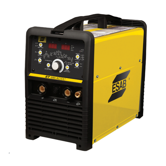
Art# A-13114 ESAB. Advice in this regard can be obtained by contacting an Accredited ESAB Distributor. Figure 2-1: ET 186i AC/DC Packaged System This equipment or any of its parts should not be altered from standard specification without prior written approval of ESAB. -
Page 11: Specifications
SAFE OPERATING REGION (TIG & STICK) 100 110 120 130 140 150 160 170 180 190 200 210 220 Welding Current (AMPS) A-11493 Figure 2-2: ET 186i AC/DC Duty Cycle 2.09 Specifications Description ESAB ET 186i AC/DC INVERTER Part Number... -
Page 12: Optional Accessories
Foot Control ..............Part No. W4013200 ESAB Helmet (USA Only) ......Part No. 4100-1004 2.11 Volt-Ampere Curves... -
Page 13: Installation, Operation And Setup
ESAB ET 186i AC/DC SECTION 3: INSTALLATION, OPERATION AND SETUP 3.01 Environment These units are designed for use in environments with WARNING increased hazard of electric shock as outlined in EN 60974.1. This equipment should be electrically con- Additional safety precautions may be required when using unit nected by a qualified electrician. -
Page 14: High Frequency Introduction
ESAB ET 186i AC/DC Attached to the power supply is an input power cord with a 208/230Volt 50 Amp NEMA 6-50 P for plug. WARNING An electrical shock or fire hazard is probable if the following electrical service guide recommendations are not followed. -
Page 15: Electromagnetic Compatibility
ESAB ET 186i AC/DC 3.07 Electromagnetic Compatibility WARNING Extra precautions for Electromagnetic Compatibility may be required when this Welding Power Source is used in a domestic situation. A. Installation and Use - Users Responsibility The user is responsible for installing and using the welding equipment according to the manufacturer’s instructions. If electromag- netic disturbances are detected then it shall be the responsibility of the user of the welding equipment to resolve the situation with the technical assistance of the manufacturer. -
Page 16: Et 186I Ac/Dc Power Source Controls, Indicators And Features
Selective screening and shielding of other cables and equipment in the surrounding area may alleviate problems of interference. Screening the entire welding installation may be considered for special applications. 3.08 ET 186i AC/DC Power Source Controls, Indicators and Features Art# A-13115... - Page 17 ESAB ET 186i AC/DC A-11232 Figure 3-2: Rear Panel 1. Positive Welding Terminal Positive Welding Terminal 2" (50mm) dinse. Welding current flows from the Power Source via heavy duty bayonet type terminals. It is essential, however, that the male plug is inserted and turned securely to achieve a sound electrical connection.
- Page 18 OFF the power source immediately to allow all components to cool down for at least 30 minutes. If after 30 minutes “Err 001” is displayed and Fault Indicator illuminates when the power source is switched back ON turn the power source OFF and have an Accredited ESAB Service Provider check the power source. 7. Process Selection Button The process selection control is used to select the desired welding mode.
- Page 19 ESAB ET 186i AC/DC High A-11409 Figure 3-3 4T Latch Mode This mode of welding is mainly used for long welding runs to reduce operator fatigue. In this mode the operator can press and release the torch trigger and the output will remain active. To deactivate the power source, the trigger switch must again be depressed and realized, thus eliminating the need for the operator to hold the torch trigger.
- Page 20 ESAB ET 186i AC/DC 12. Back Programming Button Pressing this button will go back to the previous step in the programming sequence. 13. AC frequency Indicator This indicator light will illuminate when programming AC Frequency (AC HF TIG mode only).
-
Page 21: Et 186I Ac/Dc - Stick Programming Mode
Power Source. 22. Cooling Fan The ET 186i AC/DC is fitted with a cooling fan that will operate continuously when the ON/OFF switch on the rear panel is switched to the ON position. - Page 22 ESAB ET 186i AC/DC Programming Parameter Adjustment Device Display Hot Start This parameter operates in all weld modes except LIFT TIG mode and is used to heat up the weld zone in TIG modes or improve the Amps start characteristics for stick electrodes the peak start current on top of the WELD current.
-
Page 23: Et Et 186I Ac/Dc - Lift Tig And Hf Tig Programming Mode
ESAB ET 186i AC/DC 3.10 ET ET 186i AC/DC – LIFT TIG and HF TIG Programming Mode Press the PROCESS SELECTION button to select LIFT TIG or HF TIG mode. Press the MODE switch to toggle between AC and DC welding output. - Page 24 ESAB ET 186i AC/DC Programming Parameter Adjustment Device Display Pre-Flow This parameter operates TIG modes only and is used to provide gas to the weld zone Volts prior to striking the arc, once the torch trigger switch has been 0.0 to 1.0 second pressed.
- Page 25 ESAB ET 186i AC/DC Programming Parameter Adjustment Device Display Low Current The lowest point in the pulse is called the Low Current. Amps 5 to 200A (DC HF TIG mode) 30 to 200A (AC LIFT TIG mode) 10 to 200A (AC HF TIG mode)
- Page 26 ESAB ET 186i AC/DC Programming Parameter Adjustment Device Display AC Frequency This parameter operates in AC TIG mode only and is used to set the frequency for the AC weld Volts current. 15 to 150 Hz Wave Balance This parameter operates in AC...
-
Page 27: Short Circuit Protection While Welding
ESAB ET 186i AC/DC 3.11 Short Circuit Protection While Welding To prolong the useful life of a TIG tungsten electrode and eliminate tungsten contamination to welding point, the ET 186i AC/DC incorporates special circuitry. In all TIG processes, after the welding arc has established, if the tungsten electrode touches the work the current defaults to 33 amps. - Page 28 ESAB ET 186i AC/DC A-09845_AB Figure 3-8: Regulator to Cylinder Valve 6. Before opening the cylinder valve, turn the regulator adjusting screw counterclockwise until there is no pressure on the adjusting spring and the screw turns freely. 7. Relief Valve (where provided): The relief valve is designed to protect the low pressure side of the regulator from high pres- sures.
-
Page 29: Specification For Tig Torch
ESAB ET 186i AC/DC 3.13 Specification for TIG Torch 1. SPECIFICATION FOR TIG TORCH PART NO: W4013600 TO SUIT ESAB ET 186iAC/DC TIG Torch Contents include: 1 x 26 TIG Torch with Long Back Cap, 12.5 ft lead length, 10.5" gas hose length, 9.5" control lead with 8 pin plug and Rigid Head. -
Page 30: Setup For Tig (Gtaw) Welding
E. Fit the welding grade shielding gas regulator/flowmeter to the shielding gas cylinder (refer to Section 3.12) then connect the shielding gas hose from the regulator/flowmeter outlet to the gas INLET on the rear of the ET 186i AC/DC Power Source. Connect the gas hose from the TIG torch to the gas OUTLET on the front of the ET 186i AC/DC Power Source. - Page 31 Figure 3-10: Setup for TIG Welding NOTE! When the ET 186i AC/DC is used with a Remote Foot Control in, depress foot control to maximum to al- low max current to be previewed/adjusted on the front panel. To avoid premature arcing, please ensure the TIG Torch is located away from your work piece.
-
Page 32: Setup For Stick (Smaw) Welding
16. You are now ready to begin TIG Welding. NOTE! When the ET 186i AC/DC is used with a Remote Foot Control in, depress foot control to maximum to al- low max current to be previewed/adjusted on the front panel. To avoid premature arcing, please ensure the TIG Torch is located away from your work piece. - Page 33 ESAB ET 186i AC/DC Negative Positive Welding Welding Terminal (+) Terminal (-) Art# A-13118 Electrode Holder Work Lead Figure 3-11: Setup for Manual Arc Welding. Manual 0-5425 3-21 INSTALLATION, OPERATION AND SETUP...
- Page 34 ESAB ET 186i AC/DC This Page Intentionally Blank INSTALLATION, OPERATION AND SETUP 3-22 Manual 0-5425...
-
Page 35: Basic Welding Guide
ESAB ET 186i AC/DC SECTION 4: BASIC WELDING GUIDE 4.01 STICK (SMAW) Basic Welding Technique Size of Electrode The electrode size is determined by the thickness of metals being joined and can also be governed by the type of welding machine available. - Page 36 ESAB ET 186i AC/DC Metal Being Joined Electrode Comments Mild Steel E6011 This electrode is used for all-position welding or for welding on rusty, dirty, less-than-new metal. It has a deep, penetrating arc and is often the first choice for repair or maintenance work.
-
Page 37: Fillet Joint
ESAB ET 186i AC/DC Joint Preparations In many cases, it will be possible to weld steel sections without any special preparation. For heavier sections and for repair work on castings, etc., it will be necessary to cut or grind an angle between the pieces being joined to ensure proper penetration of the weld metal and to produce sound joints. - Page 38 ESAB ET 186i AC/DC Striking the Arc Practice this on a piece of scrap plate before going on to more exacting work. You may at first experience difficulty due to the tip of the electrode "sticking" to the work piece. This is caused by making too heavy a contact with the work and failing to withdraw the electrode quickly enough.
- Page 39 ESAB ET 186i AC/DC Art # A-07698 Figure 4-12: Weld Build up Sequence Heavy plate will require several runs to complete the joint. After completing the first run, chip the slag out and clean the weld with a wire brush. It is important to do this to prevent slag being trapped by the second run. Subsequent runs are then deposited using either a weave technique or single beads laid down in the sequence shown in Figure 4-12.
- Page 40 ESAB ET 186i AC/DC C. Vertical Welds 2. Vertical Down Use a 1/8" (3.2mm) electrode at 100 amps. The tip 1. Vertical Up of the electrode is held in light contact with the work Tack weld a three feet length of angle iron to your and the speed of downward travel is regulated so that work bench in an upright position.
- Page 41 ESAB ET 186i AC/DC material is relatively weak, for example, a butt joint in 5/64" tion, although an unsuitable sequence may exaggerate it. (2.0mm) sheet, the contracting weld metal may cause the Simultaneous welding of both sides of a joint by two welders sheet to become distorted.
- Page 42 ESAB ET 186i AC/DC Art # A-07710_AB Block Sequence. The spaces between the welds are filled in when the welds are cool. Figure 4-24: Welding Sequence Art # A-07711_AB Figure 4-25: Step Back Sequence Art # A-07428_AB Figure 4-26: Chain Intermittent Welding...
-
Page 43: Stick (Smaw) Welding Troubleshooting
ESAB ET 186i AC/DC 4.02 STICK (SMAW) Welding Troubleshooting FAULT CAUSE REMEDY 1 Welding current ARC FORCE control knob Reduce the ARC FORCE control knob until varying is set at a value that causes welding current is reasonably constant while... - Page 44 ESAB ET 186i AC/DC FAULT CAUSE REMEDY 5 Portions of the A Small electrodes used on A Use larger electrodes and preheat the plate. weld run do not heavy cold plate. fuse to the surface B Welding current is too low.
-
Page 45: Tig (Gtaw) Basic Welding Technique
ESAB ET 186i AC/DC 4.03 TIG (GTAW) Basic Welding Technique Gas Tungsten Arc Welding (GTAW) or TIG (Tungsten Inert Gas) as it is commonly referred to, is a welding process in which fusion is produced by an electric arc that is established between a single tungsten (non-consumable) electrode and the work piece. Shield- ing is obtained from a welding grade shielding gas or welding grade shielding gas mixture which is generally Argon based. - Page 46 ESAB ET 186i AC/DC Tungsten Electrode Types Electrode Type Welding Application Features Color Code (Ground Finish) DC welding of mild Excellent arc starting, Thoriated 2% steel, stainless steel Long life, High current and copper carrying capacity High quality AC Self cleaning, Long...
-
Page 47: Tig (Gtaw) Welding Problems
ESAB ET 186i AC/DC 4.04 TIG (GTAW) Welding Problems FAULT CAUSE REMEDY 1 Excessive bead build up or Welding current is too Increase weld current and/or faulty joint poor penetration or poor preparation. fusion at edges of weld. 2 Weld bead too wide and Welding current is too Decrease weld current. - Page 48 ESAB ET 186i AC/DC FAULT CAUSE REMEDY 8 Poor weld finish Inadequate shielding Increase gas flow or check gas line for gas. gas flow problems. 9 Arc start is not smooth. A Tungsten electrode A Select the right size tungsten electrode.
-
Page 49: Section 5: Power Source Problems
If major complex subassemblies are faulty, then the Welding Power Source must be returned to an accredited ESAB Service Pro- vider for repair. The basic level of troubleshooting is that which can be performed without special equipment or knowledge. Refer also to section 4 for solving welding problems. -
Page 50: Routine Service And Calibration Requirements
There are extremely dangerous voltage and power levels present inside this Inverter Power Source. Do not attempt to open or repair unless you are an accredited ESAB Service Provider. Disconnect the Weld- ing Power Source from the Mains Supply Voltage before disassembling. - Page 51 2. The earth terminal of the associated plug of a transportable power source Note that due to the dangers of stray output currents damaging fixed wiring, the integrity of fixed wiring supplying ESAB welding power sources should be inspected by a licensed electrical worker in accordance with the requirements below - 1.
-
Page 52: Cleaning The Welding Power Source
B. Calibration Requirements Where applicable, the tests outlined in Table 5-3 below shall be conducted by an accredited ESAB service provider. Testing Requirements Output current (A) to be checked to ensure it falls within applicable ESAB power source specifications... -
Page 53: Key Spare Parts
ESAB ET 186i AC/DC SECTION 6: KEY SPARE PARTS 6.01 Power Source A-11500_AC Figure 6-1 Manual 0-5425 KEY SPARE PARTS... - Page 54 ESAB ET 186i AC/DC ET 186i AC/DC Spare Parts Item Part Number Description PCB display W7005500 PCB aux power supply W7005503 PCB HF W7005502 PCB 186ACDC W7005504 PCB AC output drive W7005505 PCB control W7005506 PCB secondary rectifier W7005507 W7005538...
-
Page 55: Appendix 1 : Circuit Diagram
ESAB ET 186i AC/DC APPENDIX 1 : CIRCUIT DIAGRAM Manual 0-5425 APPENDIX... -
Page 56: Appendix 2 : Et 186I Ac/Dc Setup Guide
Overlaminate: .see above Adhesive: 3M Grade 468 ESAB ET 186i AC/DC NOTES: Cutout (1) Indicated by color shown : APPENDIX 2 : ET 186i AC/DC SETUP GUIDE LIFT TIG / HF TIG SET-UP GUIDE POST SELECT TIG SELECT SELECT MODE... - Page 57 ESAB ET 186i AC/DC STICK SET-UP GUIDE 3/32" 1/8" 5/32" MODE ELECTRODE ELECTRODE SELECT (2.4 mm) (3.2 mm) (4.0 mm) SELECTION SELECTION DIAMETER PROCESS LIFT TIG / HF TIG Notes Gas is 100% Pure Argon. 50-75A 70-110A 80-145A Weld Current (Range)
- Page 58 ESAB ET 186i AC/DC This Page Blank Intentionally APPENDIX Manual 0-5425...
- Page 60 ESAB Asia/Pacific Pte Ltd ESAB Nederland B.V. Singapore Amersfoort Tel: +65 6861 43 22 Tel: +31 33 422 35 55 Fax: +65 6861 31 95 Fax: +31 33 422 35 44 www.esab.eu ©2015 ESAB Welding and Cutting Products Printed in China...
Need help?
Do you have a question about the ET 186i AC/DC and is the answer not in the manual?
Questions and answers