ESAB POWERCUT-1500 Instruction Manual
Plasma cutting system
Hide thumbs
Also See for POWERCUT-1500:
- Instruction manual (48 pages) ,
- Installation, operation and service manual (44 pages) ,
- Instruction manual (48 pages)
Table of Contents
Advertisement
Advertisement
Table of Contents
Troubleshooting

Related Manuals for ESAB POWERCUT-1500


Summary of Contents for ESAB POWERCUT-1500
- Page 1 POWERCUT-1500 Instruction Manual (GB) 0558003745 102002...
- Page 2 BE SURE THIS INFORMATION REACHES THE OPERATOR. YOU CAN GET EXTRA COPIES THROUGH YOUR SUPPLIER. These INSTRUCTIONS are for experienced operators. If you are not fully familiar with the principles of operation and safe practices for arc welding and cutting equipment, we urge you to read our booklet, "Precautions and Safe Practices for Arc Welding, Cutting, and Gouging,"...
- Page 3 SAFETY Full responsibility for safety of personnel working on or near system rests on user of ESAB Welding Equipment. Wrong operation can lead to abnormal situation, injure operator and damage equipment. All personnel working with welding equipment must be fully familiar with...
- Page 4 SAFETY ! WARNING ! ARC WELDING AND CUTTING CAN BE INJURIOUS TO YOURSELF AND OTHERS. TAKE PRECAUTIONS WHEN WELDING OR CUTTING. ASK YOUR EMPLOYER FOR SAFETY PRACTICES THAT SHOULD BE BASED ON MANUFACTURER’S HAZARD DATA. ELECTRIC SHOCK - Can kill - Install and earth welding equipment in accordance with obligatory standards.
-
Page 5: Table Of Contents
Primary Electrical Input Connections ..............89 Secondary Output Connections ................ 91 SECTION 3 OPERATION ....................93 Operation ......................93 PowerCut-1500 Controls .................. 93 Cutting with the PT-32EH ................. 95 Possible Cutting Issues ..................98 SECTION 4 MAINTENANCE ....................161 General ......................161 Inspection and Cleaning ................... -
Page 7: Description
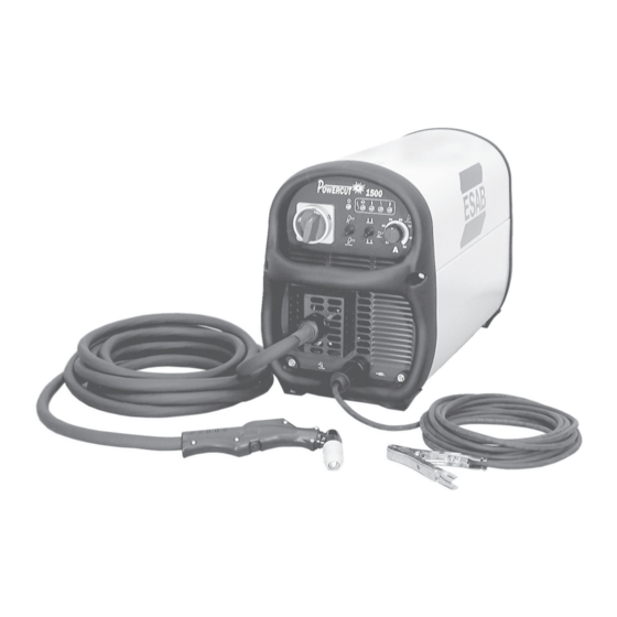
Powercut 1500 Manual Cutting Packages: PowerCut-1500 400 V, "CE" 7.6 m (25 ft.) PT-32EH .... P/N 0558001945 PowerCut-1500 400 V, "CE" 15.2 m (50 ft.) PT-32EH ..P/N 0558001946 The components that are included in the Powercut-1500 packages may be purchased separately by using the appropriate P/N when placing orders. -
Page 8: Specifications
SECTION 1 DESCRIPTION 1.4 SPECIFICATIONS Table 1-2 PowerCut-1500 Specifications Rated Inputs Rated Outputs Open Power * Duty Output Phases Volts Amps Circuit Efficiency Factor Cycle Amps Voltage 90A @ 127Vdc 278 Vdc Three 100% 75A @ 120Vdc 278 Vdc Length 648 mm (25.50") - Page 9 6.4 (1/4) 457 (18) 9.5 (3/8) 254 (10) 12.7 (1/2) 152 (6) Aluminum 1.6 (1/16) 5,080 (200) 3.2 (1/8) 2,794 (110) 6.4 (1/4) 1,219 (48) 9.5 (3/8) 432 (17) 12.7 (1/2) 356 (14) Figure 1-2 PT-32EH / POWERCUT-1500 Cutting Performance...
-
Page 11: Installation
SECTION 2 INSTALLATION 2.1 GENERAL Proper installation is important for satisfactory and trouble-free operation of the PowerCut 1500 cutting package. It is suggested that each step in this section be studied carefully and followed closely. 2.2 EQUIPMENT REQUIRED A source of clean, dry air that supplies 165 l/m (350 cfh) at 5.5 bar (80 psig) is required for the cutting operation. - Page 12 SECTION 2 INSTALLATION 2.5.1 INPUT VOLTAGE CHANGEOVER ELECTRIC SHOCK CAN KILL! A line (wall) disconnect switch with fuses or circuit breakers should be Before making electrical input provided at the main power panel (see table below for fuse sizes). The connections to the power input power cable of the console may be connected directly to the discon- source, "Machinery Lockout...
- Page 13 SECTION 2 INSTALLATION 2.6 SECONDARY (OUTPUT) CONNECTION (REFER TO FIGURE BELOW) The torch comes factory installed. Connect your air supply to the inlet connection of the filter-regulator. Prefiltered DRY AIR SUPPLY (Customer Supplied) 6.2 to 10.3 bar (90 to 150 psig max) PRIMARY INPUT POWER CABLE FUSED...
-
Page 15: Operation
SECTION 3 OPERATION Figure 3-1A PowerCut 1500 Controls 3.1 OPERATION 3.2 PowerCut 1500 CONTROLS (see figure above) Power Switch. When placed in ON position, the green pilot light will glow indicating control circuit is energized. Air Test Switch. When placed in Test position, air filter-regulator can be adjusted to desired pressure 5.5 bar (80 psig) before cutting operations. - Page 16 SECTION 3 OPERATION Figure 3-1B PowerCut 1500 Controls 3.2 PowerCut 1500 Indicator Lights (see figure above) E. Power "ON" Indicator: Illuminates whenever the front panel power switch is in the ON position. F. AC Line Indicator or High/Low Line Voltage Indicator: This fault light will blink to indicate that the input voltage is outside the “+ or -”...
- Page 17 SECTION 3 OPERATION 3.3 CUTTING WITH THE POWERCUT-1500 Use the following procedures to cut with the PT-32EH torch (see ex- ploded view of PT-32EH torch). ELECTRIC SHOCK can kill. ž Do NOT operate the unit with Make sure that the wall disconnect switch is on. Turn on the front panel the cover removed.
- Page 18 SECTION 3 OPERATION When ending a cut, the torch switch should be released (press and release if using trigger LOCK mode) and the torch lifted off the workpiece just before the end of the cut. This is to prevent the high frequency from reigniting after cutting arc extinguishes and causing damage to the nozzle (double arcing).
-
Page 19: Operation Section
SECTION 3 OPERATION ADJUST GUIDE BY TURNING IN A CLOCKWISE DIRECTION ONLY. THIS WILL PREVENT ACCIDENTAL LOOSENING OF SHIELD. STEEL GUARD STAND OFF GUIDE P/N 0558002393 IF GUIDE IS TOO TIGHT ON SHIELD, OPEN SLOT WITH SCREWDRIVER. THIN GAUGE MATERIALS GUIDE AGAINST CAN BE CUT WITH 1.6 mm (1/16") STRAIGHT EDGE... -
Page 20: Possible Cutting Issues
If drag cutting is desired for thin material under 9.5 mm (3/8") thick, remove Drag cutting, even with lower the standard 90 amp nozzle from the PT-32EH torch and install ESAB's 40 current levels may significantly amp nozzle. Lower the current level setting to be within the AUTO- reduce the life of torch DRAG range of 20 to 40 amps (see Auto Drag Scale on front panel). - Page 21 If problems are determined to be caused by the PowerCut 1500, refer to the maintenance section of this manual. If the problem is not corrected after referring to the maintenance section, contact your ESAB distributor. A. Insufficient Penetration.
-
Page 23: Maintenance
Make sure all plugs, fittings, and ground connections are tight. With all input power disconnected, and wearing proper eye and face protection, blow out the inside of the Powercut-1500 using low- pressure dry compressed air. Water or oil occasionally accumulates in compressed air lines. Be sure to direct the first blast of air away from the equipment to avoid damage to the Powercut-1500. -
Page 24: Igbt Handling & Replacement
SECTION 4 MAINTENANCE 4.4 IGBT Handling & Replacement Since IGBT gates are insulated from any other conducting region, care should be taken to prevent static build up, which could possibly damage gate oxides. All IGBT modules are shipped from the factory with conduc- tive foam contacting the gate and emitter sense pins. -
Page 25: Troubleshooting
SECTION 5 TROUBLESHOOTING 5.1 TROUBLESHOOTING ELECTRIC SHOCK CAN KILL! Be sure that all primary power to the machine has been externally disconnected. Open the line (wall) disconnect switch or circuit breaker before attempting inspection or work inside of the power source. Check the problem against the symptoms in the following troubleshooting guide. -
Page 26: Troubleshooting Guide
SECTION 5 TROUBLESHOOTING 5.2 TROUBLESHOOTING GUIDE A. Power Light does not come on. 1. Visually inspect the machine for any damage. 2. Check following: a. Check if the machine power cord is plugged into the input power receptacle. b. Measure the input power at the receptacle. If not present, then check the wall disconnect switch and it’s fuses. - Page 27 D. Fault light activates when torch switch is closed. The machine monitor conditions necessary for the safe operation of the Powercut-1500. The fault lights will glow under the following conditions and operations will come to a stop. 1. High/Low line voltage. The "AC LINE" light will blink to indicate that the input voltage is outside the +/- 15% range of the nominal voltage.
- Page 28 SECTION 5 TROUBLESHOOTING c. To check if the output is shorted, measure the resistance by putting the ohmmeter leads across the output. Put the black lead to the "work" terminal and the red lead to the torch electrode terminal. The reading should be about 2K OHMs. b.
- Page 29 SECTION 5 TROUBLESHOOTING F. High Frequency and Pilot Arc are on but Main Arc does not transfer. 1. Make sure work clamp is connected to work material. 2. Check the torch. Replace consumables if necessary. G. Poor Cutting Performance. 1. Check air supply regulator . It should be adjusted to 80 psig. 2.
- Page 30 SECTION 5 TROUBLESHOOTING 5.3 REFERENCE VOLTAGE CHECKS A. Control Board Assembly (PCB1) LED’s LED- (D9)- Torch Switch LED- (D4)- Pilot Arc Relay LED- (D1)- Gas Solenoid Valve Voltage Test Points Tests are made with power on - no arc. Disable High Frequency by disconnecting blue wire with black sleeve TP-1 - Torch trigger signal TP-4 - IGBT’s driving signal - switching frequency = 18.5 KHz...
- Page 31 SECTION 5 TROUBLESHOOTING 5.4 SEQUENCE OF OPERATION A. TRIGGER LOCK “UNLOCK” position PUSH RELEASE TORCH SWITCH OPEN CLOSE GAS SOLENOID VALVE PREFLOW 20 SEC 2 SEC. Postflow OPEN FLOW SWITCH CLOSE FAULT OVERLOAD LIGHT HF CIRCUIT ENERGIZE PILOT ARC INVERTER CUTTING ARC (CURRENT) NOTES: When the torch switch is pushed during postflow period, the postflow and preflow times are canceled, and the...
- Page 32 SECTION 5 TROUBLESHOOTING TRIGGER LOCK "LOCK" position PUSH RELEASE PUSH RELEASE TORCH SWITCH OPEN CLOSE GAS SOLENOID VALVE PREFLOW 2 SEC. 20 SEC Postflow POSTFLOW CLOSE OPEN FLOW SWITCH FAULT LIGHT ENERGIZE HF CIRCUIT PILOT ARC INVERTER CUTTING ARC (CURRENT) NOTES: When the torch switch is pushed during postflow period, the postflow time is reset, the preflow time is canceled, and the HF is energized immediately.
-
Page 35: Replacement Parts
B. ORDERING To assure proper operation, it is recommended that only genuine ESAB parts and products be used with this equipment. The use of non-ESAB parts may void your warranty. Replacement parts may be ordered from your ESAB distributor or from: ESAB Welding &... - Page 36 SECTION 6 REPLACEMENT PARTS Front View - Powercut-1500 Item Part Qty. Description Symbol 0558003359 Switch, Power 0558000596 Switch Seal, Black 0558001818 Knob 0558003770 Panel Front Silkscreen 0558003001 Work Cable Assembly 0558003771 Work Cable Receptacle 0558002780 Foot, Plasma Tube 0558002581 Strain Relief Input NPT...
- Page 37 SECTION 6 REPLACEMENT PARTS Rear View - Powercut-1500 Item Part Qty. Description Symbol 0558000675 Regulator, Air Line 0558000594 Gauge, 160 PSI 0558003362M Panel, Rear 0558003075 Fuse, 2A, 600VAC 0558003774 Connector Cable Grip 0558003554 Cable, Input Power x 10 ft. 0558000388...
- Page 38 SECTION 6 REPLACEMENT PARTS Internal View - Powercut-1500 Lower Left Side Item Part Qty. Description Symbol 0558003377 Transformer, Main Module T2, T4 0558000404 RES WWFAHT 25W 1% 20 OHMS R12-15 0558000401 Diode Module FDS 100A 600V D7, D8 0558003367 Transducer Current 100A...
- Page 39 SECTION 6 REPLACEMENT PARTS (Behind Bar) (Behind 6) (Behind Power PCB) (Behind Bar) Internal View - Powercut-1500 Right Side Item Part Qty. Description Symbol 0558000643 3PH BR Rect. w/out Thyristor 0558003182 Module Dual IGBT 200A 600V Q2, Q3 0558003779 RES WW AHNI 50W 3%K 10 OHM...
- Page 40 SECTION 6 REPLACEMENT PARTS Internal View - Powercut-1500 Item Part Qty. Description Symbol 0558003785 PCB Start-up Network PCB6 0558003786 PCB Display PCB3 0558003787 PCB Control PCB1 0558003788 Solid State Relay 0558003789 PCB In Rush Control PCB4 0558003790 Switch Thermal 131°F...
- Page 41 Instruction Manual Changes ORIGINAL RELEASE...
- Page 42 ESAB subsidiaries and representative offices Europe NORWAY Asia/Pacific Representative offices AS ESAB AUSTRIA AUSTRALIA BULGARIA Larvik ESAB Ges.m.b.H ESAB Australia Pty Ltd ESAB Representative Office Tel: +47 33 12 10 00 Vienna--Liesing Ermington Sofia Fax: +47 33 11 52 03...
Need help?
Do you have a question about the POWERCUT-1500 and is the answer not in the manual?
Questions and answers