ESAB POWERCUT-1500 Instruction Manual
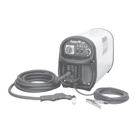
Plasma arc cutting package
Hide thumbs
Also See for POWERCUT-1500:
- Instruction manual (42 pages) ,
- Installation, operation and service manual (44 pages) ,
- Instruction manual (48 pages)

Related Manuals for ESAB POWERCUT-1500


Summary of Contents for ESAB POWERCUT-1500
- Page 1 POWERCUT-1500 PLASMA ARC CUTTING PACKAGE Be sure this information reaches the operator. You can get extra copies through your supplier. F15-695-C 10 / 2003...
-
Page 2: User Responsibility
BE SURE THIS INFORMATION REACHES THE OPERATOR. YOU CAN GET EXTRA COPIES THROUGH YOUR SUPPLIER. These INSTRUCTIONS are for experienced operators. If you are not fully familiar with the principles of operation and safe practices for arc welding and cutting equipment, we urge you to read our booklet, "Precautions and Safe Practices for Arc Welding, Cutting, and Gouging,"... -
Page 3: Table Of Contents
Primary Electrical Input Connections ..............13 Secondary Output Connections ................. 15 SECTION 3 OPERATION ..................... 16 Operation ......................16 PowerCut-1500 Controls ................... 16 Cutting with the PT-32 ..................18 Possible Cutting Issues ..................21 SECTION 4 MAINTENANCE ....................22 General ......................22 Inspection and Cleaning .................. -
Page 4: Safety Precautions
SECTION 1 SAFETY PRECAUTIONS hese Safety Precautions are for WARNING: 5. Do not use equipment beyond its ratings. For example, your protection. They summarize precaution- overloaded welding cable can overheat and create a fire ary information from the references listed in hazard. - Page 5 SECTION 1 SAFETY PRECAUTIONS EQUIPMENT MAINTENANCE -- Faulty or FUMES AND GASES -- Fumes and improperly maintained equipment can gases, can cause discomfort or harm, cause injury or death. Therefore: particularly in confined spaces. Do not breathe fumes and gases. Shield- 1.
- Page 6 SECTION 1 PRECAUCION DE SEGURIDAD el calor causado por cable sobrecarga en los cables de soldar Estas Precauciones de Seguridad ADVERTENCIA: pueden ocasionar un fuego. son para su protección. Ellas hacen resumen de 6. Después de termirar la operación del equipo, inspeccione el área información proveniente de las referencias listadas de trabajo para cerciorarse de que las chispas o metal caliente en la sección "Información Adicional Sobre La Seguridad".
- Page 7 SECTION 1 PRECAUCION DE SEGURIDAD HUMO Y GASES -- El humo y los gases, MANTENIMIENTO DEL EQUIPO -- Equipo pueden causar malestar o daño, defectuoso o mal mantenido puede causar particularmente en espacios sin daño o muerte. Por lo tanto: ventilación.
- Page 8 SECTION 1 PRÉCAUTIONS DE SÉCURITÉ provoquer de graves incendies au contact de AVERTISSEMENT: Ces règles de sécurité ont pour objet matériaux combustibles solides, liquides ou gazeux. d’ assurer votre protection. Veillez à lire et à observer les Aussi faut-il observer les précautions suivantes: précautions énoncées ci-dessous avant de monter l’...
- Page 9 52529 “Precautions and Safe Practices for Arc fonctionne que si l’interrupteur correspondant du Welding, Cutting and Gouging” publié par ESAB. panneau avant se trouve placé en position ON Nous conseillons également de consulter les (Marche).
-
Page 10: Description
■ Multiple troubleshooting lights on front panel ■ Superior gouging performance Torch ■ Three year warranty on console. PowerCut-1500 uses the PT-32EH torch. For complete list ■ One year warranty on torch. and breakdown of parts, refer to PT-32 data page. Specifications: PowerCut-1500 Ordering Information: Cuts 1-1/2 in. -
Page 11: Optional Accessories
40 amp Drag Nozzle ..........0558002908 Gouging Nozzle ............0558003089 Heat Shield Gouging ..........0558003090 The PowerCut-1500 comes out of the box ready to go. The torch is Drag Heat Shield ............0558003374 attached with parts in place, primary cord is attached (including plug on 230 model), and the filter/regulator is installed. -
Page 12: General
(90-150 psi). not designed for use with this console The Powercut-1500 package uses the heavy-duty PT-32 torch to deliver cutting could create an ELECTRIC SHOCK power for severing materials up to 1-1/2 inch thick. Refer to the following HAZARD. -
Page 13: Installation
SECTION 2 INSTALLATION 2.1 GENERAL Proper installation is important for satisfactory and trouble-free operation of the PowerCut 1500 cutting package. It is suggested that each step in this section be studied carefully and followed closely. 2.2 EQUIPMENT REQUIRED A source of clean, dry air that supplies 350 cfh at 80 psig is required for the cutting operation. - Page 14 2.5.1 INPUT VOLTAGE CHANGEOVER 200 - 230 or 460 Mode To simplify the use of the ESAB Powercut 1500 with different input volt- Before making any connections to the ages, it has been equipped with a convenient 230/460 selector switch lo- power source output terminals, make cated on the back panel of the unit.
-
Page 15: Secondary Output Connections
SECTION 2 INSTALLATION 2.6 SECONDARY (OUTPUT) CONNECTIONS (REFER TO FIG. 2-1) The Torch comes factory installed. Figure 2-1. PowerCut 1500 Interconnection Diagram Connect your air supply to the inlet connection of the filter-regulator. Prefiltered DRY AIR SUPPLY (Customer Supplied) (90 to 150 psig max) PRIMARY INPUT POWER CABLE FUSED... -
Page 16: Operation
SECTION 3 OPERATION Figure 3-1A. PowerCut 1500 Controls 3.1 OPERATION 3.2 PowerCut 1500 CONTROLS (FIGURE 3-1A) Power Switch. When placed in ON position, the green pilot light will glow indicating control circuit is energized. Air Test Switch. When placed in Test position, air filter-regulator can be adjusted to desired pressure (80 psig) before cutting operations. - Page 17 SECTION 3 OPERATION Figure 3-1B. PowerCut 1500 Controls 3.2 PowerCut 1500 Indicator Lights (FIGURE 3-1B) E. Power "ON" Indicator: Illuminates whenever the front panel power switch is in the ON position. F. AC Line Indicator or High/Low Line Voltage Indicator: This fault light will blink to indicate that the input voltage is outside the “+ or -”...
- Page 18 SECTION 3 OPERATION turned back on. 3.3 CUTTING WITH THE POWERCUT-1500 Use the following procedures to cut with the PT-32 torch (Figure 3-4). ELECTRIC SHOCK can kill. • Do NOT operate the unit with the Make sure that the wall disconnect switch is on. Turn on the Front Panel cover removed.
- Page 19 SECTION 3 OPERATION held approximately 1/4 inch from the work. When ending a cut, the torch switch should be released (press and release if using trigger LOCK mode) and the torch lifted off the workpiece just before the end of the cut. This is to prevent the high frequency from reigniting after cutting arc extinguishes and causing damage to the nozzle (double arcing).
-
Page 20: Operation Section
SECTION 3 OPERATION ADJUST GUIDE BY TURNING IN A CLOCKWISE DIRECTION ONLY. THIS WILL PREVENT ACCIDENTAL LOOSENING OF SHIELD. STEEL GUARD STAND OFF GUIDE P/N 0558002393 IF GUIDE IS TOO TIGHT ON SHIELD, OPEN SLOT WITH SCREWDRIVER. THIN GAUGE MATERIALS GUIDE AGAINST CAN BE CUT WITH 1/16"... -
Page 21: Possible Cutting Issues
If drag cutting is desired for thin material under 3/8" thick, remove the standard Drag cutting, even with lower current 90 amp nozzle from the PT-32 torch and install ESAB's 40 amp nozzle (P/N levels may significantly reduce the life of torch consumables. -
Page 22: Section 4 Maintenance
If problems are determined to be caused by the PowerCut 1500, refer to the maintenance section of this manual. If the problem is not corrected after referring to the maintenance section, contact your ESAB distributor. A. Insufficient Penetration. -
Page 23: Maintenance
Make sure all plugs, fittings, and ground connections are tight. With all input power disconnected, and wearing proper eye and face protection, blow out the inside of the Powercut-1500 using low-pressure dry compressed air. Water or oil occasionally accumulates in compressed air lines. Be sure to direct the first blast of air away from the equipment to avoid damage to the Powercut-1500. - Page 24 If drag cutting is desired on materials above 3/8” thick, be sure that the 90 amp nozzle (P/N 0558002837) is installed in the PT-32 torch. Attach ESAB's stand-off guide (P/N 0558002393) and operate as shown in Figure 3.4. PLACE THE VALVE PIN INTO THE...
-
Page 25: Igbt Handling & Replacement
SECTION 4 MAINTENANCE 4.4 IGBT Handling & Replacement Since IGBT gates are insulated from any other conducting region, care should be taken to prevent static build up, which could possibly damage gate oxides. All IGBT modules are shipped from the factory with conduc- tive foam contacting the gate and emitter sense pins. - Page 26 SECTION 4 MAINTENANCE Two-Point Mounting Type Temporary tightening Final tightening Four-Point Mounting Type Temporary tightening Final tightening Figure 4-2. Screw Fastening Order...
-
Page 27: Troubleshooting
SECTION 5 TROUBLESHOOTING 5.1TROUBLESHOOTING ELECTRIC SHOCK CAN KILL! Be sure that all primary power to the machine has been externally disconnected. Open the line (wall) disconnect switch or circuit breaker before attempting inspection or work inside of the power source. Check the problem against the symptoms in the following troubleshooting guide. -
Page 28: Troubleshooting
SECTION 5 TROUBLESHOOTING 5.2TROUBLESHOOTING GUIDE A. Power Light does not come on. 1. Visually inspect the machine for any damage. 2. Check following: a. Check if the machine power cord is plugged into the input power receptacle. b. Measure the input power at the receptacle. If not present, then check the wall disconnect switch and it’s fuses. - Page 29 D. Fault light activates when torch switch is closed. The machine monitor conditions necessary for the safe operation of the Powercut-1500. The fault lights will glow under the following conditions and operations will come to a stop. 1. High/Low line voltage. The "AC LINE" light will blink to indicate that the input voltage is outside the +/- 15% range of the nominal voltage.
- Page 30 SECTION 5 TROUBLESHOOTING c. To check if the output is shorted, measure the resistance by putting the ohmmeter leads across the output. Put the black lead to the "work" terminal and the red lead to the torch electrode terminal. The reading should be about 2K OHMs. b.
- Page 31 SECTION 5 TROUBLESHOOTING F. High Frequency and Pilot Arc are on but Main Arc does not transfer. 1. Make sure work clamp is connected to work material. 2. Check the torch. Replace consumables if necessary. G. Poor Cutting Performance. 1. Check air supply regulator . It should be adjusted to 80 psig. 2.
- Page 32 SECTION 5 TROUBLESHOOTING 5.3 REFERENCE VOLTAGE CHECKS A. Control Board Assembly (PCB1) LED’s LED- (D9)- Torch Switch LED- (D4)- Pilot Arc Relay LED- (D1)- Gas Solenoid Valve Voltage Test Points Tests are made with power on - no arc. Disable High Frequency by disconnecting blue wire with black sleeve TP-1 - Torch trigger signal TP-4 - IGBT’s driving signal - switching frequency = 18.5 KHz...
- Page 33 SECTION 5 TROUBLESHOOTING 5.4 SEQUENCE OF OPERATION A. TRIGGER LOCK “UNLOCK” position PUSH RELEASE TORCH SWITCH OPEN CLOSE GAS SOLENOID VALVE PREFLOW 2 SEC. 20 SEC Postflow OPEN FLOW SWITCH CLOSE FAULT OVERLOAD LIGHT HF CIRCUIT ENERGIZE PILOT ARC INVERTER CUTTING ARC (CURRENT) NOTES: When the torch switch is pushed during postflow period, the postflow and preflow times are canceled, and the...
- Page 34 SECTION 5 TROUBLESHOOTING TRIGGER LOCK "LOCK" position PUSH RELEASE PUSH RELEASE TORCH SWITCH OPEN CLOSE GAS SOLENOID VALVE PREFLOW 2 SEC. 20 SEC Postflow OPEN CLOSE FLOW SWITCH FAULT LIGHT ENERGIZE HF CIRCUIT PILOT ARC INVERTER CUTTING ARC (CURRENT) NOTES: When the torch switch is pushed during postflow period, the postflow time is reset, the preflow time is canceled, and the HF is energized immediately.
-
Page 36: Replacement Parts
B. ORDERING To assure proper operation, it is recommended that only genuine ESAB parts and products be used with this equipment. The use of non-ESAB parts may void your warranty. Replacement parts may be ordered from your ESAB distributor or from: ESAB Welding &... - Page 37 SECTION 6 REPLACEMENT PARTS 9, 10 Front View - Powercut-1500 Item Part Qty. Description Symbol 36107 SW Pwr Disc 600V 951474 Switch Seal Black 954942 Overlay Front Panel Powercut-1500 0558001818 Knob 1.37 Diam 0558002461M Panel Front 0558003001 Work Cable #6 AWG...
- Page 38 SECTION 6 REPLACEMENT PARTS Rear View - Powercut-1500 Item Part Qty. Description Symbol 21710 Regulator Air Line *808-02 21711 Gauge 1.50 *160 PSI WHT CB 0558002446 Switch 40A 0558003075 Fuse 2A 600VAC, Fast Acting Only 97W63 Connector Cable Grip 0558003002 Cable Input Power, 10Ft.
- Page 39 SECTION 6 REPLACEMENT PARTS Internal View - Powercut-1500 Lower Left Side Item Part Qty. Description Symbol 0558002447 Transformer Main T2, T4 17721020 RES WWFAHT 25W 1% 20 OHMS R12-15 951185 Diode Module FDS 100A 600V D7, D8 952252 Transducer Current 100A...
- Page 40 SECTION 6 REPLACEMENT PARTS Internal View - Powercut-1500 Left Side Rear Item Part Qty. Description Symbol 0558002482 SOL AY 1/8 NPTF Port 3/16 BARB SOL1 0558002189 Switch Pressure .25 GPN 0558003105 Switch Pressure High...
- Page 41 SECTION 6 REPLACEMENT PARTS Internal View - Powercut-1500 Left Side Sub-Assembly Item Part Qty. Description Symbol 0558002446 Switch 40A 0558002435 CAP 3100 UF 450VDC Alum C5, C6 36107 SW PWR* Disc 600V...
- Page 42 SECTION 6 REPLACEMENT PARTS Internal View - Powercut-1500 Right Side Item Part Qty. Description Symbol 0558002434 3PH BR Rect. w/out Thyristor 17750050 RES WW 50W 50 OHM 0558003182 Module Dual IGBT 200A 600V Q2, Q3 17750051 RES WW AHNI 50W 3%K 10 OHM...
- Page 43 SECTION 6 REPLACEMENT PARTS (Located Under Lip) Internal View - Powercut-1500 Right Side Sub-Assembly Item Part Qty. Description Symbol 17712502 RES WW AH** TT *25W *3% 5K OHMs R8 - 11 0558002448 Transformer Control 0558002438 Inductor Input 0558002449 Transformer Hi Frequency...
- Page 44 SECTION 6 REPLACEMENT PARTS Upper Left Side Internal View - Powercut-1500 Item Part Qty. Description Symbol 38180 PCB Control PCB1 952938 SCR 480V 18A Panel MNT 38208 PCB SCR Trigger PCB4 950710 Switch Thermal 131°F 951818 Relay SS 3—32VDC/24—28VAC 25A...
- Page 45 SECTION 6 REPLACEMENT PARTS Internal View - Powercut-1500 Front Left Side Item Part Qty. Description Symbol 38131 PCB Start-up Network PCB6 38172 PCB Display PCB3...
- Page 47 Instruction Manual Changes The "A" edition (3/02) of the manual covers the following: 1. Schematic Diagram upgraded from 0558003108 to 0558003108-A. 2. PCB Start-Up Network (P/N 38200) replaced with (P/N 38131) in parts list on page 34. Revision C = Added P/N 950435 (Locknut) to Replacement Parts Page 37 - 10 / 2003...
- Page 48 ESAB Welding & Cutting Products, Florence, SC Welding Equipment COMMUNICATION GUIDE - CUSTOMER SERVICES A. CUSTOMER SERVICE QUESTIONS: Telephone: (800)362-7080 / Fax: (800) 634-7548 Order Entry Product Availability Pricing Delivery Order Changes Saleable Goods Returns Shipping Information Hours: 8:00 AM to 7:00 PM EST B.
Need help?
Do you have a question about the POWERCUT-1500 and is the answer not in the manual?
Questions and answers