
Related Manuals for ESAB ROGUE EM 140


Summary of Contents for ESAB ROGUE EM 140
- Page 1 Rogue EM 140 Instruction manual Valid for: Serial number: HA302-xxxx-xxxx 0447 955 001 US 20230719...
-
Page 2: Table Of Contents
Power source and wire feeder maintenance ..................Torch and liner maintenance .......................... ERROR CODES ....................Error code descriptions ........................ TROUBLESHOOTING ....................... ORDERING SPARE PARTS ..........................WIRING DIAGRAM ......................... ORDERING NUMBERS ............................WEAR PARTS ............................. ACCESSORIES 0447 955 001 - 2 - © ESAB AB 2023... -
Page 3: Safety
7. Use goggles over safety glasses when chipping slag or grinding. Chipped slag may be hot and can fly for long distances. Bystanders should also wear goggles over safety glasses. 0447 955 001 - 3 - © ESAB AB 2023... - Page 4 ELECTRIC AND MAGNETIC FIELDS May be dangerous. Electric current flowing through any conductor causes localized Electric and Magnetic Fields (EMF). Welding and cutting current creates EMF around welding cables and welding machines. Therefore: 0447 955 001 - 4 - © ESAB AB 2023...
- Page 5 1. Keep all doors, panels, guards, and covers closed and securely in place. 2. Stop the engine or drive systems before installing or connecting a unit. 3. Have only qualified people remove covers for maintenance and troubleshooting as necessary 0447 955 001 - 5 - © ESAB AB 2023...
- Page 6 NFPA Standard 51B, “Fire Prevention During Welding, Cutting, and Other Hot Work" • CGA Standard P-1, “Precautions for Safe Handling of Compressed Gases in Cylinders” • ANSI Z87.1, "Occupational and Educational Personal Eye and Face Protection Devices" 0447 955 001 - 6 - © ESAB AB 2023...
-
Page 7: User Responsibility
1 SAFETY User responsibility Users of ESAB equipment have the ultimate responsibility for ensuring that anyone who works on or near the equipment observes all the relevant safety precautions. Safety precautions must meet the requirements that apply to this type of equipment. The following recommendations should be observed, in addition to the standard regulations that apply to the workplace. - Page 8 • To handle hot parts, use proper tools and/or insulated welding gloves to prevent burns. MALFUNCTION - Call for expert assistance in the event of malfunction. PROTECT YOURSELF AND OTHERS! 0447 955 001 - 8 - © ESAB AB 2023...
-
Page 9: California Proposition 65 Warning
This product is solely intended for arc welding. ESAB has an assortment of welding accessories and personal protection equipment for purchase. For ordering information contact your local ESAB dealer or visit us on our website. California proposition 65 warning WARNING! Welding or cutting equipment produces fumes or gases which contain chemicals known in the State of California to cause birth defects and, in some cases, cancer. -
Page 10: Introduction
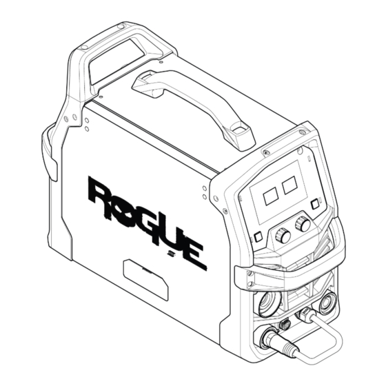
2 INTRODUCTION INTRODUCTION The Rogue EM 140 is a self-contained single phase welding system that is capable of performing GMAW (MIG) welding. ESAB accessories for the product can be found in the "ACCESSORIES" chapter of this manual. Equipment Rogue EMP 140 is supplied with: •... -
Page 11: Technical Data
The IP code indicates the enclosure class, i.e. the degree of protection against penetration by solid objects or water. Equipment marked IP23S is intended for indoor and outdoor use; however, it should not be operated in precipitation. 0447 955 001 - 11 - © ESAB AB 2023... - Page 12 3 TECHNICAL DATA Application class The symbol indicates that the power source is designed for use in areas with increased electrical hazard. 0447 955 001 - 12 - © ESAB AB 2023...
-
Page 13: Installation
Remove any packaging material prior to use. Do not block the air vents at the front or rear of the welding power source Location Position the power source so that cooling air inlets and outlets are not obstructed. A. Minimum 8 in. (200 mm) B. Minimum 8 in. (200 mm) 0447 955 001 - 13 - © ESAB AB 2023... -
Page 14: Lifting Instructions
Disconnect input power and secure employing 'Lock-out' / 'Tagging' procedures. Ensure input power line disconnect switch is locked (Lock-out/Tagging) in the 'Open' position BEFORE removing input power fuses. Connection/Disconnect should be carried out by competent persons. 0447 955 001 - 14 - © ESAB AB 2023... -
Page 15: Recommended Fuse And Cable Sizes
Generators with Automatic Voltage Regulation (AVR) or with an equivalent or better type of regulation, with rated power 6 kW, are recommended. 0447 955 001 - 15 - © ESAB AB 2023... -
Page 16: Operation
WARNING! Make sure the side panels are closed during operation. WARNING! Tighten the spool locking nut in order to prevent it from sliding off the hub. 4 in. (100 mm) 8 in. (200 mm) 0447 955 001 - 16 - © ESAB AB 2023... -
Page 17: Connections
The power source is delivered with the polarity changeover cable free hanging and not connected to the positive or negative weld terminals. Some wires, e.g. self-shielded cored wires, are recommended to be welded with negative polarity. 0447 955 001 - 17 - © ESAB AB 2023... -
Page 18: Drive System Diagram
MIG gun require a control wire assembly to connect the trigger leads to the unit. The control wire assembly is located near the power pin and plugs into the remote control receptacle. WARNING! The mains supply must be disconnected during installation. 0447 955 001 - 18 - © ESAB AB 2023... - Page 19 4) Locate the control wire assembly, align keyway with the key on the remote control receptacle, insert plug, and rotate threaded collar fully clockwise. 1. Thumb screw 2. Torch receptacle 0447 955 001 - 19 - © ESAB AB 2023...
-
Page 20: Inserting And Replacing Wire
8) With the GMAW torch lead reasonably straight, feed the wire through the GMAW torch by depressing the wire inch button or trigger switch. 9) Close the spool side door. Welding with aluminum wire 0447 955 001 - 20 - © ESAB AB 2023... -
Page 21: Setting The Wire Feed Pressure
A), the feed rollers should slip. If you hold the welding torch approximately 50 mm (2 in.) from the piece of wood, the wire should be fed out and bend (Illustration B). 0447 955 001 - 21 - © ESAB AB 2023... -
Page 22: Changing The Feed/Pressure Rollers
The choice of suitable shielding gas depends on the material. Typically mild steel is welded with mixed gas (Ar + CO ) or 100% carbon dioxide (CO ). Stainless Steel can be welded with mixed gas (Ar + ) or Trimix (He + Ar + CO 0447 955 001 - 22 - © ESAB AB 2023... -
Page 23: Duty Cycle
3 minutes out of every 10-minute period. For the remaining time, 7 minutes, the power source must be allowed to cool down. 3 minutes 7 minutes A different combination of duty cycle and welding current can be selected. 0447 955 001 - 23 - © ESAB AB 2023... -
Page 24: User Interface
5. Arc dynamics LED (illuminates when feature is 11. Spool gun LED (illuminates when the spool selected) gun trigger leads are connected) 6. Trigger mode LED (illuminates when feature is selected) 0447 955 001 - 24 - © ESAB AB 2023... -
Page 25: Led Indicators Description
The thermal protection resets automatically when the temperature has fallen to within its normal working temperature. Spool gun This indicator is lit when the spool gun 8-pin trigger connector is connected to the 8-pin receptacle. 0447 955 001 - 25 - © ESAB AB 2023... - Page 26 Too long a burnback time results in a shorter stick out, with increased risk of the wire burning back to the contact tip. Setting range: 0.01-0.35. Post-flow Post-flow is the time during which shielding gas flows after the arc is extinguished. Setting range: 0.0-10.0 s. 0447 955 001 - 26 - © ESAB AB 2023...
-
Page 27: Maintenance
NOTE! Regular maintenance is important for safe and reliable operation. CAUTION! Repair and electrical work should be performed by an authorized ESAB service technician. Use only ESAB original spare and wear parts. CAUTION! All warranty undertakings from the supplier cease to apply if the customer attempts any work to rectify any faults in the product during the warranty period. - Page 28 Bring the unit to an authorized service provider to remove any accumulated dirt and dust from the interior. This may need to be done more frequently under exceptionally dirty conditions. 0447 955 001 - 28 - © ESAB AB 2023...
-
Page 29: Power Source And Wire Feeder Maintenance
6) Remove and clean the feed roller (3) with a soft brush. Clean the pressure roller attached to the wire feeder mechanism with a soft brush. Torch and liner maintenance 1) Disconnect the power source from the input power receptacle. 0447 955 001 - 29 - © ESAB AB 2023... - Page 30 5) Clean the liner by blowing low-pressure dry compressed through the end of the liner that was mounted closest to the power source. 6) Re-install torch, contact tip and nozzle. 0447 955 001 - 30 - © ESAB AB 2023...
-
Page 31: Error Codes
Error codes indicate that a fault has occurred in the equipment. Errors are indicated by the text "Err" followed by the error code number shown in the display. Error code descriptions Error codes that the user can handle are listed below. If any other error code appears, contact an authorized ESAB service technician. Error codes Title Display... -
Page 32: Troubleshooting
Make sure that you are not exceeding the recommended duty cycle trips frequently for the weld current you are using. See Section 5.10 "Duty cycle", page 23. Make sure that the air inlets or outlets are not clogged. 0447 955 001 - 32 - © ESAB AB 2023... -
Page 33: Ordering Spare Parts
Spare parts and wear parts can be ordered through your nearest ESAB dealer, see the back cover of this document. When ordering, please state product type, serial number, designation and spare part number in accordance with the spare parts list. -
Page 34: Wiring Diagram
APPENDIX APPENDIX WIRING DIAGRAM 0447 955 001 - 34 - © ESAB AB 2023... -
Page 35: Ordering Numbers
APPENDIX ORDERING NUMBERS Ordering number Denomination Type Notes 0700 301 082 Power source with wire feeder Rogue EM 140 Technical documentation is available on the Internet at: www.esab.com 0447 955 001 - 35 - © ESAB AB 2023... -
Page 36: Wear Parts
Standard nozzle (1/2 in. id) Tweco spool gun 160A 1210-1120 Standard nozzle (5/8 in. id) Tweco spool gun 160A 2031-2107 Conduit/Liner (compatible w/ Tweco Spool Gun 160A) 1510-1101 Gas diffuser (Tweco spool gun 160A) 0447 955 001 - 36 - © ESAB AB 2023... -
Page 37: Accessories
Tweco Fusion 180 GMAW torch, 3 m (10 ft.) 0781-9411 Victor regulator/Flow gage 0700 400 858 Gas hose, 3 m (10 ft.) 0700 006 901 Work clamp lead set, with 50 mm OKC connector, 3 m (10 ft.) 0447 955 001 - 37 - © ESAB AB 2023... - Page 38 For contact information visit http://esab.com ESAB AB, Lindholmsallén 9, Box 8004, 402 77 Gothenburg, Sweden, Phone +46 (0) 31 50 90 00 manuals.esab.com...
Need help?
Do you have a question about the ROGUE EM 140 and is the answer not in the manual?
Questions and answers