Table of Contents
Advertisement
Advertisement
Table of Contents

Summary of Contents for Ace Heating Solutions Atlas A050
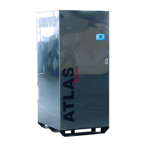
- Page 1 Copper-Fin Coil High Efficiency Condensing Boiler / Water Heater Models A050-A300 Operating and Maintenance Manual Designed and Manufactured in Accordance with ASME Code Section IV Heating Boilers E.T.L. Listed E.T.L. Canadian Listed U.L. 795 CSA 3.1 Photo shown may vary from actual model.
-
Page 2: Table Of Contents
Table of Contents Description Page # 1 Introduction ................................8 1-1 Pre-Installation ............................. 9 1-2 Boiler Nameplate and Model Number ....................... 10 1-3 Rating and Certifications ..........................11 1-4 Connection Information ..........................11 1-5 General Safety ............................11 2 Installation................................13 2-1 Installation Codes ............................ - Page 3 3-6 Diagnostic Mode ............................41 3-7 Error Mode ..............................42 3-8 Honeywell Sola Controller Start Sequence ....................43 3-9 Start/Stop Levels ............................44 3-10 High Limit Setpoint ..........................44 4 Enhanced/System Operator Interface Panel Operating Procedures ..............45 4-1 Introduction ..............................45 4-2 Enhanced Panel And System Operator Interface Panel Description ............
- Page 4 5-1.5 To Change CH Loop Time Of Day Setpoint ..................69 5-1.6 To Change CH Loop Off Hysteresis ....................69 5-1.7 To Change CH Loop On Hysteresis ....................69 5-1.8 To Change CH Loop Hysteresis Step Time ..................70 5-1.9 To Enable Or Disable CH Loop Outdoor Reset .................. 70 5-1.10 To Change CH loop P-I-D parameters ....................
- Page 5 5-6.1 To Enable Or Disable DHW High Limit ..................... 76 5-6.2 To Change DHW High Limit Setpoint ....................77 5-6.3 To Change Outlet High Limit Setpoint ....................77 5-6.4 To Change DHW High Limit Response ....................77 5-7 Stack Limit Related Configuration ......................77 5-7.1 To Enable Or Disable Stack Limit ......................
- Page 6 5-14.1 To Enable Lead Lag Master ......................82 5-14.2 To Change Lead Lag CH Setpoint..................... 82 5-14.3 To Change Lead Lag CH TOD Setpoint ................... 82 5-14.4 To Change Modbus Port ........................82 5-15 Lead Lag Advanced Setting: Modulation Parameter ................82 5-15.1 To Change Lead Lag Modulation Backup Sensor ................
- Page 7 5-24.4 To Change Burner Name ........................87 5-24.5 To Change Installation Data ......................87 5-24.6 To Change Temperature Units ......................87 5-24.7 To Turn On And Off The Unit Using Burner Switch ................ 88 5-24.8 To Enable Pump Test ........................88 5-24.9 To Enable Modulation Test .......................
-
Page 8: Introduction
Please review this manual carefully before installation or operation. A copy of this manual should be kept with the boiler at all times for reference. If this manual is misplaced or lost, check the Ace Heating Solutions, LLC. -
Page 9: Pre-Installation
Goods returned to the factory without an authorized Return Goods Authorization number will not be accepted. Ace Heating Solutions, LLC. is not responsible for any damage that the unit receives while in shipping. As each shipping company has its own procedure for filing a claim, please contact the shipper for claim instructions. -
Page 10: Boiler Nameplate And Model Number
1-2 Boiler Nameplate and Model Number The Boiler Name Plate The following illustration is an accurate depiction of the nameplate found on the rear side of the boiler. You will also find an ASME nameplate on the inlet pipe with some of the same information. A. -
Page 11: Rating And Certifications
(No Suffix refers to Indoor Jacketing) 1-3 Rating and Certifications All units must be installed in accordance with all state and local codes, and national codes, including but not limited to: ANSI Z21.10.2, Gas Water Boilers ANSI Z223.1/ NFPA 54, National Fuel Code ANSI/ NFPA 70, National Electric Code Atlas and Ace Boilers are National Board approved and designed–certified and tested by Intertek (E.T.L.), standards for the US and Canada (Can Std 1-3.1), and UL 795. - Page 12 and severe burns or death from scalds. When supplying general purpose domestic hot water, the recommended setting for the Operating control is 125 degrees F. Safety and energy conservation are factors to consider when setting the temperature aquastat on the unit. The most energy–efficient operation will result when the temperature setting is the lowest that satisfies the needs of the application.
-
Page 13: Installation
2 Installation 2-1 Installation Codes Installations must follow these codes: Local, state, provincial, and national codes, laws, regulations and ordinances National Fuel Gas Code, ANSI Z223.1/ NFPA 54 – latest edition (NFGC) National Electrical Code, ANSI/ NFPA 70 – latest edition (NEC) Standards for Controls and Safety Devices for Automatically Fired Boilers, ANSI/ASME CSD–1, (CSD–1) when required. -
Page 14: Combustion And Ventilation Air
must allow sufficient space behind the boiler to service vent connections, water pipe connections, piping and other auxiliary equipment, as well as the appliance. MODEL FRONT SIDE BOTTOM CLEARANCE CLEARANCE CLEARANCE CLEARANCE A050 18" 36" 6" 0" A075 18" 36" 6"... - Page 15 Provisions for combustion and ventilation air must be in accordance with Air for Combustion and Ventilation, of the latest edition of the National Fuel Gas Code, ANSI Z223.1, in Canada the latest edition of CGA Standard B149 Installation Code for Gas Burning Appliances and Equipment, or applicable provisions of the local building codes. In order to protect electrical components, the boiler room ambient air temperature shall not exceed 100 F.
-
Page 16: Conventional Combustion Air Supply
2. The exhaust vent must be installed with a slight upward slope of not more than ¼ inch per foot of horizontal run to vent terminal. 3. The exhaust vent must be insulated through the length of the horizontal run. 4. -
Page 17: Conventional Exhaust Venting
3. The opening must have a minimum free area of 1 sq. in. per 3,000 BTUH of the total input rating of all equipment in the room, or no less than the sum of the areas of all vent connectors in the confined space. (For additional information, referred to the latest NFGC) Warning: Do not use the “one permanent opening”... - Page 18 Note: Your Atlas Series Condensing Boiler requires Category IV venting. (See NFGC, NFPA 54, Section 7 “Venting Equipment” for more detailed information). The Atlas is designed to operate with a chamber pressure of 0 to +0.5" w.c. The Atlas Condensing boiler is capable of 100 feet of vertical equivalent exhaust when equipped with the standard exhaust vent.
- Page 19 US Installations Refer to the latest edition of the National Fuel Gas Code. 1. Vent must terminate at least 4ft below, 4 ft horizontally from or 1 ft above any door, window or gravity air inlet to the building. 2. The vent must not be less than 7ft above grade when located adjacent to public walkways. 3.
-
Page 20: Gas Supply
Vertical Venting (Category IV) The maximum and minimum venting length for this Category IV appliance shall be determined per the NFGC (US) or CGA, B149 (Canada). The diameter of the vent flue pipe should be sized according to NFGC (US) and Appendix B of the CGA, B149 (Canada). The minimum flue diameter for conventional venting using Category IV, stainless steel AL29-4C vent is: 6 inches for Models A050 –... - Page 21 Figure 2.4. Suggested Single Fuel Atlas Gas Piping Figure 2.5. Suggested Dual Fuel Atlas Gas Piping Rev 2.1...
-
Page 22: Pump Installation
Testing Gas Line Caution: The boiler must be disconnected from the gas supply during any pressure testing of the gas supply at test pressures in excess of ½ psi (14" w.c.). WARNING: The boiler must be isolated from the gas supply piping system by closing the upstream manual shut – off valve during any pressure testing of the gas supply system at test pressures equal to or more than ½... -
Page 23: Electrical Connections
In Canada, CSA C22.1 C.E.C. Part 1. The Atlas A050 – A100 boilers are wired for 120 VAC, 10 amps, while models A150 – A300 are wired for 120 VAC, 15 amps, although the units current will usually be much lower. Before starting the boiler, check to ensure proper voltage is supplied to the boiler and pump (if supplied). - Page 24 Check the Power Source Warning: Using a multi–meter, check the following voltages at the circuit breaker panel prior to connecting any equipment. Make sure proper polarity is followed and house ground is proved. (See below) AC = 108 VAC Minimum, 132 VAC Max; AB = 108 VAC Minimum, 132 VAC Max; BC = <1 VAC Max Figure 2.7.
-
Page 25: Dhw/Ch Installation And Programming
2-10 DHW/CH Installation and Programming Your Atlas Boiler is preprogrammed from the factory for Domestic Hot Water or Central Heating Application. Three different panel options are available: Basic Panel, Enhanced Panel, System Operator Interface Panel (reference pictures below). Installation and settings vary depending on the two programming modes and the display panel chosen. -
Page 26: 2-10.3 4-20 Ma Remote Setpoint
2-10.3 4–20 mA Remote Setpoint Remote setpoint control will be enabled from the factory with default setting of 40 F for 4 mA and 200 F for 20 mA. When the remote signal is connected to the boiler, setpoint is provided using the linear interpolation of the 4 mA and 20 mA input signal from the building automation controller. -
Page 27: 2-12.3 Add Stage Method
the slave’s commanded firing rate. If at least one stage has been dropped, no stage is requested to exceed the Common Base Load Rate. 2-12.3 Add Stage Method Factory default setting for adding a stage is Error Threshold method. A stage is added when the error becomes excessive based on the degrees away from setpoint and time. - Page 28 Rev 2.1...
-
Page 29: 2-13.2 Modbus Address Programming
2-13.2 Modbus Address Programming Each boiler on the daisy chain network must have a unique address. Go to Section 3 for instructions to change modbus address using Basic Panel or Section 4 with Enhanced display or System integrator display. 2-13.3 Lead Lag Bus Wiring Lead lag system function is communicated on the dedicated MB2 RS-485 bus on each boiler (MB2 A, B and C Terminals on Honeywell Controller) from the lead lag master to the slaves. -
Page 30: Suggested Piping
2-14 Suggested Piping 2-14.1 Suggested Domestic Hot Water Piping Diagrams Figure 2.9. Atlas in Primary Loop Piping Diagram Rev 2.1... - Page 31 Figure 2.10. One Atlas One Tank Suggest Piping Diagram Rev 2.1...
- Page 32 Figure 2.11. One Atlas Two Tank Piping Diagram Rev 2.1...
- Page 33 Figure 2.12. Two Atlas One Tank Piping Diagram Rev 2.1...
- Page 34 Figure 2.13. Two Atlas Two Tank Piping Diagram Rev 2.1...
-
Page 35: 2-14.2 Suggested Central Heating Piping Diagrams
2-14.2 Suggested Central Heating Piping Diagrams Figure 2.14. Atlas Primary Secondary Loop Piping Diagram Rev 2.1... - Page 36 Figure 2.15. Two Atlas in Primary Secondary Loop Piping Diagram Rev 2.1...
-
Page 37: Basic Panel Operating Procedures
3 Basic Panel Operating Procedures 3-1 Introduction The information in this Chapter provides a guide to the operation of the boiler using the Basic Panel mounted on the front of the unit. It is imperative that the initial startup of this unit be performed by factory trained personnel. Operation prior to initial startup by factory trained personnel will void the equipment warranty. -
Page 38: User Mode
3-4 User Mode In User Mode, the Basic Panel displays operating data of the unit such as Outlet temperature, CH setpoint, or boiler firing rate. The user can change screens by pressing the Next button. Depending on unit’s mode of operation, the Basic Panel distinguishes between two home screens: If CH call for heat is active, the Basic Panel considers Outlet temperature to be the home screen. -
Page 39: Setup Mode
Symbol Value Description Outlet Outlet Temperature or Outlet Display current outlet temperature and display Setpoint and modify current Outlet (CH) setpoint temperature Inlet Inlet Temperature Display current inlet temperature ¨ T Delta Temperature Display delta T temperature [outlet] - [inlet] DHW Temperature or DHW Display current DHW temperature and Display Setpoint... - Page 40 Setup Mode consists of the following items in Table 3.2. Pressing the Next button progresses through the Setup Mode screens. Symbol Value Description °F/°C Temperature Unit Set display to either degrees Fahrenheit or degrees Celsius. LBTHODLOD Outdoor Reset Parameter Display and modify Outdoor Reset feature ON or OFF.
-
Page 41: Diagnostic Mode
Lead Lag Configuration Lead lag configuration parameter can be changed in the Setup Mode. Enter Setup Mode and continue scrolling until Remote Firing Control screen is reached. The following parameters are mapped to Modbus addresses screen. LL - Lead Lag Operation Ldr: Master and slave enabled SLA: Slave only enabled OFF: Master and slave disabled... -
Page 42: Error Mode
Symbol Value Description Flame Signal Display current flame signal strength value in VDC. Alert Alert Display last Alert code number (See Appendix A for description). Lockout Lockout Display last Lockout code number (See Appendix B for description). Outlet Outlet Temp High Limit Display current outlet temperature high limit setting. -
Page 43: Honeywell Sola Controller Start Sequence
Lockout A Lockout code is displayed in the numerical part of the display when a Lockout state is received. When the Reset button is pressed, the Honeywell Sola Controller is forced to leave the Lockout state. Communication Timeout Alert code 981 is displayed as Basic Panel internal Alert when the Honeywell Sola Controller repeatedly does not respond to message queries sent by the Basic Panel. -
Page 44: Start/Stop Levels
Pump contact stays closed for 1 minute (configurable through Enhanced or System Operator Interface Panel) for boiler circulation pump to remove residual heat from heat exchanger. 3-9 Start/Stop Levels Start/Stop levels are controlled by setpoint, On and Off Hysteresis. Central Heating and DHW have its own setpoint, On Off Hystersis. -
Page 45: Enhanced/System Operator Interface Panel Operating Procedures
4 Enhanced/System Operator Interface Panel Operating Procedures 4-1 Introduction The information in this Chapter provides a guide to the operation of the boiler using the Enhanced Panel or System Operator Interface Panel. It is imperative that the initial startup of this unit be performed by factory trained personnel. Operation prior to initial startup by factory trained personnel will void the equipment warranty. -
Page 46: System Operator Interface Panel Home Page
4-4 System Operator Interface Panel Home Page For System Operator Interface multiple unit applications, each boilers is represented on the Home page by an icon and name. Pressing the icon allows the user to zoom in on that boiler and see specific details about it. These details are provided on a new page, which can include additional buttons that display additional detail and operation information, which itself leads to other pages. -
Page 47: Status Page
Figure 4.4 – Keyboard 4-7 Status Page A Status Page as in Figure 4.5 is displayed when a single boiler is selected on the Home Page or root page for equipment with Enhanced Panel. The Status Page displays the current condition of the unit and displays some of the more important configuration settings. -
Page 48: Configuration Password
Configuration parameters for the Honeywell Sola Controller (Flame Safe Guard and Operating Control) on any boiler connected in the Global Modbus™ network can be accessed from the System Operator Interface. Press the icon of the Honeywell Sola Controller on the Home Page to access the Status Page of each unit. Pressing the Configure button on the Status Page starts a configuration session of the Honeywell Sola Controller. -
Page 49: Change Parameter Settings
Figure 4.8 – Login Request The Honeywell Sola Controller on each boiler also maintains a password time out that limits the scope of the password entry. Once a password is successfully entered the unit starts an internal timer that expires after 10 minutes of inactivity. After the timer expires, the user is required to re-enter a password before a parameter can be changed. - Page 50 Figure 4.10 – Changing Configuration Parameter Page For safety configuration parameters an additional verification step is required to commit the changes. Safety parameters are grouped into blocks that include only safety parameters, not a mixture of safety data and non-safety data. All parameters within the safety group undergo a verification process.
-
Page 51: Fault/Alarm Handling
The settings of all parameters in each safety block must be confirmed to commit them in the Honeywell Sola Controller. When the user is done changing safety parameters, pressing the Confirm button begins the confirmation stage. The settings for all safety parameters in each changed block are presented and confirmed by the user as in Figure 4.13. Figure 4.13 –... -
Page 52: History Page
A less serious alarm condition may also occur that is treated as warning instead of a fault. Active fault codes for each annunciation and a warning code can be reported by each Honeywell Sola Controller. Any new fault code detected in a Honeywell Sola Controller is indicated as a lockout condition at the Operator Interface Display. -
Page 53: Operation Page
Figure 4.17 – Honeywell Sola Controller Alert Log 4-13 Operation Page The Operation Page displays the boiler running operation, including setpoint and firing rate. From this page the user can change setpoints, view annunciation information, and switch between Central Heating or Domestic Hot Water loops, as shown in Figure 4.20. -
Page 54: Trend Analysis Page
4-15 Trend Analysis Page Trend analysis of boiler status data can be viewed on the Operator Interface. A graph displays a historical view of Honeywell Sola Controller status data over varying time periods. A 2-dimensional graph with status data values shown on the Y axis over time specified on the X axis is displayed. Status for the most recent time is represented on the left side of the graph with older status running towards the right side of the graph. -
Page 55: Central Heating Parameters
Table 4.4 – Honeywell Sola Controller Identification Information 4-18 Central Heating Parameters Table 4.5 displays Central Heat configuration parameters. Refer to 5-1 CENTRAL HEAT RELATED CONFIGURATION for Central Heat parameter programming. Parameter Comment Password CH enable Disable or Enable Central Heating Loop None CH demand source Source for Central Heat demand... -
Page 56: Dhw Configuration Parameters
Maximum off point 32 °F to 240 °F (0 °C to 115 °C) None Table 4.6 – Outdoor Reset Configuration Parameters 4-20 DHW Configuration Parameters Table 4.7 displays Domestic Hot Water (DHW) configuration parameters. Refer to 5-3 DOMESTIC HOT WATER RELATED CONFIGURATION for Domestic Hot Water (DHW) parameter programming. -
Page 57: Modulation Configuration Parameters
Table 4.7 – Domestic Hot Water (DHW) Configuration Parameters 4-21 Modulation Configuration Parameters Table 4.8 displays Modulation configuration parameters. Refer to 5-4 MODULATION RELATED CONFIGURATION for Modulation parameter programming. Parameter Comment Password CH maximum modulation rate Installer These parameters provide the limits of fan speed during modulation. -
Page 58: Statistics Configuration Parameters
Parameter Comment Password CH pump control Auto or On CH pump operation Installer The CH pump can be turned on manually, or it can be set to operate automatically. If it is turned on, it remains on until changed back to Auto. In Auto mode it operates according to the demand sources listed for CH Pump Output and the overrun time. -
Page 59: Stack Limit Configuration Parameters
then a response defined by DHW high limit response will occur. Outlet high limit response Lockout Read only Outlet high limit setpoint 32 °F to 240 °F (0 °C to 115 °C) Installer Table 4.11 – High Limit Configuration Parameters 4-25 Stack Limit Configuration Parameters Table 4.12 displays Stack Limit configuration parameters. -
Page 60: Frost Protection Configuration Parameters
alert and holds while waiting for a delay to expire, and after the delay it tries again. Recycle & delay with limit: Same as above but with retry limit. If limit count is reached lockout will occur. Table 4.13 – Other Limit Configuration Parameters 4-27 Frost Protection Configuration Parameters Table 4.14 displays Frost Protection configuration parameters. -
Page 61: T-Rise Limit Configuration Parameters
Table 4.16 – Warm Weather Shutdown Configuration Parameters. 4-30 T-Rise Limit Configuration Parameters Table 4.17 displays T-Rise Limit configuration parameters. Refer to 5-12 T-RISE LIMIT CONFIGURATION for T-Rise Limit parameter programming. Parameter Comment Password Outlet T-rise enable Disabled or enable T-rise limit. Installer T-rise degrees If the T-rise limit is active and the outlet temperature... -
Page 62: Lead Lag Master Configuration Parameters
Table 4.18 – Lead Lag Slave Configuration Parameters 4-32 Lead Lag Master Configuration Parameters Table 4.19 displays Lead Lag Master configuration parameters. Refer to 5-14 LEAD LAG MASTER CONFIGURATION for Lead Lag Master parameter programming. Parameter Comment Password Master enabled Disabled: The master function is disabled. - Page 63 20 mA water temperature -40 to 266F (-40 to 130C) Installer This parameter provides the temperature for the interpolation of 4-20mA curve. This value determines the maximum possible value for the setpoint. Outdoor reset Enable or disable Installer This parameter enables or disables the lead lag master outdoor reset operation.
-
Page 64: Monitoring
value to be used instead. Some rate allocation algorithms may specify the use of this parameter, and that the slave base load setting are ignored. Table 4.26 – Lead Lag Advanced Setting: Rate Allocation Parameters Parameter Comment Password Method Error threshold: A stage is added when the error Installer becomes excessive based on degrees away from setpoint and time. -
Page 65: Trend Analysis Page
Figure 4.40 – Honeywell Sola Controller Detail Status Page Status information on the Detail Status Page is organized into groups and displayed on the page one group at a time. The user moves from one group to another using the Left and Right arrow buttons. Status data on the Detail Status Page is displayed in a menu for the group that is currently displayed. -
Page 66: Honeywell Sola Controller Diagnostics
Each status variable displayed in the trend analysis is represented by a different colored line, as follows: First status variable: Green Second status variable: Yellow Third status variable: Red Fourth status variable: Blue No more than two different measurement units (such as degrees), are allowed for the status variables selected in the trend analysis graph. -
Page 67: Installer Checkouts - Diagnostics Tests
Firing rate Fan speed Flame signal Header temperature If enabled Outlet temperature Degrees Inlet temperature If enabled DHW temperature If enabled Stack temperature If enabled Outdoor temperature If enabled Table 4.33 – Analog I/O Data Analog I/O data is displayed as bar charts depicting the I/O level. Analog I/O that is not enabled for the installation displays a blank I/O level. - Page 68 Edit the date and time and press the OK button to set the new settings. Press the Cancel button to exit without changing the time or date. Rev 2.1...
-
Page 69: Installer Integration Guide
5 Installer Integration Guide 5-1 Central Heat Related Configuration 5-1.1 To Enable or Disable CH Loop Configure CH – Central Heat Configuration Central Heat CH Enable Textbox (CH Mode Default: Enable, Remote Mod Default: Enabled, DHW Mode Default: Enabled, Com Mode Default: Enabled) Select Enable to enable CH loop Select Disable to disable CH loop This parameter determines whether the CH loop is enabled or disabled. -
Page 70: To Change Ch Loop Hysteresis Step Time
Configure CH – Central Heat Configuration Setpoint On Hysteresis Textbox (Default: 7 F) Type in desired temperature between 2 F and 30 F (1 C and 16 C) The on hysteresis is subtracted from the Setpoint to determine the temperature at which demand turns on. 5-1.8 To Change CH Loop Hysteresis Step Time Configure CH –... -
Page 71: To Change Ch Loop Setpoint Source
Configure CH – Central Heat Configuration Modulation I-Gain Textbox (Default: 50) Configure CH – Central Heat Configuration Modulation D-Gain Textbox (Default: 0) Type in desired number between 0 to 400 P gain applied to the proportional term of the PID equation for the CH loop. I gain applied to the Integral term of the PID equation for the CH loop. -
Page 72: To Change Low Water Temperature
If outdoor reset feature is enabled and the sensor is functioning properly, then the current outdoor temperature is used to determine the setpoint by interpolation. This lookup function uses two X and Y points to determine a line on the graph as shown in below. -
Page 73: To Change Dhw Loop Priority Versus Ch Loop
Select Sensor only for DHW demand from selected DHW modulation sensor Select DHW (S6) Switch for DHW demand from DHW switch (switch replaces the DHW sensor) When sensor input is shorted burner demand exist outlet sensor will provide the temperature control Select STAT Terminal for DHW demand from STAT input Select Auto DHW (S6) or sensor only for DHW demand from DHW switch and DHW sensor 5-3.3 To Change DHW Loop Priority Versus CH Loop... -
Page 74: To Change Dhw Loop P-I-D Parameters
5-3.10 To Change DHW Loop P-I-D Parameters Configure DHW – Domestic Hot Water Configuration P-Gain Textbox (Default: 50) Configure DHW – Domestic Hot Water Configuration I-Gain Textbox (Default: 50) Configure DHW – Domestic Hot Water Configuration D-Gain Textbox (Default: 0) Type in desired number between 0 to 400 P gain applied to the proportional term of the PID equation for the DHW loop. -
Page 75: To Change Dhw Loop Forced Rate Time
5-4.5 To Change DHW Loop Forced Rate Time Configure Modulation Configuration DHW Forced Rate Time Textbox (Default: 0m10s) Type in desired time between 0 to 5 minutes For DHW demand, if the DHW forced rate time is non-zero, then the firing rate will be held at the rate specified here during that time. -
Page 76: To Set Dhw Loop Pump Control On Or Auto
This time indicates how long the CH pump should remain on after demand from any source ends. That is, whenever the pump has been on, but the last requests for the pump to be on ends, it always continues to run for the time given by this parameter. -
Page 77: To Change Dhw High Limit Setpoint
Select Disable to disable DHW loop high limit This parameter enables or disables the DHW high limit function. It must be disabled when the DHW input is used as a switch to indicate DHW demand. 5-6.2 To Change DHW High Limit Setpoint Configure High Limits DHW High Limit Setpoint Textbox (Default: 200 F) -
Page 78: Delta-T Limit Related Configuration
5-8 Delta-T Limit Related Configuration 5-8.1 To Enable Or Disable Delta-T Limit Configure Delta T Inlet to Outlet Flow Delta-T Enable Textbox (Default: No Delta-T) Select Enable to enable Delta-T limit Select Disable to disable Delta-T limit This parameter enables or disables the entire delta-T limit function. 5-8.2 To Change Delta-T Limit Delay Configure Delta T... -
Page 79: Frost Protection Related Configuration
Select Recycle & delay with retry limit to recycle and delay in event of Delta-T inverse limit up to Delta-T retry limit 5-9 Frost Protection Related Configuration 5-9.1 To Enable Or Disable CH Loop Frost Protection Configure Frost Protection Configuration CH Frost Protection Enable Textbox (Default: Disabled) Select Enable to enable CH loop frost protection... -
Page 80: Dhw Storage Configuration
(Default: 5m0s) Type in desired time between 0 to 5 minutes This time indicates how long the DHW pump should remain on after frost protection demand ends. That is, whenever the pump has been on due to frost protection and then this demand ends, it always continues to run for the time given by this parameter. -
Page 81: To Change T-Rise Degree
Select Enable to enable Outlet T-rise Select Disable to disable Outlet T-rise 5-12.2 To Change T-Rise Degree Configure T-Rise Limit Configuration T-rise Degree Textbox (Default: 50 F/sec) Type in desired outlet T-rise degree If the outlet temperature rises faster than this number of degrees per minute, then the T-rise response will occur. 5-12.3 To Change T-Rise Response Configure T-Rise Limit Configuration... -
Page 82: To Change Demand To Firing Delay
5-13.5 To Change Demand To Firing Delay Configure Lead Lag Slave Configuration Demand to Firing Delay Textbox (Default: 2m0s) Type in desired slave demand to firing delay Length of time to wait between requesting a stage to fire and detecting that it has failed to start. 5-13.6 To Change Modbus Port Configure Lead Lag Slave Configuration... -
Page 83: To Change Lead Lag On Hysteresis
Differential above setpoint when last LL stage boiler is turned off. 5-15.3 To Change Lead Lag On Hysteresis Configure Lead Lag Master Configuration Advanced Setting Modulation On Hysteresis Textbox (Default: 10 F) Type in desired LL on hysteresis Differential below setpoint when first LL stage boiler is turned on. 5-15.4 To Change Lead Lag Hysteresis Step Time Configure Lead Lag Master Configuration... -
Page 84: To Enable Or Disable Lead Lag Ch Loop Outdoor Reset
5-16.5 To Enable Or Disable Lead Lag CH Loop Outdoor Reset Configure Lead Lag Master Configuration Advanced Setting Central Heat Outdoor Reset Textbox (Default: Disabled) Select Enable to enable CH loop outdoor reset Select Disable to disable CH loop outdoor reset If outdoor reset is enabled then the current outdoor temperature is used to determine the Setpoint by interpolation using LL CH Setpoint (or LL CH Time-Of-Day Setpoint if TOD is on), the min water temperature, and the min and max outdoor temperatures. -
Page 85: Lead Lag Advanced Setting: Wwsd Parameter
This parameter represents the lead lag firing rate when frost protection is enabled. 5-19 Lead Lag Advanced Setting: WWSD Parameter 5-19.1 To Enable Or Disable Lead Lag WWSD Configure Lead Lag Master Configuration Advanced Setting WWSD Enable Textbox (Default: Disabled) Select Disable to disable WWSD Select Shutdown after demand ended to allow any current CH demand that is present prevents WWSD from becoming true... -
Page 86: Lead Lag Advanced Setting: Add Stage Parameter
Configure Lead Lag Master Configuration Advanced Setting Rate Allocation Base Load Common Textbox (Default: 40%) Type in desired rate % If this parameter is zero, this parameter is disabled. For any non zero value, individual base rate of each slave to be ignored by the LL master’s routines and this common value will be used instead. -
Page 87: 5-24.4 To Change Burner Name
Configure Lead Lag Master Configuration Advanced Setting Drop Stage Detection Time Textbox (Default: 0m30s) Type in desired time This parameter determines how long drop stage condition needs to persist for drop stage to occur. 5-23.3 To Change Drop Stage Error Threshold Configure Lead Lag Master Configuration Advanced Setting... -
Page 88: 5-24.7 To Turn On And Off The Unit Using Burner Switch
Configure System Configuration Temperature Units Textbox (Default: Fahrenheit) Select Fahrenheit to show temperature in Fahrenheit Select Celsius to show temperature in Celsius This parameter determines whether temperature is represented in units of Fahrenheit or Celsius degrees. 5-24.7 To Turn On And Off The Unit Using Burner Switch Operation Burner Switch Button (Default: Yes/True/On) This parameter enables or disables the burner control. -
Page 89: Start Up Instructions
This start-up fire test report must be filled out and a copy must be sent to Ace Heating Solutions, LLC in the pre-addressed envelope provided with the unit in order to register the unit for the warranty. -
Page 90: Verification
When unit is started up, it is important to check the following parameters and adjust them to the values seen on the factory test report. Please record the values in the blank spaces below. The values must be within the range seen below. Carbon Monoxide __________ ppm (must be kept below 100 ppm) Carbon Dioxide... -
Page 91: 6-4.2 Pilot Turndown Test - (Optional At Installation, Required Annually After)
6-4.2 Pilot Turndown Test - (Optional at Installation, Required Annually After) To test that the main burner can be lit by the smallest pilot flame the can be seen by the flame amplifier and energize the FLAME LED. Clean the flame detector to make sure that it detects the smallest acceptable pilot flame. This test should be performed annually. -
Page 92: 6-4.4 Gas Valve Leak Test
5) If the flame signal is higher than 0.5 Vdc and the flame LED does come on, contact your local Ace Heating Solutions, LLC. representative for more help. Site-glass Petcock White ceramic spark rod Gas ball-valve Figure 6.2. Atlas Combustion Assembly Without Figure 6.3. - Page 93 Figure 6.5 Vas Valve Diagram Figure 6.6 Test Setup Diagram *WARNING- REMOVE POWER FROM THE SYSTEM BEFORE BEGINNING THE VALVE LEAK TEST TO PREVENT ELECTRICAL SHOCK. 1) De-energize the control system to make sure no power goes to the valves. 2) Close the upstream manual gas cock 3) Make sure the manual test petcock (D) is closed in the leak test tap assembly 4) To test the first Safety shut off valve, remove the 1/8 in.
-
Page 94: 6-4.5 Safety Shutdown Tests (All Installations)
The gas train has been checked before shipping, but could come loose during shipping. Turn “OFF” all electric power and open the main gas valve. Turn the unit’s switch to the “ON” position and open the main gas valve and the ball valve to the burner mixer tube (the one between the fuel-air ratio valve and the venturi). -
Page 95: 6-4.6 Blocked Drain Test - (Optional)
6-4.6 Blocked Drain Test - (Optional) The blocked drain safety feature checks to make sure the drain does not have any blockage by ensuring the water level from the condensate does not exceed a specific level. This check is not necessary, but is recommended. To check if the safety device is operating properly: 1) Close off the end of the condensate pipe with a ½"... - Page 96 6. Enter Diagnostic Mode by pressing Next button on the Basic Panel for 3 seconds. Once in Diagnostic Mode and press Next button until Min icon is flashing and Diag icon is solid. Unit will now be running at 10% firing rate. 7.
-
Page 97: 6-5.2 Air Flow Switch Calibration
IN SOME EXTREME CONDITIONS, SUCH AS HIGH ALTITUDES OR LOW HEATING VALUE GAS, IT MAY NOT BE POSSIBLE TO FIRE AT THE RATED MAXIMUM WITH THE APPROPRIATE AMOUNT OF EXCESS AIR. IN THIS CASE, REDUCE THE HIGH-FIRING RATE UNTIL THE DESIRED EXCESS AIR HAS BEEN OBTAINED AT THE MAXIMUM FIRING RATE. -
Page 98: After Startup Checklist
• Set the burner cutoff switch on the display panel to the off position. • Wait for the unit to complete its postpurge. • Turn off the power supply to the unit via the user installed disconnect switch. • Close the unit’s main gas valve. WARNING FAILURE TO FOLLOW THE SHUT DOWN PROCEDURE WILL RESULT IN EXCESSIVE WEAR AND WILL VOID YOUR WARRANTY. -
Page 99: Maintenance
7 Maintenance Maintenance is an important part of keeping the Atlas boiler running efficiently and for a long period of time. Ace recommends that a maintenance schedule be kept. For extended warranty, schedule must be kept and made available to Ace if failure occurs. - Page 100 If combustion readings are not between recommended values, then adjustments should be made to the gas valve until all readings are within these recommended values. Carbon Monoxide __________ ppm (must be kept below 100 ppm) Carbon Dioxide __________ % (should be kept between 7-9%) Excess Air __________ % (should be kept between 30-45%) __________ ppm (should be kept under 15 ppm)
-
Page 101: Maintenance Schedule
7-2 Maintenance Schedule Atlas Model A Condensing Boiler Yearly Maintenance Schedule Notes Daily Observe Op Temp Observe Noise Check for Water Leak Check Lockout Codes Monthly Check Test Operating Control Pilot/Main Flame Sig Air Filter Condensate Drain System Observe Main Flame In each of the boxes write "P"... -
Page 102: Appendices
Appendices Appendix A - Troubleshooting And Hold/Lockout Code To support the recommended troubleshooting, the Honeywell Sola Controller has a History File. Review the alert history for possible trends that may have been occurring prior to the actual Lockout. Alert code and Hold/Lockout code can be accessed through Basic Panel, Enhanced or System Operator Interface Panel. For instruction on accessing Alert and Hold/Lockout code using Basic Panel display, refer to CHAPTER 3-6 DIAGNOSTIC MODE for more information. - Page 103 2. Check the Module power supply and make sure that frequency, voltage and VA meet the specifications. Modulation fault Internal sub-system fault. 1. Review alert messages for possible trends. Pump fault 2. Correct possible problems. Motor tachometer fault AC inputs phase reversed 1.
- Page 104 3. If previous steps are correct and fault persists, consult factory. Header sensor fault 1. Check wiring and correct any possible errors. 2. Replace the header sensor. 3. If previous steps are correct and fault persists, consult factory. Stack sensor fault 1.
- Page 105 2. If fault repeats, consult factory Combustion pressure ON 1. Check wiring and correct any errors. 2. Inspect the Combustion Pressure Switch to make sure it is Combustion Pressure Off working correctly. 3. Reset and sequence the relay module. 4. During STANDBY and PREPURGE, measure the voltage between J6 terminal 5 and L2 (N).
- Page 106 Invalid Pilot type setting Invalid Postpurge time setting Invalid Power up with lockout setting Invalid Pre-ignition time setting Invalid Prepurge rate setting Invalid Prepurge time setting Invalid Purge rate proving setting Invalid Run flame failure response Setting Invalid Run stabilization time setting Invalid Stack limit enable setting Invalid Stack limit response setting Unconfigured Delta T limit setpoint setting...
- Page 107 Alert Code Description Code Description None (No alert) Alert PCB was restored from factory defaults Safety configuration parameters were restored from factory defaults Configuration parameters were restored from factory defaults Invalid Factory Invisibility PCB was detected Invalid Factory Range PCB was detected Invalid range PCB record has been dropped EEPROM lockout history was initialized Switched application annunciation data blocks...
- Page 108 Modulation was overridden due to sensor fault Absolute max fan speed was out of range Absolute min fan speed was out of range Fan gain down was invalid Fan gain up was invalid Fan minimum duty cycle was invalid Fan pulses per revolution was invalid Fan PWM frequency was invalid Modulation output type was invalid Firing rate control parameter was invalid...
- Page 109 DHW sensor type was invalid Inlet sensor type was invalid for DHW Outlet sensor type was invalid for DHW DHW control was suspended due to fault DHW temperature was invalid DHW inlet temperature was invalid DHW outlet temperature was invalid Lead Lag P-gain was invalid Lead Lag I-gain was invalid Lead Lag D-gain was invalid...
- Page 110 Abnormal Recycle: Flame was lost during Run Abnormal Recycle: Leakage test failed Abnormal Recycle: Interrupted air flow switch was off during Drive to Purge Rate Abnormal Recycle: Interrupted air flow switch was off during Measured Purge Time Abnormal Recycle: Interrupted air flow switch was off during Drive to Light off Rate Abnormal Recycle: Interrupted air flow switch was off during Pre-Ignition test Abnormal Recycle: Interrupted air flow switch was off during Pre-Ignition time Abnormal Recycle: Interrupted air flow switch was off during Main Flame Establishing Period...
- Page 111 Abnormal Recycle: Check Parameters Failed Internal error: No factory parameters were detected in control Internal error: PID iteration frequency was invalid Internal error: Demand-Rate interval time was invalid Internal error: Factory calibration parameter for modulation was invalid Internal error: CH PID P-scaler was invalid Internal error: CH PID I-scaler was invalid Internal error: CH PID D-scaler was invalid Internal error: DHW PID P-scaler was invalid...
-
Page 112: Appendix B- Replacement Parts
Appendix B- Replacement Parts MODELS A050-A150 Description A050 A075 A100 A150 Heat Exchanger ATHX050 ATHX075 ATHX100 ATHX150 Water Flow switch PPFIS-1 PPFIS-1 PPFIS-1 PPFIS-1 Temp Sensor Well CHMANAQWL-1 CHMANAQWL-1 CHMANAQWL-1 CHMANAQWL-1 Outlet /Stack CAA50001464-007 CAA50001464-007 CAA50001464-007 CAA50001464-007 Temp Sensor Inlet/Outdoor/DHW/ CAA198799Z CAA198799Z CAA198799Z... - Page 113 Rev 2.1...
-
Page 114: Atlas Warranty
Claim for a warranty must be filled within 10 business days of when the failure occurs. This warranty cannot be extended for any reason except by Ace Heating Solutions, LLC and must be done in a written form. In order to make a warranty claim, a purchase order and national board number is required prior to any repairs or replacements being made. - Page 115 Extended Warranty: An extended 7-year heat exchanger warranty to the customer follows the same conditions as stated above and will be as follows: Year Discount 100% Summary of Atlas Acceptable Conditions (per O & M manual) Subjects Condition Min Velocity Minimum flow is based on both firing rate and inlet water temperatures.
- Page 116 Model No. www.aceheatingllc.com Ace Heating Solutions, LLC. All rights reserved. Printed in the USA Performance specifications are effective with date of issue and are subject to change without prior notice. The brand and product names contained within this document are trademarks or registered of their respective holders.
Need help?
Do you have a question about the Atlas A050 and is the answer not in the manual?
Questions and answers
Error code 108 flame out during run