Table of Contents
Advertisement
Quick Links
Advertisement
Table of Contents

Subscribe to Our Youtube Channel
Related Manuals for Extreme Flight Legacy Aviation Muscle Bipe


Summary of Contents for Extreme Flight Legacy Aviation Muscle Bipe
- Page 1 Legacy Aviation Muscle Bipe Assembly Manual Copyright 2019 Extreme Flight...
- Page 2 ALL liability for the use of this product, please return it to the place of purchase immediately. Extreme Flight RC, Ltd. guarantees this kit to be free of defects in materials and workmanship for a period of 30 DAYS from the date of purchase. All warranty claims must be accompanied by the original dated receipt.
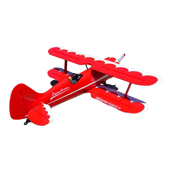
- Page 3 Congratulations on your purchase of the Legacy Aviation Muscle Bipe! Loosely based on the hot-rodded and highly modified Waco UPF-7 flown by the late airshow legend Jimmy Franklin and known as the Mystery Ship, the Muscle Bipe is our tribute to classic barnstormer airshow style aerobatics.
- Page 4 9. Thin CA, 30 minute epoxy, canopy glue/foam tac Recommended items to complete the Muscle Bipe 1. 4 MKS HV69 servos and Extreme Flight RC 25T lightweight 1.25” servo arms. 2. 2 Hitec 7245 servos and Extreme Flight RC 24T lightweight 1.25” servo arms.
-
Page 5: Wing Assembly
Let’s begin assembly of the Muscle Bipe (MB): Wing assembly 1.We will begin with the wings. There are 5 wing panels, 2 upper wing halves, 2 lower wing halves and a center upper wing section. Set the center upper wing half aside as we will not be using that till later. - Page 6 2. Locate the control horns for the ailerons, see figure 2. Be sure to lightly sand the portion that will insert into the precut slot as well as one side of the base plate. Now trial fit the control horn thru the base plate, trim the base plate slot if necessary to accommodate the control horn, then insert this into the slot (use any base plate they will fit any control horn).
- Page 7 3. Using your 4 micro servos (we recommend the MKS HV69 as seen in figure 4) we will now install these servos. Begin with the upper wings (they are shorter than the lower wings) and carefully pull the servo lead thru the wing and out of the wing root. Do this to the remaining upper wing half at this time.
-
Page 8: Landing Gear
insert nut is recommended on the bottom of the servo arm in any case. Make sure your servo moves the control surface in the correct direction and to the desired throw. If there is any binding fix it now, since we used CA hinges they generally do not bind, but if you have a stiff surface then unhook the pushrod and physically move the surface from bevel to bevel several times, this will loosen it up, repeat if necessary. - Page 9 Figure 6 TIP: we used blue painters tape to hold the cuffs in place, as well as using the tape to seal around the area where the rubber edging meets the fuselage and the gear to cuff area to prevent any glue from running out.
- Page 10 Figure 7 Figure 8...
-
Page 11: Tailwheel Assembly
Figure 9 Tailwheel assembly 5. Locate the tailwheel assembly and associated hardware, then review figure 10 for parts identification. We begin by mounting the tailwheel bracket mounting flat to the fuselage, trial fit first to be sure it is centered side to side then the pivot point of the bracket has to be centered to the rudder hinge line. - Page 12 Figure 10 Figure 11...
- Page 13 Center wing installation Locate the center wing section, 4 black struts and 3mm bolts/washers. The strut end that has two holes will go into the fuselage, the other end will attach to the wing. Begin by inserting the two hole end into the fuselage and install the bolts be sure to use blue thread lock. Do this to all 4 struts then mount the upper wing center section to those struts.
- Page 14 Figure 14...
-
Page 15: Tail Assembly
Tail assembly 6. Locate the horizontal stabilizer and elevator, separate the two pieces and keep track of your CA hinges. You will need to remove the small plug in the rudder hinge line to insert the stabilizer, as well we suggest mounting the 4 wing halves. Now take the horizontal stabilizer and dry fit it into the slot, take a look from the front and back of the plane to assure it is parallel to the wings. - Page 16 Figure 16 Figure 17...
- Page 17 Figure 18 Figure 19...
-
Page 18: Rudder Installation
Rudder installation 7. Next locate the rudder and we will begin hinging it to the vertical stabilizer. Using the same methods as before, I chose to insert the CA hinges into the vertical stabilizer then slide the rudder onto those hinges to complete the process. Locate that remaining tailwheel screw and insert it into the tiller arm then into the bottom of the rudder. - Page 19 Next install the servo arm, we used Extreme Flight RC 1.25” lightweight arms as shown in figure 19. With the control surface centered, trial fit the pushrod and see if it fits, if not turn the ball link on each end equal number of turns till the overall pushrod is of proper length.
- Page 20 Figure 23...
-
Page 21: Motor And Esc Installation
Figure 24 Motor and ESC installation If using the Torque 4016-500KV MKII motor from Extreme Flight, the installation is quite easy. The motor will need to have the X Mount and prop adapter installed, refer to the included instructions and figure below. The firewall is already spaced for this motor, simply locate the 4mm mounting bolts/washers and bolt the motor to the firewall, blind nuts are already installed so just apply some blue thread lock. - Page 22 Figure 25 Figure 26...
- Page 23 Figure 27 Figure 28...
- Page 24 Cowling 10. The top of the cowling has no bolts and is easily removable for access to the battery compartment. It is held in place with 2 magnets and hooks. Locate the radial engine piece and trial fit the piece into the bottom half of the cowling. Notice there are two notches in this piece and they fit to the upper portion of the cowling.
-
Page 25: Final Assembly
Figure 30 Final assembly 11. We will now fish two 18” servo extension wires from the upper wing center section into the fuselage. There are holes in the wing and fuselage to run these extensions, refer to figure 31 for our setup. - Page 26 Now choose a location to mount your receiver, we used the platform that is located just inside the removable hatch on the bottom of the fuselage. We also used an Aura flight control system (gyro) and mounted it on the aft portion of the battery tray. See figure 32. Figure 32 Any satellite receivers can be mounted to the fuselage sides.
- Page 27 Figure 33 Figure 34 We suggest a 16X7 propeller if using the Torque 4016 motor, it can now be mounted to the motor and using the supplied prop nut yields a nice overall look.
- Page 28 Setup/Throws Center of gravity: we balanced ours using the top wing as our reference. There are two holes where the wing bolts are located, the CG range is front of that hole to 1” behind the hole. Move the 6S fore/aft in the battery tray to the desired CG location. See figure 35 for locating the CG range and figure 36 for our battery location.
- Page 29 Landings are made by establishing a constant glide path and just before touch down slowly retard the throttle and touching down. Thanks again for your purchase of the Legacy Aviation Muscle Bipe! Jeff Williams Team Extreme...
Need help?
Do you have a question about the Legacy Aviation Muscle Bipe and is the answer not in the manual?
Questions and answers