Table of Contents
Advertisement
Quick Links
Advertisement
Table of Contents

Related Manuals for AEMC CM605


Summary of Contents for AEMC CM605
- Page 1 CM605 AC/DC LOW CURRENT CLAMP-ON METER E N G L I S H User Manual...
- Page 2 The recommended calibration interval for this instrument is 12 months and begins on the date of receipt by the customer. For recalibration, please use our calibration services. Refer to our repair and calibration section at www.aemc.com. Serial #: ________________________________ Catalog #: 7000.02 Model #:...
-
Page 3: Table Of Contents
Table of Contents 1. INTRODUCTION ................2 International Electrical Symbols ............3 Receiving Your Shipment ..............3 Ordering Information ................3 2. PRODUCT FEATURES ..............4 Control Features ..................4 Display Features ..................5 Button Functions ..................5 2.3.1 HOLD/PEAK Button ...............5 2.3.2 ZERO Button ................5 3. -
Page 4: Introduction
Do not perform resistance or continuity tests on a live circuit. • Use extreme care when working around bus bars and bare conduc- tors. • Do not use the meter in overrange/overload conditions (OL). • When the multimeter clamp is linked to the measurement circuits, do not touch any unused terminals. • Before changing the function, disconnect the measurement leads from the circuit measured. AC Clamp-on Meter Model CM605... -
Page 5: International Electrical Symbols
Do not use an instrument that appears to be damaged. 1.3 Ordering Information Model CM605 ..................Cat. #7000.02 Includes clamp-on meter, lead set (red & black lead) with needle point test probes, carrying case, 2x1.5V AAA batteries and a user manual. AC Clamp-on Meter Model CM605... -
Page 6: Product Features
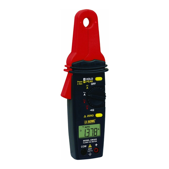
1. Tapered jaws for crowded wiring or areas (Ø.45"- 12mm) 2. Safety barrier anti-slip guard 3. Lever for jaw opening/closing 4. LCD display 5. COM (Black) and Positive (Red) input terminal jacks 6. Data hold and Peak hold buttons 7. Rotary range selector switch AC Clamp-on Meter Model CM605... -
Page 7: Display Features
ZERO Button • To activate, press the ZERO button to enter the Zero mode. • The symbol will appear and Zero the display. The reading is stored as a reference value for subsequent measure- ments. • To exit the Zero mode, press the ZERO button again. AC Clamp-on Meter Model CM605... -
Page 8: Specifications
40 to 500Hz Overload Protection: 660Vrms DC Volts ( ) - Positive only* Range Resolution Accuracy Input Impedance 600V 100mV 1.0% R ± 2cts 10MΩ Overload Protection: 660Vrms * For negative measurement, add 2cts to the accuracy AC Clamp-on Meter Model CM605... -
Page 9: Environmental Specifications
Low Battery Indicator: is displayed when the voltage supplied by the batteries is lower than the operat- ing voltage. Power Supply: 2 batteries - 1.5V type AAA (LR03) Auto-off: Automatic shut down after approx 10 minute with over-ride Sampling: Approx 2 measurements/second 3.2 Environmental Specifications Operating Temperature: 32° to 104°F (0° to 40°C), < 80% RH max non-condensing Storage Temperature: 14° to 140°F (-10° to 60°C), < 70% RH max non-condensing Altitude: 6000 ft (2000m) AC Clamp-on Meter Model CM605... -
Page 10: Mechanical Specifications
3.3 Mechanical Specifications Maximum Cable Diameter: Ø 0.45" (12mm) Maximum Jaw Opening: Ø 0.60" (15mm) Dimensions: 7.44 x 2.80 x 1.46" (189 x 71 x 37mm) Weight: 6.5 oz (180g) 3.4 Safety Specifications IEC/EN 61010-1, 600V CAT II, 300V CAT III Insulation: Class II Pollution Degree: 2 AC Clamp-on Meter Model CM605... -
Page 11: Operation
CAT III: CAT III circuits are high-power appliance power circuits, which may carry high-level transient over-voltage. Example: industrial machinery or instrument power supplies For your own safety, only use factory supplied leads and always check that they are in perfect working order. AC Clamp-on Meter Model CM605... -
Page 12: Ac Current Measurement
4.2 AC Current Measurement • Turn the switch to the range. • Remove the test leads before measuring current . • Clamp the jaws around the conductor to be measured. • Take the current reading after it stabilizes. WARNING: Immediately remove the test probes from the circuit under test if overload “OL” is displayed. CORRECT INCORRECT (two conductors from different phases) AC Clamp-on Meter Model CM605... -
Page 13: Dc Current Measurement
• Press the lever to open the jaws. • Clamp the jaws around the conductor to be measured. • If reading is unstable and is hard to read, push the HOLD button and read the measurement. WARNING: Immediately unclamp the meter from the conductor under test if overload " " is displayed. AC Clamp-on Meter Model CM605... -
Page 14: Ac Voltage Measurement
4.4 AC Voltage Measurement Automatic measurement range: 600V AC/DC • Turn the switch to the range. • Insert the red lead to the red “+” input jack and the black lead to the black "COM" input jack. • Bring the test probe tips into contact with the test points. • Take the voltage reading after it stabilizes. WARNING: Immediately remove the test probes from the circuit under test if overload “OL” is displayed. AC Clamp-on Meter Model CM605... -
Page 15: Dc Voltage Measurement
4.5 DC Voltage Measurement Automatic measurement range: 600V AC/DC • Turn the switch to the range. • Insert the red lead to the red “+” input jack and the black lead to the black "COM" input jack. • Take the voltage reading after it stabilizes. WARNING: Immediately remove the test probes from the circuit under test if overload “OL” is displayed. AC Clamp-on Meter Model CM605... -
Page 16: Resistance Measurement
(dead circuit). It is also important that all capacitors in the measured circuit be fully discharged. • Turn the rotary switch to the range. • Insert the red lead to the red “+” input jack and the black lead to the black "COM" input jack. • Bring the test probe tips into contact with the sample under test. WARNING: If overload “OL” is displayed, the resistance exceeds the measurement range or the circuit is open. AC Clamp-on Meter Model CM605... -
Page 17: Continuity Test
WARNING: When testing continuity, make sure that the power is off (dead circuit). • Turn the rotary switch to the range.. • Insert the red lead to the red “+” input jack and the black lead to the black "COM" input jack. • Bring the test probe tips into contact with the sample under test. • The buzzer sounds when the circuit to be checked is DC or has a resis- tance of less than 100Ω ± 25Ω. WARNING: If overload "OL" is displayed, the continuity exceeds the measurement range or the circuit is open. AC Clamp-on Meter Model CM605... -
Page 18: Analog Output
"COM" input jack. • Connect the ends of both cables to an oscilloscope or another multimeter. • Clamp the jaws around the conductor to be measured. • Read the analog signal on the oscilloscope or multimeter. - If the signal measured is continuous, the output signal will be DC. - If the signal measured is alternating, the output signal will be AC. AC Clamp-on Meter Model CM605... -
Page 19: Maintenance
5.2 Battery Replacement • The batteries will need to be replaced when the symbol appears on the display. • The meter must be in the OFF position and disconnected from any circuit or input. • Remove the battery cover screws with a screwdriver. • Replace the old batteries with two new 1.5V AAA (LR03) batteries. • Replace the battery compartment cover and tighten the screws. 5.3 Cleaning • To clean the instrument, wipe the case with a damp cloth and mild detergent. Do not use abrasives or solvents. • Do not get water inside the case. This may lead to electrical shock or damage to the instrument. AC Clamp-on Meter Model CM605... -
Page 20: Repair And Calibration
NOTE: You must obtain a CSA# before returning any instrument. Technical and Sales Assistance If you are experiencing any technical problems, or require any assistance with the proper operation or application of your instrument, please call, mail, fax or e-mail our technical support team: AEMC Instruments ® 200 Foxborough Boulevard Foxborough, MA 02035 USA Phone: (800) 343-1391 (508) 698-2115 Fax: (508) 698-2118 techsupport@aemc.com www.aemc.com NOTE: Do not ship Instruments to our Foxborough, MA address. AC Clamp-on Meter Model CM605... -
Page 21: Limited Warranty
® If a malfunction occurs within the one-year period, you may return the instrument to us for repair, provided you submit a proof of purchase. AEMC ® will, at its option, repair or replace the faulty material. Warranty Repairs... - Page 22 Notes: AC Clamp-on Meter Model CM605...
- Page 24 11/09 99-MAN 100346 v1 Chauvin Arnoux , Inc. d.b.a. AEMC Instruments ® ® 15 Faraday Drive • Dover, NH 03820 USA • Phone: (603) 749-6434 • Fax: (603) 742-2346 www.aemc.com...
Need help?
Do you have a question about the CM605 and is the answer not in the manual?
Questions and answers