
Related Manuals for Digisol DG-GS4526P


Summary of Contents for Digisol DG-GS4526P
- Page 1 DG-GS4526P 22 PORT 10/100/1000MBPS LAYER 2 POE SWITCH WITH 4 GC PORTS Installation Guide V1.2 2013-07-01 As our products undergo continuous development the specifications are subject to change without prior notice...
-
Page 2: Table Of Contents
DG-GS4526P Installation Guide Content Content CHAPTER 1 INTRODUCTION............3 1.1 P ..................3 RODUCT RIEF 1.1.1 Overview....................3 1.1.2 Features and Benefits ................3 1.2 P ..............4 HYSICAL PECIFICATIONS 1.3 D ..............5 ESCRIPTION OF ARDWARE 1.3.1 Front Panel ....................5 1.3.2 Back Panel....................5 1.3.3 Status LEDs.................... -
Page 3: Chapter 1 Introduction
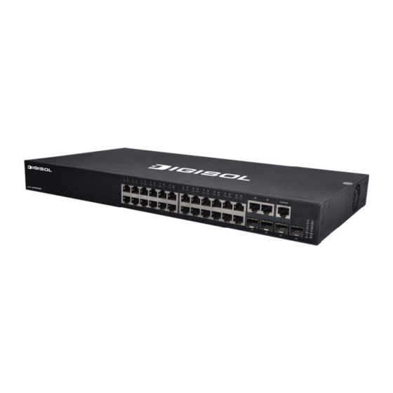
DG-GS4526P Installation Guide Chapter 1 Introduction 1.1 Product Brief DG-GS4526P: Fig 1-1 DG-GS4526P Switch 1.1.1 Overview DG-GS4526Pseries switch with advanced intelligent and secure features, can serve ideally as distribution layer switches for the 1000Mb input device of campus networks, enterprise networks and IP metropolitan networks. -
Page 4: Physical Specifications
DG-GS4526P Installation Guide QoS DG-GS4526P series switch fully support DiffServ Module. Users can specify a queue bandwidth each port. WRR/SP/SWRR scheduling also supported. DG-GS4526Pseries support the port security. Users can deploy trusted CoS, DSCP, IP precedence and port priority. User can also modify packets’ DSCP and COS values. The traffic can be classified by port, VLAN, DSCP, IP precedence and ACL table. -
Page 5: Description Of Hardware
Min. 80, 000 Hours MTBF 1.3 Description of Hardware 1.3.1 Front Panel DG-GS4526P has 22 10/100/1000Base-T ports, 4 Combo ports (4 RJ-45 and 4 SFP), 1 Console port and 32 LEDs. The front panel of DG-GS4526P is shown below: Fig 1-2 Front Panel of DG-GS4526P 1.3.2 Back Panel... -
Page 6: Poe Indication Description
DG-GS4526P Installation Guide Table 1-1 DG-GS4526P port indications description Panel Symbol Status Description On means ports are in the link state of On (Yellow) 10Mbps or 100Mbps On means ports are in the link state of Flash(Yellow) 10Mbps 100Mbps, receive/send data... - Page 7 DG-GS4526P Installation Guide Table 1-2 DG-GS4526P indication description Status Description Port LEDs display the PoE state of Green each port The total power of PoE output reach to the max value 95% or the remain PoE Status Flash (Amber) power is not supply power to a new PoE port Port LEDs display “Link/Act”...
-
Page 8: Front Panel Port Description
DG-GS4526P Installation Guide 1.3.5 Front Panel Port Description Each port description are shown below: Table 1-3 DG-GS4526P port description Interface mode Spec RJ-45 port 10/100/1000Mbps auto negotiation MDI/MDI-X cable mode auto negotiation 5 kinds of UTP:100 m ... -
Page 9: Chapter 2 Hardware Installation
2.1.1.1 Dust and Particles Dust is harmful to the safe operation of DG-GS4526P series. Dust can lead to electrostatic adherence, especially likely under low relative humidity, causing poor contact of metal connectors or contacts. Electrostatic adherence will result in not only reduced product lifespan, but also increased chance of communication failures. - Page 10 DG-GS4526P Installation Guide In addition, salt, acid and sulfide in the air are also harmful to the switch. Such harmful gases will aggravate metal corrosion and the aging of some parts. The site should avoid harmful gases, such as SO...
- Page 11 DG-GS4526P Installation Guide Caution! A sample of ambient temperature and humidity should be taken at 1.5m above the floor and 0.4m in front of the switch rack, with no protective panel covering the front and rear of the rack. Short term working conditions refer to a maximum of 48 hours of continued operation and an annual cumulative total of less than 15 days.
- Page 12 2.1.1.6 Rack Configuration The dimensions of the DG-GS4526P series are designed to be mounted on a standard 19’’ rack, DG-GS4526P’s dimensions are 440mm x 44mm x 410mm (W x H x D). Please ensure good ventilation for the rack. ...
-
Page 13: Installation Notice
DG-GS4526P Installation Guide 2.1.2 Installation Notice Read through the installation instruction carefully before operating on the system. Make sure the installation materials and tools are prepared. And make sure the installation site is well prepared. During the installation, users must use the brackets and screws provided in the accessory kit. -
Page 14: Installation Preparation
2.3 Installation Guide 2.3.1 Installing the Switch Please mount DG-GS4526Pseries switch as below: 1. Attach the 2 brackets on the DG-GS4526P eries with screws provided in the accessory kit. Fig 2-1 Fasten the Brackets to the Switch 2. Put the bracket-mounted switch smoothly into a standard 19’’ rack. Fasten the DG-GS4526P series to the rack with the screws provided. -
Page 15: Connecting Console
2.3.2 Connecting Console DG-GS4526Pseries provide a serial RJ45 console port. Fig 2-3 Connecting Console to DG-GS4526P The connection procedure is listed below: Find the console cable provided in the accessory kit. Attach the RJ45 end to console... -
Page 16: Sfp Transceiver Installation
DG-GS4526P Installation Guide Connect the other side of the console cable to a character terminal (PC). Power on the switch and the character terminal. Configure the switch through the character terminal. 2.3.3 SFP Transceiver Installation DG-GS4526Pseries provide multiple 1000Mb SFP transceiver slots. -
Page 17: Power Supply Connection
Do not stare at the fiber bore when the switch is in operation. That may hurt your eyes. 2.3.5 Power Supply Connection DG-GS4526P use 220V AC power. Please read the power input specification for the detailed information. Power supply connection procedure is described as below:... - Page 18 2. Check the power status indicator in the front panel of the switch. The corresponding power indicator should light. DG-GS4526P are self-adjustable for the input voltage. As soon as the input voltage is in the range printed on the switch surface, the switch can operate correctly.
Need help?
Do you have a question about the DG-GS4526P and is the answer not in the manual?
Questions and answers