
Related Manuals for Digisol DG-GS4628E2


Summary of Contents for Digisol DG-GS4628E2
- Page 1 DG-GS4628E2/DG-GS4628HPE-P GIGA ACCESS LAYER 2 SWITCH Installation Guide V1.0 2018-01-30 As our products undergo continuous development the specifications are subject to change without prior notice...
-
Page 2: Table Of Contents
DG-GS4628E2 / DG-GS4628HPE-P Installation Guide Content Chapter 1 Introduction................3 1.1 Product Brief....................3 1.2 Physical Specifications................3 1.3 Description of Hardware................4 1.3.1 Front Panel......................4 1.3.2 Back Panel......................5 1.3.3 Status LEDs......................5 1.3.4 Front Panel Port Description................7 Chapter 2 Hardware Installation............9 2.1 Installation Notice.................. -
Page 3: Chapter 1 Introduction
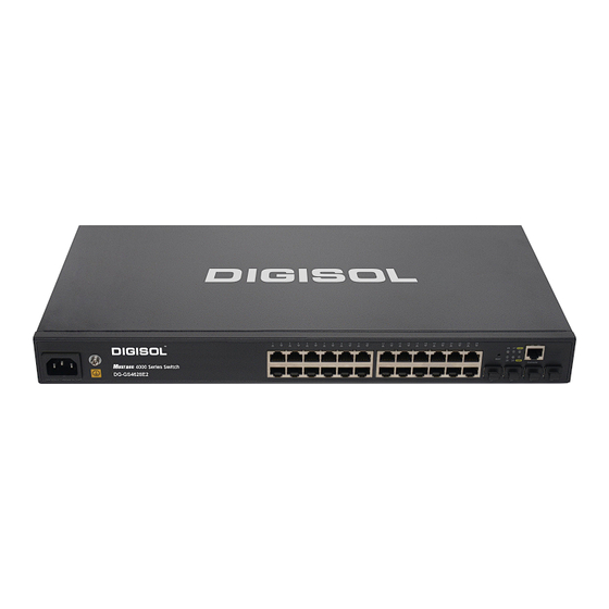
1.1 Product Brief DG-GS4628E2/DG-GS4628HPE-P switches are 1000Mb uplink layer 2 switches. DG-GS4628E2 provides 28 fixed ports (24 10/100/1000Base-T fixed ports and 4 1000Mb SFP ports). DG-GS4628HPE-P provides 28 fixed ports (24 10/100/1000Base-T fixed ports and 4 1000Mb SFP ports), supports 24 1000M ports of POE power supply. -
Page 4: Description Of Hardware
At least 21, 0000 hours MTBF 1.3 Description of Hardware 1.3.1 Front Panel DG-GS4628E2 provides 24 10/100/1000Base-T ports, 4 1000Mb SFP ports, 1 Console port, 1 system reset button, 30 LEDs, 1 220V AC power socket and 1 grounding screw. -
Page 5: Back Panel
DG-GS4628E2 / DG-GS4628HPE-P Installation Guide 1.3.2 Back Panel The back panel of DG-GS4628E2 is shown below: Fig 1- 14 Back Panel of DG-GS4628E2 The back panel of DG-GS4628HPE-P is shown below, and there is 1 220V AC power socket and 1 ground screw hole. - Page 6 The port is not link and PD not connected On (Green) SFP port is linked successfully Port25/26/27/28(Link/A port linked successfully, Flash (Green) receive/send data SFP port is not link 1.3.3.2 System Status Indicator Description Fig 1- 25 DG-GS4628E2 system LED diagram...
-
Page 7: Front Panel Port Description
DG-GS4628E2 / DG-GS4628HPE-P Installation Guide Table 1- 8 DG-GS4628E2 system indicator description Status Description On (Green) The internal power is operating normally Power Power is off or error On (Green) Operating state is abnormal DIAG Flash(Green) Operating state is normal... - Page 8 DG-GS4628E2 / DG-GS4628HPE-P Installation Guide Table 1- 13 DG-GS4628E2/DG-GS4628HPE-P port description Interface mode Spec RJ-45 port 10/100/1000Mbps auto negotiation MDI/MDI-X cable mode auto negotiation 5 kinds of UTP: 100 m SFP-SX-L transceiver 1000Base-SX SFP(850nm, MMF, 550m) ...
-
Page 9: Chapter 2 Hardware Installation
DG-GS4628E2 / DG-GS4628HPE-P Installation Guide Chapter 2 Hardware Installation 2.1 Installation Notice To ensure the proper operation of DG-GS4628E2/DG-GS4628HPE-P and your physical security, please read carefully the following installation guide. 2.1.1 Environmental Requirements The switch must be installed in a clean area. Otherwise, the switch may be damaged ... - Page 10 DG-GS4628E2 / DG-GS4628HPE-P Installation Guide Table 2- 1 Environmental Requirements: Dust content In addition, salt, acid and sulfide in the air are also harmful to the switch. Such harmful gases will aggravate metal corrosion and the aging of some parts. The site should...
- Page 11 DG-GS4628E2 / DG-GS4628HPE-P Installation Guide hours of continued operation and an annual cumulative total of less than 15 days. Formidable operation conditions refers to the ambient temperature and relative humidity value that may occur during an air-conditioning system failure, and normal operation conditions should be recovered within 5 hours.
-
Page 12: Installation Notice
DG-GS4628E2 / DG-GS4628HPE-P Installation Guide environment, will affect operations in various ways, such as capacitive coupling, inductive coupling, electromagnetic radiation, common impedance (including the grounding system) and cables/lines (power cables, signal lines, and output lines). The following should be noted: Precautions should be taken to prevent power source interruptions;... -
Page 13: Security Warnings
DG-GS4628E2 / DG-GS4628HPE-P Installation Guide regularly to extend the lifespan of the switch. 2.1.3 Security Warnings When using SFP transceiver, do not stare directly at the fiber bore when the switch is in operation. Otherwise the laser may hurt your eyes. -
Page 14: Installation Preparation
DG-GS4628E2 / DG-GS4628HPE-P Installation Guide seek help from the Medical Emergency using various ways. 2.2 Installation Preparation 2.2.1 Verify the Package Contents First, open the package, please check the contents of the switch container and accessory kit. (If you are concerned that any item is missing or an incorrect item has been supplied, please contact your dealer as soon as possible.) -
Page 15: Connecting Console
Do not block the blowholes on the switch to ensure the proper operation of the switch. 2.3.2 Connecting Console DG-GS4628E2/DG-GS4628HPE-P provide a RJ45 serial console port. Fig 2- 3 Connecting Console to switch The connection procedure is listed below:... -
Page 16: Sfp Transceiver Installation
Power on the switch and the character terminal. Configure the switch through the character terminal. 2.3.3 SFP Transceiver Installation DG-GS4628E2/DG-GS4628HPE-P provide multiple 1000Mb SFP transceiver slots. The procedure for installing the SFP transceiver is shown below: Step 1: Put on a ESD wrist strap (or antistatic gloves) Step 2: Insert the SFP transceiver to the guide rail inside the fiber interface line card. - Page 17 DG-GS4628E2 / DG-GS4628HPE-P Installation Guide Fiber cables should be connected as below: Step 1: Remove the protective plug from the SFP/XFP fiber transceiver bore; Remove the protective cap from one end of the fiber cable. Keep the fiber end clean and neat.
-
Page 18: Power Supply Connection
DG-GS4628E2 / DG-GS4628HPE-P Installation Guide 2.3.5 Power Supply Connection DG-GS4628E2/DG-GS4628HPE-P use the power is 220VAC. Please read the power input specification for the detailed information. Power supply connection procedure is described as below: Fig 2- 4 Connecting power to switch 1.
Need help?
Do you have a question about the DG-GS4628E2 and is the answer not in the manual?
Questions and answers