Table of Contents
Advertisement
Quick Links
Download this manual
See also:
User Manual
Advertisement
Table of Contents

Related Manuals for Digisol DG-GS1510HPEV2


Summary of Contents for Digisol DG-GS1510HPEV2
- Page 1 Hardware Installation Guide DG-GS1510HPEV2 Switch Hardware Installation Guide...
-
Page 2: Table Of Contents
Hardware Installation Guide Table of Content Chapter 1 Information of PoE Switch............................ 1 1.1 Standard configuration ............................1 1.2 POE Switch System Properties Parameters ......................1 Chapter 2 Preparing for installation ............................3 2.1 Safety notice ................................3 2.1.1 Ensure safety as the following principals ....................3 2.1.2 Safety warnings ............................ -
Page 3: Chapter 1 Information Of Poe Switch
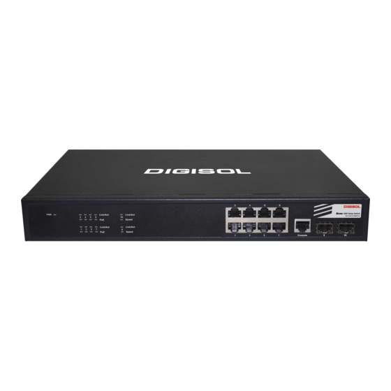
Hardware Installation Guide Information of PoE Switch This section explains the parameters of POE switch. Standard configuration POE switch standard ports consists of 3 parts: 8 Gigabit Ethernet interfaces witch PoE、 2 Giga Ethernet SFP interfaces and 1 Console interface. Refer to the following table: Features of standard ports: Port name Features... - Page 4 Hardware Installation Guide IEEE 802.1d Spanning Tree Protocol IEEE 802.1p Class of Service IEEE 802.1q tagged VLAN Standard IEEE 802.3x Flow control IEEE 802.3ad Link aggregation Protocol IEEE 802.3af RFC 1213 MIB II Network RFC 1493 Bridge MIB Management Standard RFC 1643 Ether-Like MIB 200 MHz MIPS32 8 10/100/1000M ports with PoE...
-
Page 5: Chapter 2 Preparing For Installation
Hardware Installation Guide Preparing for installation The following discusses the considering cases of switch installation, includes two sections: Please continue to read "switch Installation" after reading this section. Safety notice Ensure safety as the following principals Keep the chassis areas clean and dust-free during and after installation;... -
Page 6: Preventing Electrostatic Discharge Damage
Hardware Installation Guide Read the installation instructions carefully before you connect the system to its power source. Notes: Look carefully for possible hazards in your working area, such as moist floors,ungrounded power extension cable, frayed power cord. Locate the emergency power off switch for the room in which you are working. -
Page 7: Preventive Site Configuration
Hardware Installation Guide When planning your site layout and equipment locations, remember the precautions described in the next section, "Preventive Site Configuration". If you are experiencing shutdowns or unusually high errors with your existing equipment, this precautions might help you isolate the cause of failures and prevent future problems. ... -
Page 8: Chapter 3 Installing Switch
Hardware Installation Guide Installing switch This section explains the detail of POE Switch installation: Warning: Only qualified mechanics are allowed to install or replace the device. Installation tools and devices Tools and devices needed for POE switch are optional devices. Users have to buy according to their needs. -
Page 9: Connecting Console Port
Hardware Installation Guide Connecting Console port There is a console port on POE switch. This section explains the features and usage of the port. Speed: 115200bps, standard RJ 45 plug. Use dedicated cable to connect the port to PC parallel port. -
Page 10: Console Port Connection
Hardware Installation Guide Note: DG-GS1510HPEV2 switch Console Port does not support flow control. Therefore, “Data Flow Control” should be set “No” while using super terminal to manage switch. Console port connection This cable is used to connect POE switch console port to external terminal. One end is RJ45 8-pin plug. - Page 11 Hardware Installation Guide UTP port explanation is shown as follows: Pin NO. Description Name Note Data transmission positive and PoE TPTXD1+ Output Data transmission negative and PoE TPTXD1- Output Data receive positive and PoE TPRXD2+ Input Data receive negative and PoE TPRXD2- Input Data Bi-directional positive...
- Page 12 Hardware Installation Guide Note: Cable colors follow the regulation in EIA/TIA 568B. 10 -...
-
Page 13: Chapter 4 Hardware Troubleshooting
Hardware Installation Guide Hardware Troubleshooting Trouble analyzing The key to troubleshooting is to separate trouble from the system. By analyzing what system should do and what system is doing, troubleshooting becomes easy. Think of the following systems while analyzing troubles: ... - Page 14 Hardware Installation Guide port. 12 -...
- Page 15 Hardware Installation Guide 13 -...
Need help?
Do you have a question about the DG-GS1510HPEV2 and is the answer not in the manual?
Questions and answers