
Subscribe to Our Youtube Channel
Related Manuals for Digisol DG-GS4900 SERIES


Summary of Contents for Digisol DG-GS4900 SERIES
-
Page 1: Installation Guide
DG-GS4900 SERIES Installation Guide V1.0 2015-05-12 As our products undergo continuous development the specifications are subject to change without prior notice... -
Page 2: Table Of Contents
DG-GS4900 Series Installation Guide Index 1.1 O ..................... 3 VERVIEW 1.2 I ..............4 NTRODUCTION TO RODUCT 1.2.1 Product Overview ..................4 1.2.2 Features and Benefits ................4 1.3 P ..............5 HYSICAL PECIFICATIONS 1.4 D ..............6 ESCRIPTION OF ARDWARE 1.4.1 Front Panel .................... -
Page 3: Overview
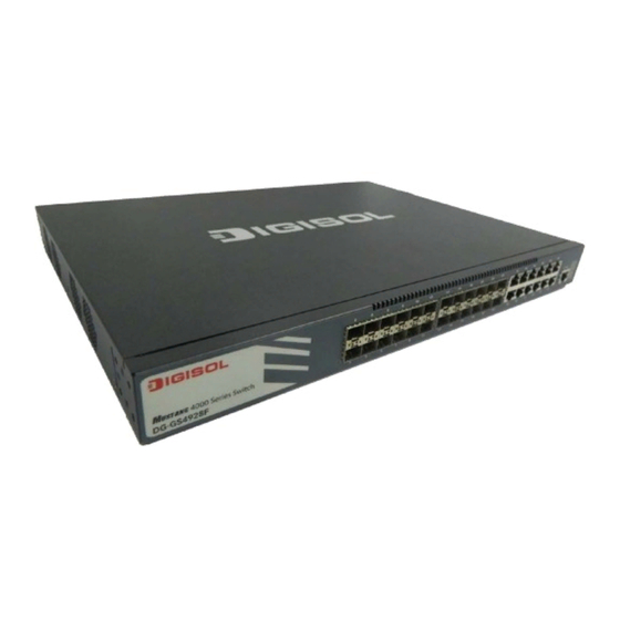
DG-GS4900 Series Installation Guide Chapter 1 Introduction 1.1 Overview DG-GS4900 series switches are ethernet switches. DG-GS4900 series switches are intelligent network management switches used by the network environment which need high performance, bigger port density and convenient installation. DG-GS4900 series switches include the following:... -
Page 4: Introduction To Product
CSMA/CD protocol, is a big leap in the evolution of Ethernet. 10Gb Ethernet can be deployed in star or ring topologies. DG-GS4900 series switches provide broad bandwidth and powerful processing capacity. It is suitable for metropolitan networks and wide area networks. -
Page 5: Physical Specifications
DG-GS4900 series switches fully support DiffServ Module. Users can specify a queue bandwidth on each port. WRR/SP/SWRR scheduling is also supported. DG-GS4900 series support the port trust. Users can configure trusted CoS, DSCP, IP precedence and port priority. User can also modify packet’s DSCP and COS values. The traffic can be classified by port, VLAN, DSCP, IP precedence and ACL table. -
Page 6: Description Of Hardware
DG-GS4900 Series Installation Guide • Power AC input: The rating voltage range: 100V~240V AC; 50/60HZ. • DC input: 48V DC input, -48V~-60V/DC; 2.5A Output power supply of PoE Do not support The max Power Consumption Support automatic timing Operating Temperature 0º~50ºC... -
Page 7: Back Panel
DG-GS4900 Series Installation Guide 1.4.2 Back Panel DG-GS4928F / DG-GS4928F / DG-GS4928F -R / supplies 2 plug-in interfaces, 1 -48V DC input power interface, 1 input power interface of PoE and 1 220V input power interface. DG-GS4928F supplies 2 interfaces with the extended card, 1 interface with -48V DC power input and 1 interface with 220V AC power input. -
Page 8: Dc Power/Poe Power(Specific Models Only) Input
DG-GS4900 Series Installation Guide 1.4.3 DC Power/PoE Power (specific models only) Input DG-GS4900 series support AC/DC input power backup and PoE power output. pin-outs signal of DC power and PoE power are distributed as below: Fig 1-6 Pin-outs Distribution of DC Input for DG-GS4928F... - Page 9 DG-GS4900 Series Installation Guide The other is system LEDs, they are used to show the work status of the system at the right of front panel. Panel Status Description Symbol On (Green) Power is operating normally Power is abnormally On (Green, blink) System is loading...
- Page 10 DG-GS4900 Series Installation Guide There is no this state Right LED No data is received or sent Blink Send or receive the data Table 1-5 SFP Port LEDs Panel Status Description Symbol On (Green) Power is operating normally Power is abnormally...
-
Page 11: Interface Description Of Front Panel
DG-GS4900 Series Installation Guide 1.4.5 Interface Description of Front Panel DG-GS4900 series switches provide RJ-45 1000Mb copper port and the interface of SFP 1000Mb fiber transceivers. Interface mode Spec • RJ-45 port 10/100/1000Mbps auto negotiation • MDI/MDI-X cable mode auto negotiation •... - Page 12 DG-GS4900 Series Installation Guide Figure 1-5 DG-SA-GS4900-2XFP structure diagram Each extended module’s panel diagram is shown as follows: Figure 1-6 panel diagram of DG-SA-GS4900-2XFP Figure 1-7 panel diagram of DG-SA-GS4900-2SFP+ Back panel diagrams of switch with extended modules are shown as follows:...
- Page 13 DG-GS4900 Series Installation Guide Extended module‘s LED descriptions are in the following: Status Description Green Ports are at link state with 10G Link/Activity Blink(Green) Ports are at active state with 10G No link or the link is failure Table 1-9 LED descriptions of 10Gb extended module Spec •...
-
Page 14: Installation Notice
DG-GS4900 Series Installation Guide Chapter 2 Hardware Installation 2.1 Installation Notice To ensure the proper operation for DG-GS4900 series and your physical security, please read carefully the following installation guide. 2.1.1 Environmental Requirements • The switch must be installed in a clean area. Otherwise, the switch may be damaged by electrostatic adherence. - Page 15 DG-GS4900 Series Installation Guide In addition, salt, acid and sulfide in the air are also harmful to the switch. Such harmful gases will aggravate metal corrosion and the aging of some parts. The site should S, NO , NH and Cl , etc.
- Page 16 DG-GS4900 Series Installation Guide continued operation and an annual cumulative total of less than 15 days. Formidable operation conditions refers to the ambient temperature and relative humidity value that may occur during an air-conditioning system failure, and normal operation conditions should be recovered within 5 hours.
-
Page 17: Installation Notice
Caution! If a standard 19’’ rack is not available, the DG-GS4900 series can be placed on a clean level desktop, leave a clearance of 100mm around the switch for ventilation, and do not place anything on top of the switch. -
Page 18: Installation Preparation
DG-GS4900 Series Installation Guide • Do not drop metals into the switch. It can cause short-circuit. • Do not touch the power plug and power socket. • Do not place the tinder near the switch. • Do not configure the switch alone in a dangerous situation, •... -
Page 19: Installation Guide
Fig 2-1 Install sketch map on the rack Please mount DG-GS4900 series on the 19’’ rack as below: 1. Attach the 2 brackets on the DG-GS4900 series with screws provided in the accessory kit. 2. Put the bracket-mounted switch smoothly into a standard 19’’ rack. Fasten the DG-GS4928F series to the rack with the screws provided. -
Page 20: Sfp Transceiver Installation
Power on the switch and the character terminal. Configure the switch through the character terminal. 2.3.3 SFP Transceiver Installation DG-GS4900 series provides multiple 1000Mb SFP transceiver slots. The procedure for installing SFP transceiver is shown below: Step 1: Put on a ESD wrist strap (or antistatic gloves). -
Page 21: Dg-Sa-Gs4900-2Xfp Extended Module Installation
DG-GS4900 Series Installation Guide 2.3.4 DG-SA-GS4900-2XFP Extended Module Installation DG-GS4900 series provide 10Gb slots. The procedure for installing the DG-SA-GS4900-2XFP module and the XFP 10Gb fiber transceiver is shown below: Step 1: Put on an ESD wrist strap (or antistatic gloves). -
Page 22: Copper Cable/Fiber Cable Connection
DG-GS4900 Series Installation Guide 2.3.6 Copper Cable/Fiber Cable Connection Copper cables should be connected as below: Step 1: Insert one end of the Ethernet cable to the RJ-45 Ethernet port in the copper cable line card of the switch; Step 2: Insert the other end of the Ethernet cable to the RJ-45 Ethernet port of other device;... -
Page 23: Ac Power Supply Connection
DG-GS4900 Series Installation Guide 2.3.7 AC Power Supply Connection DG-GS4900 series switches use 220V AC power supply by default. Please read the power input specification for the detailed information. AC Power supply connection procedure is described as below: 1. Insert one end of the power cable provided in the accessory kit into the power source socket (with overload and leakage protection), and the other end to the power socket in the back panel of the switch. -
Page 24: Dc Power Supply Connection
DG-GS4900 Series Installation Guide 2.3.8 DC Power Supply Connection DG-GS4900 series supports 220V AC input, 48V DC input or 220V AC, 48V DC input simultaneously. 48V DC input connection procedure is described as below: 1. Insert DC power linker provided in the accessory kit into DC power source socket in the back panel of the switch.
Need help?
Do you have a question about the DG-GS4900 SERIES and is the answer not in the manual?
Questions and answers