
Related Manuals for Digisol DG-GS4600SE2 Series


Summary of Contents for Digisol DG-GS4600SE2 Series
- Page 1 DG-GS4600SE2 Series GIGA LAYER 3 SWITCHES Installation Guide V1.0 2018-01-30 As our products undergo continuous development the specifications are subject to change without prior notice...
-
Page 2: Table Of Contents
DG-GS4600SE2 Installation Guide Content Chapter 1 INTRODUCTION............... 1-1 1.1 O .....................1-1 VERVIEW ...............1-1 1.2 I NTRODUCTION TO RODUCT 1.2.1 Product Overview..................... 1-1 1.2.2 Features and Benefits..................1-2 ................. 1-3 1.3 P HYSICAL PECIFICATIONS 1.4 D ..............1-5 ESCRIPTION OF ARDWARE 1.4.1 Front Panel......................1-5 1.4.2 Back Panel......................1-6 1.4.3 Status LEDs....................... -
Page 3: Chapter 1 Introduction
DG-GS4600SE2 Installation Guide Chapter 1 Introduction 1.1 Overview DG-GS4600SE2 series of ethernet switches are that a series of three layer line speed Ethernet switch products by self-development in DIGISOL ,intelligent network management switch used by the network environment which needs the... -
Page 4: Features And Benefits
10Gb Ethernet which adopts full-duplex technology instead of low-speed, half-duplex CSMA/CD protocol, is a big leap in the evolution of Ethernet. 10Gb Ethernet can be deployed in star or ring topologies. DG-GS4600SE2 series switches provide broad bandwidth and powerful processing capacity. It is suitable for metropolitan networks and wide area networks. -
Page 5: Physical Specifications
SSH protocol, ensure the configuration management security of the switch. Flexible Power Ensure System DG-GS4600SE2 series of switches support two AC power which have the b ackup function if one of them is fault. The power is hot swappable that improves the expansibility and flexibility of the power system. - Page 6 DG-GS4600SE2 Installation Guide supply of PoE max Power <30 W <440W(370W POE is the maximum power Consumption supply) Support automatic timing Support automatic timing 0℃~50℃ 0℃~50℃ Operating Temperature 10%~95% 10%~95% Relative Humidity Table 1- 2 Physical Specifications Item DG-GS4652SE2 Dimension (W * H * 440 x 44 x 240 D)(mm)...
-
Page 7: Description Of Hardware
DG-GS4600SE2 Installation Guide System power DG-GS4628FSE2 series support AC power input: AC input: The rating voltage range: 100V~240V AC; 50/60HZ The max voltage range: 90V~264V AC; 47HZ~63HZ DC input: voltage range: 11-13V current value: 4.5A Output power Do not support supply of PoE <40W max Power... -
Page 8: Back Panel
Fig 1- 6 Back Panel of DG-GS4628FSE2 1.4.3 Status LEDs LEDs of DG-GS4600SE2 series switch show the corresponding state. Mainboard LEDs include two parts, one is 24 1000M interface LEDs (including 4 combo ports), 4 SFP (combo optical port) interface LEDs and 4 SFP+ interface LEDs. They show each port state at RJ45 plug-in, each port corresponds a LED with double colors. -
Page 9: Interface Description Of Front Panel
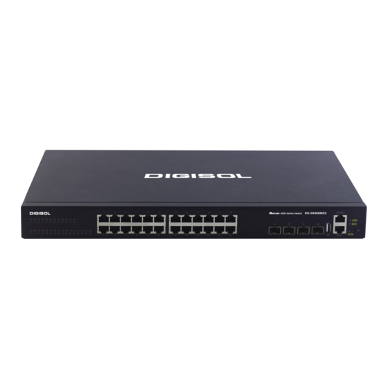
Power2 is operating normally PWR2 Power2 is not operating 1.4.4 Interface Description of Front Panel DG-GS4600SE2 series switches provide RJ-45 1000Mb copper port, interface of SFP+ 10Gb fiber transceivers and combo interface. Table 1- 7 interface descriptions Interface mode Spec RJ-45 port ... - Page 10 DG-GS4600SE2 Installation Guide SFP+ SFP+-LR transceiver 10GBase-LR SFP+ (1310nm, SMF, 10km) SFP+-SR transceiver 10GBase-SR SFP+ (850nm, 62.5μm MMF 32m, 50μm 500MHz/km MMF 85m, 50μm 2000MHz/km MMF 300m) SFP-GT SFP-GT Module: 1000Base-T SFP interface card module, RJ-45 interface Chapter 1-8...
-
Page 11: Chapter 2 Hardware Installation
2.1.1.1 Dust and Particles Dust is harmful to the safe operation of DG-GS4600SE2 series. Dust can lead to electrostatic adherence, especially likely under low relative humidity, causing poor contact of metal connectors or contacts. Electrostatic adherence will result in not only reduced product lifespan, but also increased chance of communication failures. - Page 12 DG-GS4600SE2 Installation Guide Table 2- 1 Environmental Requirements: Dust In addition, salt, acid and sulfide in the air are also harmful to the switch. Such harmful gases will aggravate metal corrosion and the aging of some parts. The site should avoid harmful gases, such as SO S, NO , NH...
- Page 13 DG-GS4600SE2 Installation Guide Caution! A sample of ambient temperature and humidity should be taken at 1.5m above the floor and 0.4m in front of the switch rack, with no protective panel covering the front and rear of the rack. Short term working conditions refer to a maximum of 48 hours of continued operation and an annual cumulative total of less than 15 days.
-
Page 14: Installation Notice
Caution! If a standard 19’’ rack is not available, the DG-GS4600SE2 series can be placed on a clean level desktop, leave a clearance of 100mm around the switch for ventilation, and do not place anything on top of the switch. -
Page 15: Installation Preparation
DG-GS4600SE2 Installation Guide in operation. Otherwise the laser may hurt your eyes. Do not attempt to conduct the operations which can damage the switch or which can cause physical injury. Do not install, move or disclose the switch and its modules when the switch is in ... -
Page 16: Installation Guide
Fig 2- 1 Install sketch map on the rack Please mount DG-GS4600SE2 series on the 19’’ rack as below: 1. Attach the 2 brackets on the DG-GS4600SE2 series with screws provided in the accessory kit. 2. Put the bracket-mounted switch smoothly into a standard 19’’ rack. Fasten the DG-GS4600SE2 series to the rack with the screws provided. -
Page 17: Sfp Transceiver Installation
Power on the switch and the character terminal. Configure the switch through the character terminal. 2.3.3 SFP Transceiver Installation DG-GS4600SE2 series provide multiple 1000Mb SFP transceiver slots. The procedure for installing SFP transceiver is shown below: Step 1: Put on a ESD wrist strap (or antistatic gloves). -
Page 18: Sfp+ Extended Module Installation
DG-GS4600SE2 Installation Guide 2.3.4 SFP+ extended module Installation DG-GS4600SE2 series provide 10Gb slots. The procedure for installing the SFP+ 10Gb fiber transceiver is shown below: Step 1: Put on an ESD wrist strap (or antistatic gloves). Step 2: Insert the SFP+ transceiver to the 10G optical port. Do not put the SFP+ transceiver up-side-down. -
Page 19: Ac Power Supply Connection
Do not stare at the fiber bore when the switch is in operation. That may hurt your eyes. 2.3.6 AC Power Supply Connection DG-GS4600SE2 series switches use 220V AC power supply by default. Please read the power input specification for the detailed information. AC Power supply connection procedure is described as below: 1. - Page 20 DG-GS4600SE2 Installation Guide Chapter 2-10...
Need help?
Do you have a question about the DG-GS4600SE2 Series and is the answer not in the manual?
Questions and answers