
Related Manuals for Digisol DG-GS4900SE Series


Summary of Contents for Digisol DG-GS4900SE Series
- Page 1 DG-GS4900SE Series Installation Manual V1.0 20/11/2016 As our products undergo continuous development the specifications are subject to change without prior notice...
-
Page 2: Table Of Contents
DG-GS4900SE Series Installation Guide Content 1.1 O ......................4 VERVIEW ................4 1.2 I NTRODUCTION TO RODUCT 1.2.1 Product Overview....................4 1.2.2 Features and Benefits..................5 1.3 P ................7 HYSICAL PECIFICATIONS 1.4 D ................. 9 ESCRIPTION OF ARDWARE 1.4.1 Front Panel......................9 1.4.2 Back Panel......................10... - Page 3 DG-GS4900SE Series Installation Guide 2.3.4 SFP+ extended module Installation............. 21 2.3.5 Copper Cable/Fiber Cable Connection............21 2.3.6 AC Power Supply Connection................22...
-
Page 4: Overview
DG-GS4900SE series switches are Ethernet switches. DG-GS4900SE series switches are intelligent network management switch used by the network environment which needs the high performance, the bigger port density and the convenient installation. DG-GS4900SE series switches include the types in the following: Name Type Description 20 copper ports +... -
Page 5: Features And Benefits
10Gb Ethernet which adopts full-duplex technology instead of low-speed, half-duplex CSMA/CD protocol, is a big leap in the evolution of Ethernet. 10Gb Ethernet can be deployed in star or ring topologies. DG-GS4900SE series switches provide broad bandwidth and powerful processing capacity. It is suitable for metropolitan networks and wide area networks. - Page 6 DG-GS4900SE Series Installation Guide queue bandwidth on each port. WRR/SP/SWRR scheduling is also supported. DG-GS4900SE series support the port trust. Users can configure trusted CoS, DSCP, IP precedence and port priority. User can also modify packet’s DSCP and COS values. The traffic can be classified by port, VLAN, DSCP, IP precedence and ACL table.
-
Page 7: Physical Specifications
4 10Gb optical ports Management ports 1 Console port, 1 network management port which supports 1000Mb rate System power DG-GS4900SE series support AC power input: AC input: The rating voltage range: 100V~240V AC; 50/60HZ The max voltage range: 90V~264V AC; 47HZ~63HZ... - Page 8 4 10Gb optical ports Management ports 1 Console port, 1 network management port which supports 1000Mb rate System power DG-GS4900SE series support AC power input: AC input: The rating voltage range: 100V~240V AC; 50/60HZ The max voltage range: 90V~264V AC; 47HZ~63HZ...
-
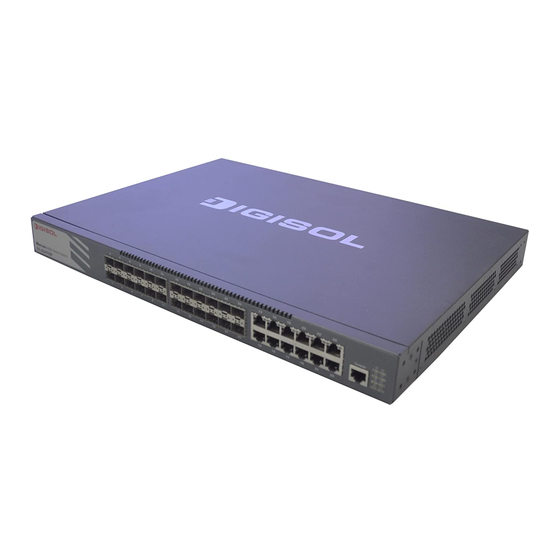
Page 9: Description Of Hardware
DG-GS4900SE Series Installation Guide 1.4 Description of Hardware 1.4.1 Front Panel DG-GS4928SE Ethernet switches provide 20 100/1000Base-TXauto negotiation ehternet ports, 4 1000Mb Combo ports, 4 10Gb optical ports, 4 function LEDs, 1 network management port, 1 alarm port, 1 USB interface, 1 mode button and 1 Console port. -
Page 10: Back Panel
DG-GS4900SE Series Installation Guide Fig 1- 3 Front Panel of DG-GS4952HPSE 1.4.2 Back Panel DG-GS4928SE supplies 1 ground screw hole and two power plug-in interfaces. Fig 1- 3Back Panel of DG-GS4928SE DG-GS4928HPSE2 supplies 1 ground screw hole, 1 fan and two power plug-in interfaces. -
Page 11: Interface Description Of Front Panel
The system mode is the default mode The fan is working normally The fan is working abnormally (DG-GS492 8HPSE2/52 HPSE supports) 1.4.4 Interface Description of Front Panel DG-GS4900SE series switches provide RJ-45 1000Mb copper port, interface of SFP+ 10Gb fiber transceivers and combo interface. - Page 12 DG-GS4900SE Series Installation Guide Table 1- 4 interface descriptions Interface mode Spec RJ-45 port 10/100/1000Mbps auto negotiation MDI/MDI-X cable mode auto negotiation 5 kinds of UTP: 100 m SFP+ SFP+-LR transceiver 10GBase-LR SFP+ (1310nm, SMF, 10km) ...
-
Page 13: Installation Notice
2.1.1.1 Dust and Particles Dust is harmful to the safe operation of DG-GS4900SE series. Dust can lead to electrostatic adherence, especially likely under low relative humidity, causing poor contact of metal connectors or contacts. Electrostatic adherence will result in not only reduced product lifespan, but also increased chance of communication failures. - Page 14 DG-GS4900SE Series Installation Guide Max Diameter (µm) Max Density 1.4×10 7×10 2.4×10 1.3×10 (particles/m³) Table 2- 1 Environmental Requirements: Dust In addition, salt, acid and sulfide in the air are also harmful to the switch. Such harmful gases will aggravate metal corrosion and the aging of some parts. The site should...
- Page 15 DG-GS4900SE Series Installation Guide The recommended temperature and humidity are shown below: Temperature: Relative humidity Long term condition Short term condition Long term condition Short term condition 15 ~ 30°C 0 ~ 50°C 40 ~ 65% 10 ~ 95% Table 2- 3 Environmental Requirements: Temperature and Humidity Caution! A sample of ambient temperature and humidity should be taken at 1.5m above the...
- Page 16 Caution! If a standard 19’’ rack is not available, the DG-GS4900SE series can be placed on a clean level desktop, leave a clearance of 100mm around the switch for ventilation, and do...
-
Page 17: Installation Notice
DG-GS4900SE Series Installation Guide 2.1.2 Installation Notice Read through the installation instruction carefully before operating on the system. Make sure the installation materials and tools are prepared. And make sure the installation site is well prepared. During the installation, users must use the brackets and screws provided in the ... -
Page 18: Installation Preparation
DG-GS4900SE Series Installation Guide Do not drop metals into the switch. It can cause short-circuit. Do not touch the power plug and power socket. Do not place the tinder near the switch. Do not configure the switch alone in a dangerous situation, ... -
Page 19: Installation Guide
Fig 2- 1 Install sketch map on the rack Please mount DG-GS4900SE series on the 19’’ rack as below: 1. Attach the 2 brackets on the DG-GS4900SE series with screws provided in the accessory kit. 2. Put the bracket-mounted switch smoothly into a standard 19’’ rack. Fasten the DG-GS4900SE series to the rack with the screws provided. -
Page 20: Connecting Console
DG-GS4900SE Series Installation Guide 2.3.2 Connecting Console DG-GS4900SE series provides a Mini-USB serial console port. Fig 2- 2 Connecting Console to switch The connection procedure is shown below: Find the console cable provided in the accessory kit. Attach the Mini-USB end to console port of the switch. -
Page 21: Sfp+ Extended Module Installation
2.3.4 SFP+ extended module Installation DG-GS4900SE series provide 10Gb slots. The procedure for installing the SFP+ 10Gb fiber transceiver is shown below: Step 1: Put on an ESD wrist strap (or antistatic gloves). -
Page 22: Ac Power Supply Connection
Do not stare at the fiber bore when the switch is in operation. That may hurt your eyes. 2.3.6 AC Power Supply Connection DG-GS4900SE series switches use 220V AC power supply by default. Please read the power input specification for the detailed information. AC Power supply connection procedure is described as below:... - Page 23 2. Check the power status indicator in the front panel of the switch. The corresponding power indicator should light. DG-GS4900SE series is self-adjustable for the input voltage. As soon as the input voltage is in the range printed on the switch surface, the switch can operate correctly.
Need help?
Do you have a question about the DG-GS4900SE Series and is the answer not in the manual?
Questions and answers