
Subscribe to Our Youtube Channel
Related Manuals for Digisol DG-GS4200 Series


Summary of Contents for Digisol DG-GS4200 Series
- Page 1 DG-GS4200 Series GIGA LAYER 2 SWITCHES Installation Guide V1.0 2018-09-24 As our products undergo continuous development the specifications are subject to change without prior notice...
-
Page 2: Table Of Contents
DG-GS4200 Installation Guide Content Chapter 1 Introduction ............. 1-1 1.1 Product Brief ................... 1-1 1.2 Physical Specifications ..............1-1 1.3 Description of Hardware ..............1-2 1.3.1 Front Panel ....................1-2 1.3.2 Back Panel ....................1-3 1.3.3 Status LEDs ..................... 1-3 1.3.4 Front Panel Port Description .............. -
Page 3: Chapter 1 Introduction
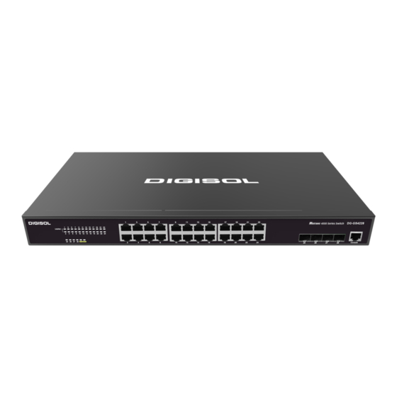
28 fixed ports (24 10/100/1000Base-T fixed ports and 4 1000Mb SFP ports). DG-GS4228P provides 28 fixed ports (24 10/100/1000Base-T fixed ports and 4 1000Mb SFP ports), support 24 1000M ports of POE power supply. DG-GS4200 series switches with advanced intelligent and secure features, can serve ideally as distribution layer switches for the access device of campus networks, enterprise networks and IP metropolitan networks. -
Page 4: Description Of Hardware
DG-GS4200 Installation Guide Storage Temperature -40°C~ 70°C Relative Humidity 5%~95%, no condensate Dimension DG-GS4228: W×D×H 440mm×230mm×44mm DG-GS4228P: W×D×H 440mm×260mm×44mm Weight DG-GS4228: 3.00±0.1kg DG-GS4228P: 4.20±0.1kg Average no trouble time At least 21, 0000 hours MTBF 1.3 Description of Hardware 1.3.1 Front Panel DG-GS4228 provides 24 10/100/1000Base-T ports, 4 1000Mb SFP ports,30 LEDs,1 Console port. -
Page 5: Back Panel
1 grounding screw. Fig 1-6 Back Panel of DG-GS4228P 1.3.3 Status LEDs DG-GS4200 series switches include port indicator and system status indicator, as shown in below and described in the following table. 1.3.3.1 Port Indicator Description Fig 1-7 DG-GS4228 LED diagram... - Page 6 DG-GS4200 Installation Guide On (Green) SFP port is linked successfully SFP port is linked successfully, and Port25-28(Link/Act) Flash (Green) receive/send data SFP port is not link Table 1-1 DG-GS4228 port indicator description Fig 1-8 DG-GS4228P LED diagram Table 1-2 DG-GS4228P port indicator description Panel Symbol Status Description...
-
Page 7: Front Panel Port Description
DG-GS4200 Installation Guide Fig 1-9 DG-GS4228 system LED diagram Table 1-3 DG-GS4228 system indicator description Status Description On (Green) The internal power is operating normally Power Power is off or error On (Green) Operating state is abnormal Flash(Green) Operating state is normal Power is off or system is abnormal Fig 1-10 DG-GS4228P system LED diagram Status... - Page 8 DG-GS4200 Installation Guide Each port description is shown below: Table 1-5 DG-GS4200 port description Interface mode Spec RJ-45 port 10/100/1000Mbps auto negotiation MDI/MDI-X cable mode auto negotiation 5 kinds of UTP: 100 m SFP-SX-L transceiver 1000Base-SX SFP(850nm, MMF, 550m) ...
-
Page 9: Chapter 2 Hardware Installation
DG-GS4200 Installation Guide Chapter 2 Hardware Installation 2.1 Installation Notice To ensure the proper operation of DG-GS4200 series and your physical security, please read carefully the following installation guide. 2.1.1 Environmental Requirements The switch must be installed in a clean area. Otherwise, the switch may be damaged by electrostatic adherence. - Page 10 DG-GS4200 Installation Guide In addition, salt, acid and sulfide in the air are also harmful to the switch. Such harmful gases will aggravate metal corrosion and the aging of some parts. The site should avoid harmful gases, such as SO S, NO , NH and Cl...
-
Page 11: Power Supply
DG-GS4200 Installation Guide operation conditions refers to the ambient temperature and relative humidity value that may occur during an air-conditioning system failure, and normal operation conditions should be recovered within 5 hours. 2.1.1.3 Power Supply It is adopted module switch power for the switch, the input parameters of power are shown below: The AC input voltage: 90~300VAC The frequency: 47Hz ~... -
Page 12: Installation Notice
DG-GS4200 Installation Guide and cables/lines (power cables, signal lines, and output lines). The following should be noted: Precautions should be taken to prevent power source interruptions; Provide the system with a dedicated grounding, rather than sharing the grounding with the electronic equipment or lightning protection devices. -
Page 13: Security Warnings
DG-GS4200 Installation Guide 2.1.3 Security Warnings When using SFP transceiver, do not stare directly at the fiber bore when the switch is in operation. Otherwise the laser may hurt your eyes. Do not attempt to conduct the operations which can damage the switch or which can cause physical injury. -
Page 14: Installation Preparation
DG-GS4200 Installation Guide 2.2 Installation Preparation 2.2.1 Verify the Package Contents First, open the package, please check the contents of the switch container and accessory kit. (If you are concerned that any item is missing or an incorrect item has been supplied, please contact your dealer as soon as possible.) 2.2.2 Required Tools and Materials The required tools and utilities are shown below:... -
Page 15: Connecting Console
Please place a rack shelf under the switch. Do not place anything on top of the switch. Do not block the blowholes on the switch to ensure the proper operation of the switch. 2.3.2 Connecting Console DG-GS4200 series provide a RJ45 serial console port. Fig 2-3 Connecting Console to switch The connection procedure is listed below: Find the console cable provided in the accessory kit. -
Page 16: Sfp Transceiver Installation
DG-GS4200 Installation Guide character terminal. 2.3.3 SFP Transceiver Installation DG-GS4200 series provide multiple 1000Mb SFP transceiver slots. The procedure for installing the SFP transceiver is shown below: Step 1: Put on a ESD wrist strap (or antistatic gloves) Step 2: Insert the SFP transceiver to the guide rail inside the fiber interface line card. -
Page 17: Power Supply Connection
2. Check the power status indicator in the front panel of the switch. The corresponding power indicator should light. DG-GS4200 series is self-adjustable for the input voltage. As soon as the input voltage is in the range printed on the switch surface, the switch can operate correctly. - Page 18 DG-GS4200 Installation Guide Caution! The input voltage must be within the required range, otherwise the switch can be damaged or malfunction. Do not open the switch shell without permission. It can cause physical injury. 2-10...
- Page 19 DG-GS4200 Installation Guide 2-11...
Need help?
Do you have a question about the DG-GS4200 Series and is the answer not in the manual?
Questions and answers