Table of Contents
Advertisement
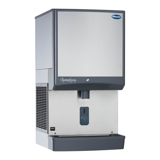
12CI425A-L
countertop dispenser
Following installation, please forward this manual
1
Symphony Plus
Ice and Water Dispensers
12CI425A-LI
countertop, ice-only
dispenser
12CI425A-S
countertop dispenser with
SensorSAFE infrared dispensing
(shown with legs accessory)
to the appropriate operations person.
801 Church Lane • Easton, PA 18040, USA
Toll free (877) 612-5086 • +1 (610) 252-7301
www.follettice.com
Operation and Service Manual
12CI425A-SI countertop, ice-only
dispenser with SensorSAFE
infrared dispensing
12 Series
™
™
12HI425A-S
wall mount dispenser
(available with or without
drain pan)
12CI425A • 12HI425A
01033653R00
Advertisement
Table of Contents

Subscribe to Our Youtube Channel
Related Manuals for Follett 12CI425A-LI


Summary of Contents for Follett 12CI425A-LI
- Page 1 Symphony Plus 12 Series ™ Ice and Water Dispensers Operation and Service Manual 12CI425A-LI 12CI425A-SI countertop, ice-only countertop, ice-only dispenser with SensorSAFE ™ dispenser infrared dispensing 12CI425A-L 12HI425A-S 12CI425A-S countertop dispenser wall mount dispenser countertop dispenser with (available with or without...
-
Page 2: Table Of Contents
Welcome to Follett........ -
Page 3: Welcome To Follett
Before you begin After uncrating and removing all packing material, inspect the equipment for concealed shipping damage. If damage is found, notify the shipper immediately and contact Follett Corporation so that we can help in the filing of a claim, if necessary. -
Page 4: Specifications
Specifications 22.625" (57.5 cm) air exhaust 32.00" (82.6 cm) 3/4" MPT drain 3/8" FPT water inlet intake 4.00" 18.00" 16.00" (10.2 cm) (45.8 cm) power cord (NEMA 5-15) (40.7 cm) 23.5" (59.7 cm) Front View Side View Rear View Electrical §... -
Page 5: Installation
Installation Before you begin § All dispensers must be installed level in both directions to ensure proper operation. § Service and ventilation clearances: 6" (15.3 cm) on right side of dispenser, 6" (15.3 cm) at top for ventilation and 12" (30.5 cm) at top recommended for service. §... -
Page 6: Installing Countertop Dispensers With Legs Accessory
Installing countertop dispensers with legs accessory (P/N AF10LBLEGS) CAUTION! § Do not tilt any unit further than 30° off vertical plane. § Countertop dispensers that sit on legs (not bolted to counter) can be inadvertently moved. Care should be taken when operating and cleaning to avoid accidents. 1. - Page 7 Fig. 4 – Wall mount bracket and fastener requirements wall mounting bracket support bracket screw = Customer supplied. 12CI425A • 12HI425A...
- Page 8 Fig. 5 – Wall-mount dimensions Fig. 6 – Wall mount side view FRONT VIEW 23.70" (60.2 cm) 16.00" TYP. (40.6 cm) WALL STUDS ANCHOR POINTS 0.438" (11 mm) CLEARANCE WALL MOUNT 13.00" (33.0 cm) BRACKET 15.08" (38.3 cm) 32.00" (81.3 cm) 13.50"...
-
Page 9: User Information
User information How the dispenser works Follett’s 12 series automatic-load ice and water dispensers are equipped with Follett’s 425 lb (193 kg)/day ice machine. In the continuous icemaking process, water freezes to the inside wall of the evaporator. A rotating stainless steel auger carries the ice to the top of the evaporator where it is compressed and extruded through an outlet port. -
Page 10: Panel Removal
Panel removal Fig. 10 Fig. 11 Top cover: Lift cover up and off Velcro strips. Front cover: Pull bottom of cover, then lift cover up and forward to unhook from keyhole slots. Fig. 12 Fig. 13 Splash panel: Remove 4 screws. Pull out bottom Side panels: Remove screw located on lower rear of panel to allow top to slide out from under hopper side. -
Page 11: Cleaning/Descaling And Sanitizing
Cleaning of the condenser can usually be performed by facility personnel. Cleaning/descaling and sanitizing of the ice machine system should be performed by your facility’s trained maintenance staff or a Follett authorized service agent. Regardless of who performs the cleaning, it is the operator’s responsibility to see that this cleaning is performed according to the schedule below. - Page 12 Cleaning Solution: Mix cleaning solution of 1 gal. (3.8 L) 100 F (38 C) water and 7 oz (198 g) (one 7 oz packet) of Follett SafeCLEAN ice machine cleaner/descaler (P/N 00132001). Sanitizing Solution: Mix a sanitizing solution of 1 gal. (3.8 L) 100 F (38 C) water and 1.6 oz (47 ml) Nu-Calgon IMS-II Sanitizer (P/N 00979674).
-
Page 13: Sanitizing Procedure
Sanitizing procedure 10. Press CLEAN switch. The MAINTENANCE light and LOW WATER light will turn on. 11. Fill cleaning cup with sanitizing solution until it overflows from the ice transport tube into the hopper. Place lid back on cup. Save remainder of sanitizing solution. 12. -
Page 14: Service
Service Ice machine operation (all models) Follett’s ice machine consists of four distinct functional systems: § Harvesting system § Refrigeration system § Water system § Electrical control system These four systems work together to accomplish the production and harvesting of ice. A problem in any one of these systems will result in improper operation of the entire ice production cycle. -
Page 15: Water System
Water system The water level in the evaporator is controlled by a fill solenoid (Fig. 14) and level detecting sensors. Water sensing rods (Fig. 15) extend down into the reservoir at the end of the evaporator assembly. The system works via electrical conductivity as follows: One of the longest probes is a common. - Page 16 Fig. 15 – Water level diagram 1 COMMON 2 HIGH 3 ALARM LOW 4 LOW NORMAL OPERATING RANGE Access to electrical box and control board The 12 series electrical box has been designed to slide out for easy access to the control board and more convenient troubleshooting.
- Page 17 Control board DIP switch settings OFF POSITION ON POSITION Sleep cycle dispense duration Sleep cycle Sleep cycle enabled disabled Not used Not used 35 s Sleep cycle Sleep cycle dispense duration dispense duration 60 min. time delay 20 min. time delay 15 s 60 s Flush enabled...
-
Page 18: Wiring Diagram
Wiring diagram POWER SWITCH BLACK #19 L2/N WHITE #22 WHITE #2 BLACK #23 GND TO WHITE #26 WHITE # BLACK #24 MAIN FRAME BLACK #25 GRN #27 SENSORSAFE ONLY LEVER ONLY BLACK #25 BLACK #24 GRN #20 CLEAN SWITCH COMPONENTS BLACK #29 BLACK #28 MOUNTED ON... - Page 19 BLACK #19 WHITE #22 BLACK #23 BLACK #23 WHITE #26 BLACK #24 BLACK #51 ICE AUX WATER AUX POWER LOW BIN BLACK #01 MAKING ICE SLEEP CYCLE HI PRS TIME DELAY BLACK #21 (SENSORSAFE) LOW WATER BLACK #25 (LEVER) MAINTENANCE MODEL SELECT SERVICE HI AMPS...
-
Page 20: Wiring Diagram - Lever Only
Wiring diagram - Lever only POWER SWITCH BLACK #19 L2/N BLACK #23 WHITE #26 GND TO BLACK #24 BLACK #25 MAIN FRAME GRN #27 COMPONENTS BLACK #28 MOUNTED ON BLACK #29 SPLASH PANEL LEVER ONLY WATER STATION SWITCH BLACK #30 ICE STATION BLACK #31 SWITCH... -
Page 21: Wiring Diagram - Sensorsafe Only
Wiring diagram - SensorSAFE only POWER SWITCH BLACK #19 L2/N WHITE #22 BLACK #23 WHITE #26 GND TO MAIN FRAME SENSORSAFE ONLY GRN #27 BLACK #25 BLACK #24 GRN #20 CLEAN SWITCH COMPONENTS MOUNTED ON SPLASH PANEL WATER SENSOR SENSOR SENSORSAFE ONLY COMPONENTS MOUNTED ON... -
Page 22: Ice Machine Operational And Diagnostic Sequences
Ice machine operational and diagnostic sequences The wiring diagrams that follow illustrate the circuitry of Follett ice machines used with 12 series ice dispensers. Both normal operation (stages 1–8) and non-normal diagnostic sequences showing torque-out for use in troubleshooting are shown. - Page 23 Normal operation – Stage 2 When continuity is seen between B and C, the water valve de-energizes, the AUGER output (P4) comes on along with the MAKING ICE LED. The auger gearmotor’s start windings are energized through a current style start relay that is pulled in by the initial high current draw of the gearmotor.
- Page 24 Normal operation – Stage 4 One second (1 s) after the fan comes on, the COMPRESSOR output comes on. The compressor circuit uses both run and start capacitors along with a potential start relay. The start capacitor in energized through the normally closed contacts of the start relay.
- Page 25 Normal operation – Stage 6 Once the bin thermostat control opens, the LOW BIN LED goes out. After a 10 second delay the compressor output turns off, the MAKING ICE LED goes out and the TIME DELAY LED comes on. T.O.L.
- Page 26 Normal operation – Stage 8 When the dwell time of 20 minutes has expired, the TIME DELAY LED goes off. If 5 seconds of ice has been dispensed and the SLEEP CYCLE LED is off, the ice machine will go through the normal start-up sequence when the bin level control signals the control board for ice.
-
Page 27: Diagnostic Stages
T.O.L. High Pressure Switch Compressor Start Relay WHITE Compressor Electrical Box WHITE Start POWER Relay Drain Fill LOW BIN BLACK Valve Valve MAKING ICE SLEEP CYCLE HI PRS TIME DELAY 1 2 3 4 5 6 7 8 LOW WATER YELLOW BLACK MAINTENANCE... - Page 28 High gearmotor amps – Stage 2 If the restart is successful the board will continue to monitor the current draw on P4 for 60 minutes looking for a second high amps (above 3A) occurrence. If the ice machine runs without problems for 60 minutes and no additional torque errors occur, the ice machine will continue normal operation.
- Page 29 Loss of water During operation, the water level cycles between the normal low (D) and normal high (C) water probes - the fill valve (P21) cycling on and off. If continuity is not detected between the common probe (B) and normal low (D) within 10 seconds, the LOW WATER and TIME DELAY LEDs will come on and the machine will shut down for the one hour time delay period.
- Page 30 High refrigerant pressure Should the refrigeration pressure rise above 425 psi, the high pressure switch contacts will open. The board sees the open circuit and the HIGH PRESSURE and TIME DELAY LEDs will come on, the machine shuts down. After the one hour time delay, the machine will attempt to restart. If the pressure has fallen below the reset point of 295 psi and the board see the contacts closed, the machine will resume normal operation.
-
Page 31: Refrigeration Pressure Data
Refrigeration cycle low side service port condenser high pressure high side switch compressor service port filter dryer evaporator high high pressure pressure pressure pressure thermostatic vapor liquid liquid vapor expansion valve Refrigeration pressure data Compressor data Air-cooled ice machine capacity/24 hrs. Ambient Air Temperature ˚F/˚C Compressor current draw Air-cooled... -
Page 32: Refrigeration System
§ Recharging of unit at other than factory specifications will void ice machine warranty. Refrigerant replacement requirements 1. Non-contaminated refrigerant removed from any Follett refrigeration system can be recycled and returned to the same system after completing repairs. Recycled refrigerant must be stored in a clean, approved storage container. -
Page 33: Dispenser Troubleshooting
Dispenser troubleshooting CAUTION! § Disconnect power to unit before putting hands or arms in storage area or attempting any repair or service to equipment. Before calling for service 1. Check that no ice is in the dispenser bin area. 2. Check that congealed ice is not causing a jam 3. -
Page 34: Disassembly And Replacement Instructions
SensorSAFE board guide Fig. 17 LEDs, when illuminated, indicate the following: PWR (board power), CLN (clean button pressed WTR and WM outputs disabled), ICE (ice dispensing activated), WTR (water dispensing activated). Terminals: L1 (incoming power, hot), L2 (neutral terminals), WTR (power terminal for water solenoid), WM (power terminal for wheelmotor), CLN (terminals for clean cycle switch). - Page 35 Fig. 19 12CI425A • 12HI425A...
- Page 36 Evaporator disassembly Note: The upper bearing, lower bearing and auger assemblies must be replaced as assemblies. The bottom and top bearing assemblies cannot be field assembled to factory specifications. 1. Press CLEAN switch. Fig. 20 2. Wait for LOW WATER light to illuminate. 3.
- Page 37 Evaporator reassembly Fig. 21 1. Clean gearmotor boss, output shaft and shaft well. Apply grease in well 2. Install drain pan and evaporator mounting base. 3. Fill gearmotor shaft well with food grade grease (Fig. 21). 4. Install condensate shield and seat against gearmotor boss.
-
Page 38: Fan Removal
Fan removal 1. Remove 4 fan mounting screws and 3 drain Fig. 24 tubes from bracket. REMOVE DRAIN TUBES FROM DRAIN CAP. REMOVE DRAIN CUP AND CAP. REMOVE FAN BASE MOUNTING SCREWS. 2. Rotate fan mounting bracket toward back of Fig. -
Page 39: Thermostat And Ice Transport Tube Replacement
Thermostat and ice transport tube replacement ice tube 3" (76 mm) retainer 2" (51 mm) 0.50 TYP ice tube gasket capillary tube bracket Thermostat: hand bend cap tube end as shown Ice transport tube: tube may extend a maximum of 1/4" (6 mm) into ice bin Ice transport tube replacement 1. -
Page 40: Replacement Parts
Replacement parts Dispenser exterior Reference # Description Part # Cover, front, ice and water 01064575 Not shown Cover, front, ice only 01064583 Louver, intake, plastic 00967117 Not shown Grille, drain pan, gray plastic 01051614 Drain pan, plastic 00967059 Drain pan assembly (includes hardware, pan and grille) 502410 Panel, rear 502394... -
Page 41: Wheelmotor And Drive System
Wheelmotor and drive system Reference # Description Part # Motor, wheel, long shaft (includes 502537) 502580 Baffle, ice (securing hardware, part# 00167973, included) 502414 Wheel with Agion, agitator 502387 Rod, threaded (includes knurled nut) 502390 Agitator, rotating 502386 See page 39 Bracket, capillary tube 502406 See page 39... -
Page 42: Dispense Chute And Splash Panel (Models With Lever Dispensing)
Dispense chute and splash panel (models with lever dispensing) Reference # Description Part # Chute, ice or water (with Agion antimicrobial product protection 00967760 ® Support, water tube 00960682 Lever 00976845 Boot, dispense switch button 502418 Screw, panel 00982421 Switch, dispense 00981217 Bracket, lever support 00958793... -
Page 43: Dispense Chute And Splash Panel (Models With Sensorsafe Infrared Dispensing)
Dispense chute and splash panel (models with SensorSAFE infrared dispensing) Reference # Description Part # Chute, ice or water (with Agion) 00967760 Sensor (includes lens and Ty-rap*) 00122978 Support, water tube 00960682 Screw, panel 00982421 Fitting, bulkhead (with nut) 00976787 Tube, water solenoid 502420 Not shown... -
Page 44: Ice Machine Components
Ice machine components Rear view Right side view Top view (lower section) Left side view 12CI425A • 12HI425A... - Page 45 Reference # Description Part # Drier 502724 Coil, condenser (includes shroud) 01065317 Reservoir, assembly 01064682 Not shown Gasket, reservoir 00990978 Evaporator (see page 48 for detailed drawing) — Drain pan, evaporator 502727 Valve, expansion, thermal 502726 Valve, shut-off, water, plastic, 1/4" 01035526 Gearbox &...
-
Page 46: Electrical Components
Electrical components Reference # Description Part # Board, control circuit, 115 V, 60 Hz 01064708 Switch, clean 00117036 Switch, rocker, power 502209 Switch, rocker, bin signal 502209 Switch, cleaning, SensorSAFE models 502409 Control board, SensorSAFE models 502242 Bin thermostat 500514 12CI425A •... -
Page 47: Compressor
Compressor Reference # Description Part # Compressor, 120 V (includes start cap, run cap, and start relay) 01065259 Capacitor, start 01026145 Cap, end 01027556 Overload, compressor 01027572 Capacitor, run 00997759 Relay, start 00997726 12CI425A • 12HI425A... -
Page 48: Evaporator Replacement Parts
Evaporator replacement parts HEALTHCARE 12CI425A • 12HI425A... - Page 49 Reference # Description Part # Coupling, vee band, includes nut 502735 Bearing assembly, top 502736 Loop, ice compression, beveled 502110 Auger (see below for Flaker-specific components) 502737 Evaporator (includes insulation jacket, and top bearing insulation) 01064658 O ring, bearing housing 500496 Bearing assembly, bottom (includes O rings and condensate shield) 502738...
-
Page 50: Water Supply And Drains
Water supply and drains Reference # Description Part # Tube, reservoir clean 00998765 Tube, nozzle vent 01027804 Cup, clean 01065226 Tube, nozzle drain 01027796 Tube, purge 01054790 Tube, bin 01054782 Tube, evaporator fill 00998740 Tube, evaporator drain pan 01054154 Solenoid, purge 00991216 Reservoir 01064682... -
Page 51: Water Treatment Accessories For Symphony Plus Ice And Water Dispensers
Description Part # Standard capacity filter system Not shown Follett QC4-FL4S water filter system (includes FL4S primary cartridge and head, coarse 00130229 pre-filter and head, pressure gauge, flushing valve; assembled and installed on mounting bracket), one per ice machine Not shown... - Page 52 SafeCLEAN, SensorSAFE, Maestro Plus, Symphony Plus, Quiet Night and Sani-Sponge are trademarks of Follett Corporation. Follett and RIDE are registered trademarks of Follett Corporation, registered in US. 801 Church Lane • Easton, PA 18040, USA 01033653R00 Toll free (877) 612-5086 • +1 (610) 252-7301 ©...
Need help?
Do you have a question about the 12CI425A-LI and is the answer not in the manual?
Questions and answers