Follett 110 Installation & Service Manual
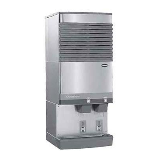
Symphony 110 series – 220 v 60 hz/230 v 50 hz ice and water dispensers
Hide thumbs
Also See for 110:
- Installation & service manual (28 pages) ,
- Operating & parts manual (21 pages)
Table of Contents
Advertisement
Order parts online
www.follettice.com
C/E110CT400A/W
Following installation, please forward this manual
110 Series – 220 V 60 Hz/230 V 50 Hz
Installation, Operation and Service Manual
C/E110CR400A/W
to the appropriate operations person.
801 Church Lane • Easton, PA 18044, USA
Toll free (877) 612-5086 • +1 (610) 252-7301
www.follettice.com
Ice and Water Dispensers
C/E110FB400A/W
00109520R05
Advertisement
Table of Contents
Troubleshooting

Related Manuals for Follett 110


Summary of Contents for Follett 110
- Page 1 110 Series – 220 V 60 Hz/230 V 50 Hz Ice and Water Dispensers Order parts online Installation, Operation and Service Manual www.follettice.com C/E110CT400A/W C/E110CR400A/W C/E110FB400A/W Following installation, please forward this manual to the appropriate operations person. 801 Church Lane • Easton, PA 18044, USA Toll free (877) 612-5086 •...
-
Page 2: Table Of Contents
Dispense chute and splash panel areas – SensorSAFE models Electrical box – SensorSAFE models Wheel motor and drive system Hopper components Chilled water components Solenoid dispense assembly 110 Series 220 V 60 Hz/230 V 50 Hz Ice and Water Dispensers... -
Page 3: Before You Begin
• Ice is slippery. Be sure counters and fl oors around dispenser are clean, dry and free of ice. • Ice is food. Follow recommended cleaning instructions to maintain cleanliness of delivered ice. 110 Series 220 V 60 Hz/230 V 50 Hz Ice and Water Dispensers... -
Page 4: Specifi Cations
Countertop models with integral ice machine (C/E110CT400A/W) – 153mm (6") at top. 153mm (6") each side advised for service. Freestanding models (C/E110FB400A/W) – 102mm (4") at rear. 305mm (12") at top advised for service. 110 Series 220 V 60 Hz/230 V 50 Hz Ice and Water Dispensers... -
Page 5: Field Wiring
220 V 60 Hz, 6.5A E110CT400A/W 230 V 50 Hz, 6.5A C110CR400A/W cord provided 220 V 60 Hz E110CR400A/W 230 V 50 Hz dispenser: 1.5A ice machine: 5.0A 110 Series 220 V 60 Hz/230 V 50 Hz Ice and Water Dispensers... -
Page 6: Installation
11. Turn on water supply and check that water level in fl oat reservoir (when full) is within 6mm (1/4") of mark on side of reservoir and that fl oat moves freely. Check for leaks. 110 Series 220 V 60 Hz/230 V 50 Hz Ice and Water Dispensers... - Page 7 18. Remove dispenser hopper lid; clean and sanitize dispenser according to instructions. 19. Turn ice machine bin signal switch on and replace front covers, securing with screws. 110 Series 220 V 60 Hz/230 V 50 Hz Ice and Water Dispensers...
-
Page 8: Installing Countertop Dispensers
(J) 3/8" FPT place. water inlet drain pan 110 Series 220 V 60 Hz/230 V 50 Hz Ice and Water Dispensers... - Page 9 Important: Do not connect condenser drain line to any other drain lines. 21. Proceed with either RIDE or top-mounted ice machine connection instructions, as appropriate. 3/4" FPT dispenser drain 110 Series 220 V 60 Hz/230 V 50 Hz Ice and Water Dispensers...
-
Page 10: Installing Ride Ice Machines
Dispensers with top mount ice machines cannot be mounted on legs. They must be bolted to counter. Use gloves when lifting ice machine to protect hands from sheet metal edges. 110 Series 220 V 60 Hz/230 V 50 Hz Ice and Water Dispensers... - Page 11 Fig. 8 – Ice transport tube and ice level control stat mounting for units with top-mounted ice machines 19mm ice level control stat (.75") Hand bend cap tube end to approximately. 45° as shown 45° 110 Series 220 V 60 Hz/230 V 50 Hz Ice and Water Dispensers...
-
Page 12: User Information
How the dispenser works Follett’s 110 series automatic load ice and water dispensers receive ice from Follett’s 181kg (400 lb)/day ice machine located in the dispenser base, in the cabinet top or in a remote location up to 6m (20 ft) away. Ice produced is stored in the bin section of the dispenser. - Page 13 To ensure that your ice machine and dispenser are cleaned/descaled and sanitized properly, proceed as follows: 1. Clean/descale the ice machine 2. Sanitize the ice machine 3. Clean/descale the dispenser 4. Sanitize the dispenser 110 Series 220 V 60 Hz/230 V 50 Hz Ice and Water Dispensers...
- Page 14 12. If so equipped, turn ice machine ON and begin to make ice (ice machine should start immediately with power and bin signal supplied). 13. After approximately 30 minutes, test dispenser for proper dispensing. 110 Series 220 V 60 Hz/230 V 50 Hz Ice and Water Dispensers...
-
Page 15: Service Information
SWITCH SWITCH WHITE T-STAT TIMER WHITE B RLY A WHITE RELAY #1 WHITE PURPLE ORANGE WHITE BLUE WHITE ICE MACHINE BIN SIGNAL (16 VDC) RELAY #2 ORANGE 110 Series 220 V 60 Hz/230 V 50 Hz Ice and Water Dispensers... -
Page 16: Wiring Diagram - Sensorsafe ™ Models
TIMER WHITE WHITE B RLY RELAY #1 WHITE CLEAN YELLOW SWITCH YELLOW WHITE ORANGE NEUTRAL BLUE WHITE WHITE ICE MACHINE BIN SIGNAL (16 VDC) RELAY #2 ORANGE 110 Series 220 V 60 Hz/230 V 50 Hz Ice and Water Dispensers... -
Page 17: Dispenser Troubleshooting
6. Ice dispenses by a. Faulty dispense gate a. Replace dispense gate itself b. Faulty dispense solenoid b. Replace dispense solenoid c. Faulty dispense switch c. Replace dispense switch 110 Series 220 V 60 Hz/230 V 50 Hz Ice and Water Dispensers... -
Page 18: Troubleshooting Sensorsafe Board And Sensors
If there is power on any output terminal (WTR, SOL or WM) on control board, replace board Remove lens protective cover; adjust funnel so water doesn’t drip down lens or behind splash panel 110 Series 220 V 60 Hz/230 V 50 Hz Ice and Water Dispensers... -
Page 19: Disassembly And Replacement Instructions
Disconnect wiring to splash panel. 4. Disconnect wires on motor. 5. Remove four bolts (7/16" socket) holding motor assembly to bottom of dispenser. 6. Remove motor assembly. 110 Series 220 V 60 Hz/230 V 50 Hz Ice and Water Dispensers... -
Page 20: Ice Transport Tube Replacement
7. Install supplied insulation to run of transport tube required for your site, leaving approximately 51mm (2") of tube exposed at free end. 8. Check that insulated tube runs continuously uphill to dispenser with no dips. 110 Series 220 V 60 Hz/230 V 50 Hz Ice and Water Dispensers... - Page 21 10. Fasten tube on port with hose clamp, being sure that clamp is positioned on evaporator side of nozzle fl ange. 11. Tighten clamp. ice level control stat engaging pin capillary tube 26mm (1") ice tube ice hose mounting bracket 5mm (3/16") ice tube hole 110 Series 220 V 60 Hz/230 V 50 Hz Ice and Water Dispensers...
-
Page 22: Thermostat Locations
110 Series 220 V 60 Hz/230 V 50 Hz Ice and Water Dispensers... -
Page 23: Parts
Dispenser exterior Reference Description Part # Cover, top front, 110 countertop (CT) 502756 Cover, top front, 110 countertop unit with RIDE ice machine (CR) & freestanding (FB) 502703 Cover, lower section, 110 freestanding (FB) units 502704 Cover, dispense chute 502681... -
Page 24: Dispense Chute And Splash Panel Areas - Lever Models
1 Disclaimer: Antimicrobial protection is limited to the treated components and does not treat water or ice. Agion is a registered trademark of Agion Technologies, Inc, Wakefi eld, MA, USA. 110 Series 220 V 60 Hz/230 V 50 Hz Ice and Water Dispensers... -
Page 25: Electrical Box - Lever Models
Thermostat, bin level 501375 Level fi ll relay 502209 Switch, dispenser power 502209 Switch, ice machine bin signal 501375 Bin signal relay 501700 Level fi ll timer 110 Series 220 V 60 Hz/230 V 50 Hz Ice and Water Dispensers... -
Page 26: Dispense Chute And Splash Panel Areas - Sensorsafe Models
1 Disclaimer: Antimicrobial protection is limited to the treated components and does not treat water or ice. Agion is a registered trademark of Agion Technologies, Inc, Wakefi eld, MA, USA. 110 Series 220 V 60 Hz/230 V 50 Hz Ice and Water Dispensers... -
Page 27: Electrical Box - Sensorsafe Models
Level fi ll relay 501375 Switch, dispenser power 502209 Switch, ice machine bin signal 502209 Bin signal relay 501375 Level fi ll timer 501700 SensorSAFE Board 502915 110 Series 220 V 60 Hz/230 V 50 Hz Ice and Water Dispensers... -
Page 28: Wheel Motor And Drive System
502692 Sprocket, wheel motor, 10 teeth 501019 Bearing, drive shaft 501024 Not shown Connecting link, chain 500799 Key, driveshaft 500637 Includes all above Dispenser drive assembly 502929 110 Series 220 V 60 Hz/230 V 50 Hz Ice and Water Dispensers... -
Page 29: Hopper Components
Bracket, ice machine hold-down 502714 Cover, hopper access 501717 Cover, hopper 502708 Lid, Ice machine, 110CT 502709 Gasket, ice entry 502824 Not shown Drain pan, hopper 00115196 110 Series 220 V 60 Hz/230 V 50 Hz Ice and Water Dispensers... -
Page 30: Chilled Water Components
Brackets, chilled water canister, pair (includes screws) 502600 Canister, chilled water (includes 502600 and 502605) 502601 Elbow, drain 502605 Parts 1-5 above Assembly, chilled water 502602 Not shown Tee, drain line 502604 110 Series 220 V 60 Hz/230 V 50 Hz Ice and Water Dispensers... -
Page 31: Solenoid Dispense Assembly
Splash pan, gate assembly 502045 Shoulder screw and washer 502038 Spring, gate assembly 501824 Parts 1-8 above Gate assembly, 220 V, 60 Hz/230 V, 50 Hz 00128157 110 Series 220 V 60 Hz/230 V 50 Hz Ice and Water Dispensers... - Page 32 SafeCLEAN, SensorSAFE and Symphony are trademarks of Follett Corporation. Follett and RIDE are registered trademarks of Follett Corporation, registered in the US. 801 Church Lane • Easton, PA 18044, USA 00109520R05 Toll free (877) 612-5086 • +1 (610) 252-7301 © Follett Corporation 8/13 www.follettice.com...
Need help?
Do you have a question about the 110 and is the answer not in the manual?
Questions and answers