Table of Contents
Advertisement
Order parts online
www.follettice.com
C/E12CI400A
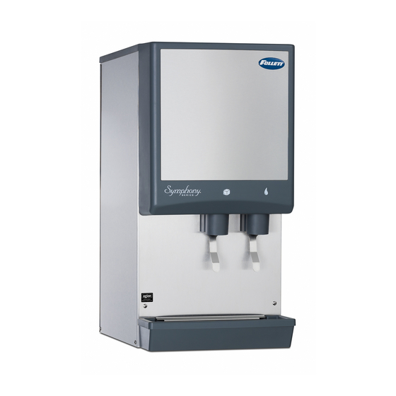
countertop dispenser
Following installation, please forward this manual
12 Series - 220V 60Hz/230V 50Hz
Ice and Water Dispensers
Installation, Operation and Service Manual
C/E12CI400A
countertop dispenser with
SensorSAFE
(shown with legs accessory)
to the appropriate operations person.
801 Church Lane • Easton, PA 18040, USA
(610) 252-7301 • Fax (610) 250-0696 • www.follettice.com
wall mount dispenser (available
™
actuation
C/E12HI400A
with or without drain pan)
00124438R03
Advertisement
Table of Contents
Troubleshooting

Related Manuals for Follett 12 Series


Summary of Contents for Follett 12 Series
- Page 1 12 Series - 220V 60Hz/230V 50Hz Ice and Water Dispensers Order parts online Installation, Operation and Service Manual www.follettice.com C/E12CI400A C/E12CI400A C/E12HI400A countertop dispenser countertop dispenser with wall mount dispenser (available SensorSAFE ™ actuation with or without drain pan) (shown with legs accessory) Following installation, please forward this manual to the appropriate operations person.
-
Page 2: Table Of Contents
Table of contents Welcome to Follett Corporation Important cautions Specifi cations Installation Installing countertop dispensers without legs Installing countertop dispenser with legs accessory Installing wall mount dispensers User information Cleaning and sanitizing procedures Dispenser cleaning Icemaker cleaning and sanitizing Start-up following cleaning Service information Wiring diagram –... -
Page 3: Welcome To Follett Corporation
Welcome to Follett Follett equipment enjoys a well-deserved reputation for excellent performance, long-term reliability and outstanding after-the-sale support. To ensure that this equipment delivers that same degree of service, we ask that you review the installation portion of this manual before beginning to install the unit. Our installation instructions are designed to help you achieve a trouble-free installation. -
Page 4: Specifi Cations
Specifi cations 575mm air exhaust (22.625") 826mm intake (32.5") 3/4" FPT drain 3/8" FPT water inlet intake DRAIN ICE MACHINE MAKE-UP WATER 458mm 407mm (18") power cord 102mm (16") 597mm (4") (23.5") Dispenser front view Dispenser side view Dispenser rear view Electrical 220V 60Hz, 1 phase, 6.5 amps 230V 50Hz, 1 phase, 6.5 amps... -
Page 5: Installation
Installation procedures Before you begin • All dispensers must be installed level in both directions to ensure proper operation. • Service and ventilation clearances: 153mm (6") on right side of dispenser, 153mm (6") at top for ventilation and 305mm (12") at top recommended for service. •... -
Page 6: Installing Countertop Dispenser With Legs Accessory
Fig. 2 – Bottom exiting utilities Fig. 3 – Rear exiting utilities (countertop units) (countertop units) Pipe plug may be moved to back of unit for alternate drain hook up 19mm (3/4") FPT drain 407mm (16") 298mm (11.7" ) Poly tubing and elbow may be 10mm (3/8") push-in 39mm removed for alternate water inlet... -
Page 7: Installing Wall Mount Dispensers
Installing wall mount dispensers Notes: No drain pan is provided since the dispenser is intended to be installed above a sink. (Contact Follett if a drain pan is desired.) SensorSAFE actuation is standard. (Contact Follett if lever actuation is desired. A deeper cabinet will be needed.) Recommended minimum counter depth and mounting height shown on Fig. - Page 8 Installing wall mount dispensers Fig. 6 – Wall mounting dimensions outline of dispenser Caution: Do NOT rest dispenser weight on 331mm (13") bottom of support bracket. 12mm (.437") 166mm (6.5") 204mm (8") 356mm (14") 178mm (7") Wall mount side view Fig.
- Page 9 Fig. 8 – Wall mount unit bottom panel assembly Fig. 9 – Wall mount bottom view support bracket bottom panel 19mm (3/4") 10mm (3/8") push-in FPT drain water inlet screw Fig. 10 – Front view of wall mount bracket – utility location Side view of utilities exiting wall water and 19mm (3/4")
-
Page 10: User Information
User information How the dispenser works Follett’s 12 series automatic-load ice and water dispensers are equipped with Follett’s 181kg (400 lb)/day icemaker. In the continuous icemaking process, water freezes to the inside wall of the evaporator. A rotating stainless steel auger carries the ice to the top of the evaporator where it is compressed and extruded through an outlet port. -
Page 11: Icemaker Cleaning And Sanitizing
5. Wipe lid, wheel, baffle, inside of storage area and dispense chute with damp cloth wrung out in Solution A. 6. Rinse all above items with damp cloth and wring out in clear water. Note: To avoid possible damage to motor assembly, use a damp cloth only to clean storage hopper. Do not allow water to run through center hole in bottom of hopper. -
Page 12: Start-Up Following Cleaning
6. Following manufacturer’s instructions, prepare one gallon (3.8L) of Follett SafeCLEAN Ice Machine Cleaner (one 7 oz packet) or equivalent. Solution temperature must be at least 120 F (48.9 C). Warning: Most ice machine cleaners contain citric or phosphoric acid that can cause skin irritation. Read caution label on product and follow instructions carefully. -
Page 13: Service Information
Access to electrical box and control board electrical box The 12 series electrical box has been designed to slide out for easy access to the control board and more convenient troubleshooting. 1. Remove top and front panels of dispenser (for panel removal instructions). -
Page 14: Wiring Diagram - Lever Model
Wiring diagram – lever model... -
Page 15: Wiring Diagram - Sensorsafe Model
Wiring diagram – SensorSAFE model NEUTRAL... -
Page 16: Icemaker Operational And Diagnostic Sequences
Icemaker operational and diagnostic sequences The wiring diagrams that follow illustrate the circuitry of Follett icemakers used with 12 series ice dispensers. Both normal operation (Stages 1 – 6) and non-normal diagnostic sequences showing torque-out (Stages 7 – 10) for use in troubleshooting are shown. - Page 17 Normal operation – Stage 2 The water sensor verifi es water in the fl oat reservoir. The water OK LED (WTR) comes on. At the same time, the gearmotor, compressor and condenser fan motor come on, lighting the drive LED (DR) and compressor LED (C). The gearmotor is started through a current style relay that is pulled in by the initial high current draw of the run winding.
- Page 18 Normal operation – Stage 4 Once the ice level control opens, the B-E LED goes out. After a 10 second delay the compressor LED (C), compressor and fan motor go off. (Should the ice level control not remain open for 10 seconds, the icemaker will continue to run.) The gearmotor continues to run and the DR LED remains on for 60 seconds.
- Page 19 Normal operation – Stage 6 When the dwell time of 20 minutes has expired, the B-T LED goes off. The icemaker goes through the normal start-up sequence when the bin level control signals the control board for ice. The WTR LED will remain on as long as the water sensor in the fl oat reservoir senses water.
- Page 20 Diagnostic sequence – Stage 8 If the restart is successful the 20M LED goes off, the 60 minute timer LED (60M) comes on. The 60M LED will remains on for 60 minutes from restart. A lighted 60M LED indicates the icemaker has experienced an over-torque condition.
-
Page 21: Refrigeration Cycle Diagram
Diagnostic sequence – Stage 10 If the water level in the fl oat reservoir drops to an unacceptable level, the WTR LED goes out, shutting the icemaker off. Also, the BT LED comes on, preventing the icemaker from restarting for twenty minutes. If water is restored, the WTR LED comes back on and fl ashes to alert the technician that water to icemaker has been lost. -
Page 22: Icemaker Capacity Chart
Refrigeration pressure data Air-cooled icemaker capacity/24 hrs. Ambient Air Temperature ˚F/˚C lbs. lbs. lbs. lbs. lbs. Air-cooled Icemaker Refrigeration Pressure Discharge Pressure/Suction Pressure Ambient air temperature C Ambient air temperature F 12/1.6 16.9/2.1 16.3/2.5 174/23 245/31 237/37 12/1.6 16.8/2.1 22.5/2.6 174/23 244/30 326/38... -
Page 23: Refrigeration System Data And Requirements
Refrigeration system Important: All service on refrigeration system must be performed in accordance with all federal, state and local laws that pertain to the use of refrigerants. It is the responsibility of the technician to ensure that these requirements are met. Icemaker charge specifi cations Model Charge... -
Page 24: Dispenser Troubleshooting - Lever Models
Ice capacity test Icemaker production capacity can only be determined by weighing ice produced in a specifi c time period. 1. Remove top panel and hopper lid of unit. 2. Weigh and record weight of container used to catch ice. 3. -
Page 25: Dispenser Troubleshooting - Sensorsafe Models
Terminals: LI (incoming power, hot), L2 (neutral terminals), WTR (power terminal for water solenoid), WM (power terminal for wheelmotor), CLN (terminals for clean cycle switch). Note: SOL terminal not used in 12 series dispensers. Lens/sensor troubleshooting 1. Turn dispenser power switch off and remove slash panel. -
Page 26: Icemaker Troubleshooting
Icemaker troubleshooting chart • Flashing water LED at any time indicates that water signal to board had been lost for more than one second. • Ten-second delay: There is a 10 second delay in reaction to loss of water (WTR) or bin (B-E) signals. If signals are not lost for more than 10 seconds, no reaction will occur. - Page 27 Icemaker troubleshooting chart Problem Indicators/possible cause Corrective action 6. Icemaker runs 1. Kink in ice transport tube. 1. Eliminate kink and check that tube for short period 2. Bin level control remains in closed routing complies with Follett icemaker of time and shuts position.
-
Page 28: Disassembly And Replacement Instructions
Disassembly and replacement instructions Dispense chute removal stud assembly 1. Remove top cover (see page 30). 2. Remove stainless front cover (see page 30) agitator 3. Slide plastic dispense chute cover up and out to remove. 4. Remove four (4) push fasteners holding dispense tube in place and remove tube. - Page 29 Evaporator disassembly Note: The upper bearing, lower bearing and auger assemblies must be replaced as assemblies. The bottom and top bearing assemblies cannot be fi eld assembled to factory specifi cations. 1. Disconnect power to icemaker. 2. Shut off water to icemaker. 3.
-
Page 30: Panel Removal
Panel removal top cover front cover screw Front cover: Remove 2 screws. Lift cover up and Top cover: Lift cover up and off Velcro strips. forward to unhook from keyhole slots and clear tabs on bottom of cover. back panel screw RH side panel LH side... -
Page 31: Thermostat And Ice Transport Tube Replacement
Thermostat and ice transport tube replacement ice tube retainer ice tube gasket Ice transport tube: tube may Top View extend a maximum of 7mm 77mm (1/4") into ice bin (3") capillary 51mm tube (2") bracket 13mm (.50") Thermostat: hand bend cap tube end as shown Ice transport tube replacement 1. -
Page 32: Replacement Parts
Parts Dispenser exterior DRAIN ICE MACHINE MAKE-UP WATER Part # Description Reference # 502932 Cover, front 502819 Cover, dispense assembly 502400 Cover, dispense assembly, ice 502402 Louver, intake 502412 Grille, drain pan Not shown 502883 Drain pan, plastic 502410 Drain pan assembly (includes base, pan and grill) 502394 Panel, rear 502399... -
Page 33: Wheelmotor And Drive System
Wheelmotor and drive system storage hopper interlock switch Top view Part # Description Reference # 502933 Motor, wheel – 220V 60 Hz/230V 50Hz (includes 502537) 502384 Drive shaft extension 502385 Coupling (includes key) 501273 Key, 1/8" sq x 1-1/4" lg 502414 Baffle, ice (securing hardware included) 502387... - Page 34 Dispense chute and splash panel — lever model water solenoid assembly Part # Description Reference # 502513 Chute assembly, ice 502249 Chute, water 502247 Bracket, dispense chute (includes four (4) 502057 fasteners) 502417 Lever 501100 Thumbscrew 502409 Switch, dispense, water/ice (includes nut, boot and spacer) 502418 Boot, dispense switch button (mounts over the dispense button) 502057...
- Page 35 Dispense chute and splash panel – SensorSAFE model Part # Description Reference # 502513 Chute assembly, ice 502249 Chute, water 502247 Bracket, dispense chute (includes four (4) 502057 fasteners) 00122978 Sensor (includes 502690 and 203611) 501100 Thumbscrew 502819 Cover, dispense chute 502934 Solenoid assembly (includes solenoid, fi ttings, tube &...
-
Page 36: Water Fi Lter Kits And Cartridges
Icemaker components Part # Description Reference # 501581 Drier 501187 Coil, condenser 502116 Water sensor 500504 Float valve & reservoir 502078 Fitting, plastic, fl oat valve (includes sleeve & stem) Not shown 502221 Compression nozzle, single drain Evaporator (see page 39 for detailed drawing) 501820 Shroud, condenser coil Not shown... - Page 37 Icemaker components Right side view Rear view OPERATE UNIT WITH PANELS REMOVED. Left side view Top view (lower section)
-
Page 38: Electrical Components
Electrical components Side View Top View Note: located behind front splash panel Part # Description Reference # 502938 Board, control circuit – 220V 60Hz/230V 50Hz 502915 Control board, SensorSAFE models – 220V 60Hz/230V 50Hz 502116 Water sensor 502209 Switch, on/off, compressor, bin signal 502409 Switch, cleaning, SensorSAFE models 500514... - Page 39 Evaporator replacement parts Part # Description Reference # 502735 Coupling, vee band, includes nut 502736 Bearing assembly, top 502110 Loop, ice compression, beveled 502737 Auger 502725 Evaporator (includes insulation jacket, 502740) 500496 O ring, bearing housing 502738 Bearing assembly, bottom (includes O rings and condensate shield) 501063 O ring, mounting base...
- Page 40 801 Church Lane • Easton, PA 18040, USA 00124438R03 (610) 252-7301 • Fax (610) 250-0696 • www.follettice.com 08/07...
Need help?
Do you have a question about the 12 Series and is the answer not in the manual?
Questions and answers