Follett 12CI400A-LI Installation, Operation And Service Manual
Symphony 12 series ice and water dispensers
Hide thumbs
Also See for 12CI400A-LI:
- Installation, operation and service manual (44 pages) ,
- Installation, operation and service manual (44 pages)
Table of Contents
Advertisement
Order parts online
www.follettice.com
12CI400A-L
countertop dispenser
Following installation, please forward this manual
1
Ice and Water Dispensers
Installation, Operation and Service Manual
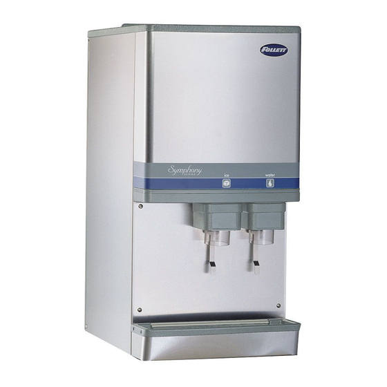
12CI400A-LI
countertop, ice-only
dispenser
12CI400A-S
countertop dispenser with
SensorSAFE infrared dispensing
(shown with legs accessory)
to the appropriate operations person.
801 Church Lane • Easton, PA 18040, USA
Toll free (877) 612-5086 • +1 (610) 252-7301
www.follettice.com
12CI400A-SI countertop, ice-only
dispenser with SensorSAFE
infrared dispensing
12 Series
™
12HI400A-S
wall mount dispenser
(available with or without
drain pan)
12CI400A • 12HI400A
208595R21
Advertisement
Table of Contents
Troubleshooting

Related Manuals for Follett 12CI400A-LI


Summary of Contents for Follett 12CI400A-LI
- Page 1 12 Series Ice and Water Dispensers Installation, Operation and Service Manual Order parts online www.follettice.com 12CI400A-LI 12CI400A-SI countertop, ice-only countertop, ice-only dispenser with SensorSAFE ™ dispenser infrared dispensing 12CI400A-L 12HI400A-S 12CI400A-S countertop dispenser wall mount dispenser countertop dispenser with (available with or without...
-
Page 2: Table Of Contents
Welcome to Follett........ -
Page 3: Welcome To Follett
Before you begin After uncrating and removing all packing material, inspect the equipment for concealed shipping damage. If damage is found, notify the shipper immediately and contact Follett Corporation so that we can help in the filing of a claim, if necessary. -
Page 4: Specifications
Specifications 22.625" (575 mm) air exhaust 32" (826 mm) 3/4" FPT drain 3/8" FPT water inlet intake 18" 16" 4" (102 mm) (458 mm) power cord (407 mm) 23.5" (597 mm) Front View Side View Rear View Electrical § 115 V, 60 Hz, 1 phase, 13.0A §... -
Page 5: Installation
Installation Before you begin § All dispensers must be installed level in both directions to ensure proper operation. § Service and ventilation clearances: 6" (153 mm) on right side of dispenser, 6" (153 mm) at top for ventilation and 12" (305 mm) at top recommended for service. §... -
Page 6: Installing Countertop Dispensers With Legs Accessory
Fig. 3 – Rear exiting utilities Fig. 2 – Bottom exiting utilities (countertop units) (countertop units) Move pipe plug to back of unit 3/4" FPT drain 16" (407 mm) 11.7" (298 mm) Remove poly tubing and 3/8" OD push-in water inlet fitting for water inlet 8.1"... -
Page 7: Installing Wall Mount Dispensers
Installing wall mount dispensers Notes: § No drain pan is provided since the dispenser is intended to be installed above a sink. (Contact Follett if a drain pan is desired.) § SensorSAFE infrared dispensing is standard. (Contact Follett if lever actuation is desired. A deeper cabinet will be needed.) -
Page 8: Installing Wall Mount Dispensers
Installing wall mount dispensers Fig. 6 – Wall mounting dimensions outline of dispenser Caution: Do NOT rest dispenser weight on 13" (331mm) bottom of support bracket. 6.5" 8" (166mm) (204mm) .437 14" (356mm) 7" (178mm) 3" (77mm) 1.4" (36mm) 10" 3"... - Page 9 Fig. 8 – Wall mount unit bottom panel assembly Fig. 9 – Wall mount bottom view support bracket 3/4" FPT drain bottom panel 3/8" OD push-in screw water inlet Fig. 10 – Front view of wall mount bracket, utility location water and 3/8"...
-
Page 10: User Information
User information How the dispenser works Follett’s 12 series automatic-load ice and water dispensers are equipped with Follett’s 400 lb (181kg)/day ice machine. In the continuous icemaking process, water freezes to the inside wall of the evaporator. A rotating stainless steel auger carries the ice to the top of the evaporator where it is compressed and extruded through an outlet port. -
Page 11: Cleaning/Descaling And Sanitizing
Cleaning of the condenser can usually be performed by facility personnel. Cleaning/descaling and sanitizing of the ice machine system should be performed by your facility’s trained maintenance staff or a Follett authorized service agent. Regardless of who performs the cleaning, it is the operator’s responsibility to see that this cleaning is performed according to the schedule below. -
Page 12: Semi-Annually
§ Do not use solvents, abrasive cleaners, metal scrapers or sharp objects to clean any part of the dispenser. Solution A: Following manufacturer’s instructions, mix cleaning solution of 1 gal. (3.8L) 120 F (49 C) water and 7 oz. (198 g) (one 7 oz. packet) of Follett SafeCLEAN™ ice machine cleaner/descaler (P/N 00132001). - Page 13 20. Continue to make ice with Solution B for 20 minutes. 21. Turn power to ice machine OFF. 22. Disconnect ice transport tube from evaporator outlet port. Rinse ice compression nozzle and drain lines in clean water and reinstall on evaporator outlet. Reconnect ice transport tube to ice compression nozzle.
-
Page 14: Service
The icemaking process The Follett ice machine uses a stainless steel jacketed evaporator and operates on a continuous freezing cycle. Water is supplied to the evaporator from the water reservoir where the water level is controlled by a float valve. -
Page 15: Wiring Diagram - Models With Lever Dispensing
Wiring diagram – models with lever dispensing 12CI400A • 12HI400A... -
Page 16: Wiring Diagram - Models With Sensorsafe Infrared Dispensing
Wiring diagram – models with SensorSAFE infrared dispensing NEUTRAL 12CI400A • 12HI400A... -
Page 17: Ice Machine Operational And Diagnostic Sequences
Ice machine operational and diagnostic sequences The wiring diagrams that follow illustrate the circuitry of Follett ice machines used with 12 series ice dispensers. Both normal operation (stages 1 - 6) and non-normal diagnostic sequences showing torque-out (stages 7 - 10) for use in troubleshooting are shown. -
Page 18: Normal Operation - Stage 2
Normal operation – Stage 2 The water sensor verifies water in the float reservoir. The water OK LED (WTR) comes on. At the same time, the gearmotor, compressor and condenser fan motor come on, lighting the drive LED (DR) and compressor LED (C). - Page 19 Normal operation – Stage 4 Once the ice level control opens, the B-E LED goes out. After a 10 second delay the compressor LED (C), compressor and fan motor go off. (Should the ice level control not remain open for 10 seconds, the ice machine will continue to run.) The gearmotor continues to run and the DR LED remains lighted for 60 seconds.
- Page 20 Normal operation – Stage 6 When the dwell time of 20 minutes has expired, the B-T LED goes off. The ice machine goes through the normal start-up sequence when the bin level control signals the control board for ice. The WTR LED will remain on as long as the water sensor in the float reservoir senses water.
- Page 21 Diagnostic sequence – Stage 8 If the restart is successful the 20M LED goes off, the 60 minute timer LED (60M) comes on. The 60M LED remains on for 60 minutes from restart. A lighted 60M LED indicates that the ice machine has experienced an over-torque condition.
-
Page 22: Refrigeration Cycle
Diagnostic sequence – Stage 10 If the water level in the float reservoir drops to an unacceptable level, the WTR LED goes out, shutting the ice machine off. Also, the BT LED comes on, preventing the ice machine from restarting for twenty minutes. If water is restored, the WTR LED comes back on and flashes to alert the technician that water to ice machine has been lost. -
Page 23: Refrigeration Pressure Data
Refrigeration pressure data Air-cooled icemaker capacity/24 hrs. Ambient Air Temperature ˚F/˚C lbs. lbs. lbs. lbs. lbs. Air-cooled Icemaker Refrigeration Pressure Discharge Pressure/Suction Pressure Ambient air temperature ˚F/˚C 60/16 80/27 ˚F/˚C 100/38 174/23 245/31 237/37 50/10 174/23 244/30 326/38 70/21 90/32 190/25 265/32 347/40... -
Page 24: Refrigeration System
Refrigerant replacement requirements 1. Non-contaminated refrigerant removed from any Follett refrigeration system can be recycled and returned to the same system after completing repairs. Recycled refrigerant must be stored in a clean, approved storage container. If additional refrigerant is required, virgin or reclaimed refrigerant that meets ARI standard 700-88 must be used. -
Page 25: Dispenser Troubleshooting
Ice capacity test Ice machine production capacity can only be determined by weighing ice produced in a specific time period. 1. Remove top panel and hopper lid of unit. 2. Weigh and record weight of container used to catch ice. 3. -
Page 26: Troubleshooting The Dispenser - Models With Sensorsafe Infrared Dispensing
SensorSAFE model troubleshooting guide SensorSAFE Board LED Status ICE/ Problem Action Corrective Action Does not Check Check circuit breakers and power switch. dispense ice LEDs on the Restore power or replace defective switch. and/or water. SensorSAFE Press clean switch on lower left side of electrical control board. -
Page 27: Ice Machine Troubleshooting Chart
2. Remove obstruction. Poor quality ice. 3. Mineral coated evaporator. 3. Clean evaporator. 4. Improper exhaust air provisions. 4. Provide proper exhaust air provisions per Follett installation manual. 5. Faulty expansion valve. 5. Replace expansion valve. 6. Low refrigerant charge. -
Page 28: Ice Machine Troubleshooting Chart
3. Clogged or dirty air filter or condenser coil. 3. Clean or replace filter, clean condenser coil. motor run. 4. Improper ventilation. 4. Provide inlet and exhaust air provisions per Follett ice machine installation manual. 5. Defective compressor. 5. Replace compressor. -
Page 29: Disassembly And Replacement Instructions
Disassembly and replacement instructions Dispense chute removal threaded rod 1. Remove top cover (see page 31). 2. Remove stainless front cover (see page 31). agitator 3. Slide plastic dispense chute cover up and out to remove. 4. Remove four (4) push fasteners holding dispense tube in place and remove tube. - Page 30 Evaporator disassembly Note: The upper bearing, lower bearing and auger assemblies must be replaced as assemblies. The bottom and top bearing assemblies cannot be field assembled to factory specifications. 1. Disconnect power to ice machine. 2. Shut off water to ice machine. 3.
-
Page 31: Panel Removal
Panel removal top cover Front cover: Pull bottom of cover, then lift cover up and Top cover: Lift cover up and off Velcro strips. forward to unhook from keyhole slots. back panel screw RH side panel LH side panel screw louver splash panel panel... -
Page 32: Thermostat And Ice Transport Tube Replacement
Thermostat and ice transport tube replacement ice tube retainer ice tube gasket Ice transport tube: tube may extend a maximum of 1/4" (6 mm) into ice bin 3" (76 mm) capillary tube 2" (51 mm) bracket .50 TYP Thermostat: hand bend cap tube end as shown Top view Ice transport tube replacement... -
Page 33: Replacement Parts
Replacement parts Dispenser exterior Reference # Description Part # Cover, front (serial numbers below D61292) 502818 Cover, front (serial numbers D61292 and above) 00981068 Louver, intake, plastic 00967117 Not shown Grille, drain pan 01051614 Drain pan, plastic 00967059 Drain pan assembly (includes base, pan and grille) 502410 Panel, rear 502394... -
Page 34: Wheelmotor And Drive System
Wheelmotor and drive system storage hopper interlock switch Top view Reference # Description Part # Motor, wheel, long shaft (includes 502537) 502580 Drive shaft extension 502384 Coupling (includes key) (short shaft motor only) 502385 Key, 1/8" sq x 1-1/4 lg 501273 Baffle, ice (securing hardware, part# 00167973, included) 502414... -
Page 35: Dispense Chute And Splash Panel (Models With Lever Dispensing)
Dispense chute and splash panel (models with lever dispensing) — Serial Number D61292 and above (located behind water reservoir) Reference # Description Part # Chute, ice or water (with Agion antimicrobial product protection 00967760 ® Support, water tube 00960682 Lever 00976845 Boot, dispense switch button 502418... -
Page 36: Dispense Chute And Splash Panel (Models With Sensorsafe Infrared Dispensing)
Dispense chute and splash panel (models with SensorSAFE infrared dispensing) — Serial Number D61292 and above Reference # Description Part # Chute, ice or water (with Agion) 00967760 Sensor (includes lens and Ty-rap*) 00122978 Support, water tube 00960682 Screw, panel 00982421 Fitting, bulkhead (with nut) 00976787... -
Page 37: Dispense Chute And Splash Panel (Models With Lever Dispensing)
Dispense chute and splash panel (models with lever dispensing) — Serial Numbers below D61292 water solenoid assembly Reference # Description Part # Chute, ice, with bracket and fasteners (with Agion) 00981225 Chute assembly (clear), ice 502513 Chute, water, with bracket and fasteners (with Agion) 00981233 Chute (clear), water 502249... -
Page 38: Dispense Chute And Splash Panel
Dispense chute and splash panel (models with SensorSAFE infrared dispensing — Serial Numbers below D61292 Reference # Description Part # Chute, ice, with bracket and fasteners (with Agion) 00981225 Chute assembly (clear), ice 502513 Chute, water, with bracket and fasteners (with Agion) 00981233 Chute (clear), water 502249... -
Page 39: Ice Machine Components
Ice machine components Right side view Rear view OPERATE UNIT WITH PANELS REMOVED. Top view (lower section) Left side view 12CI400A • 12HI400A... -
Page 40: Ice Machine Components
Ice machine components Reference # Description Part # Drier 502724 Coil, condenser 501187 Water sensor 502116 Float valve & reservoir 500504 Not shown Elbow, 1/4", push-in 00121699 Not shown Adapter, female thread to 1/4" push-in 00998716 Not shown Fitting, plastic, float valve (includes sleeve & stem) 502078 Compression nozzle, single drain 502221... -
Page 41: Electrical Components
Electrical components Side view Top view Reference # Description Part # Capacitor, start, compressor, 115 V, 60 Hz 502780 Relay, start, compressor, 115 V, 60 Hz 501588 Board, control circuit, 115 V, 60 Hz 502331 Water sensor 502116 Switch, on/off, compressor 502392 Switch, rocker, power 502209... -
Page 42: Evaporator Replacement Parts
Evaporator replacement parts Reference # Description Part # Coupling, vee band, includes 502735 Bearing assembly, top 502736 Loop, ice compression, 502110 beveled Auger 502737 Evaporator (includes 502725 insulation jacket, 502740) O ring, bearing housing 500496 Bearing assembly, bottom 502738 (includes O rings and condensate shield) O ring, mounting base 501063... -
Page 43: Water Treatment Accessories For Symphony Ice And Water Dispensers
Description Part # Standard capacity filter system Not shown Follett QC4-FL4S water filter system (includes FL4S primary cartridge and head, coarse 00130229 pre-filter and head, pressure gauge, flushing valve; assembled and installed on mounting bracket), one per ice machine Not shown... - Page 44 SafeCLEAN, SensorSAFE and Symphony are trademarks of Follett Corporation. Follett and RIDE are registered trademarks of Follett Corporation, registered in US. 801 Church Lane • Easton, PA 18040, USA 208595R21 Toll free (877) 612-5086 • +1 (610) 252-7301 © Follett Corporation 7/14...
Need help?
Do you have a question about the 12CI400A-LI and is the answer not in the manual?
Questions and answers