
Related Manuals for Roban B-25J Mitchell


Summary of Contents for Roban B-25J Mitchell
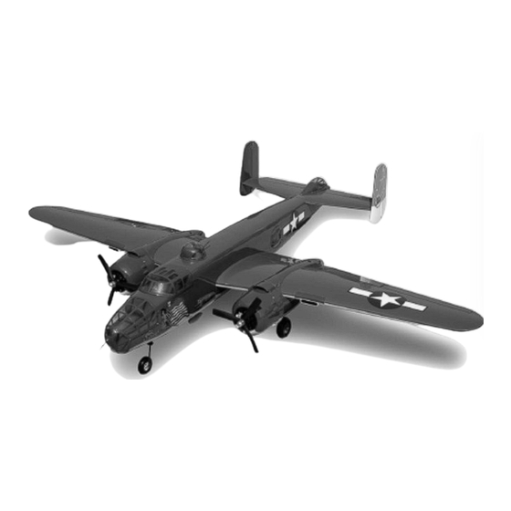
- Page 1 B-25J Mitchell RC Airplane KIT Exclusively for www.scaleflying.com Manual FIXED WING RC AIRCRAFT ...
- Page 2 Super Scale RC Airplane Manual – B-25J Release 1.0 - Jan 2015 Roban Limited Zhengyacun Industrial Zone, Venture Cross Rd. Jiaolian, Wanjiang City District of Dongguan, 523046 Dongguan County (GD) - PRC Copyright@2015 - Roban Limited – All rights reserved...
-
Page 3: Specifications
Please read this user manual carefully, it contains instructions for the correct assembly of the model. Please refer to the web site www.robanmodel.com for updates and other important information. Thank you for your purchase, and have a great time with your Airplane! Roban Limited Copyright@2015 - Roban Limited – All rights reserved... -
Page 4: Important Notes
*Lack of care with assembly or maintenance can result in an unreliable and dangerous model. *Neither Roban Limited nor its agents have any control over the assembly, maintenance and use of this product. Therefore, no responsibility can be traced back to the manufacturer. You hereby agree to release Roban Limited from any responsibility or liability arising from the use of this product. - Page 5 30 – Screw M3x22 x2 31 – Washer M3x8 x13 32 – Washer M3x10 x8 33 – Screw M4x45 x2 34 – Screw M3x22 x2 35 – Screw M3x18 x4 36 – Screw M3x14 x8 Copyright@2015 - Roban Limited – All rights reserved...
- Page 6 66 – Servo mount x4 67 – Servo mount x2 68 – Engine cowl mount x8 69 – Front wheel mount 70 – Front wheel rod guide 71 – RHS Firewall 72 – LHS Firewall Copyright@2015 - Roban Limited – All rights reserved...
-
Page 7: Additional Components Required
*Cyanoacrylate adhesive *7 40g metal geared servos *Epoxy glue 30 min. *2 flat type wing mount metal geared servos *Soldering equipment (for motor wiring) *6 channel radio control system on 2.4 GHz Copyright@2015 - Roban Limited – All rights reserved... - Page 8 Also make sure the flap and aileron do not bind against each other. Copyright@2015 - Roban Limited – All rights reserved...
- Page 9 After the CA has fully cured, gently pull on the wing and aileron to make sure the hinges are secure. If not, re-glue the hinges. To break in the hinges, you will need to flex the aileron up and down a number of times. Copyright@2015 - Roban Limited – All rights reserved...
- Page 10 Hinging the flaps follows the same procedure as the ailerons, except you will need to apply 30-minute epoxy to the torque rods that enter the flaps. STEP 2 AILERON AND OUTER FLAP SERVO INSTALLATION (REPEAT 4 TIMES) 1. Remove the servo cover from the wing. Copyright@2015 - Roban Limited – All rights reserved...
- Page 11 CA into each of the holes to harden the surrounding wood to provide a stronger surface for the screws to bite into. Mount the servo to the blocks using the hardware provided with the servo. Copyright@2015 - Roban Limited – All rights reserved...
-
Page 12: Routing The Wires
Mount 4 ball links (1) onto one end of 4 pushrods (6). Mount the uniballs (2) onto all four servo horns. Thread the clevis (28) onto the other end of the pushrods. Thread the bearing holder (26) onto the control horn (23). Attach the ball link to the servo horn. Copyright@2015 - Roban Limited – All rights reserved... - Page 13 Then mount an uniball (2) onto the servo horn. Mount another uniball on the T-Junction using Loctite. Thread 2 ball links (1) onto the pushrod (7) and connect the servo horn with the T-Junction. Copyright@2015 - Roban Limited – All rights reserved...
- Page 14 1. Install Nacelle Framework and gear doors Align both motor and landing gear mounts inside the nacelle and glue them in with 30 min. epoxy glue. The install the landing gear doors as shown. Copyright@2015 - Roban Limited – All rights reserved...
- Page 15 2. Install retract and landing gear Copyright@2015 - Roban Limited – All rights reserved...
- Page 16 Copyright@2015 - Roban Limited – All rights reserved...
- Page 17 3. Install front retract steering servo and gear door Follow the steps as shown below. Copyright@2015 - Roban Limited – All rights reserved...
- Page 18 Copyright@2015 - Roban Limited – All rights reserved...
- Page 19 Copyright@2015 - Roban Limited – All rights reserved...
- Page 20 Copyright@2015 - Roban Limited – All rights reserved...
- Page 21 Then mount the motor holders onto the nacelle’s firewalls with screws (32) and washers (33) using loctite. Blind nuts are premounted on the other side of the firewall. Copyright@2015 - Roban Limited – All rights reserved...
- Page 22 3. Install engine cowl After installing the engine cowl holders (68) onto the firewall, holes need to be drilled into the cowl so that the cowl can be secured with screws (42). Copyright@2015 - Roban Limited – All rights reserved...
- Page 23 Finally mount the cowl using the screws (42) onto the nacelle. Copyright@2015 - Roban Limited – All rights reserved...
-
Page 24: Step 7 Engine Nacelle Installation
Attach the engine nacelle to the wing using two screws (35) and washers (31) using loctite. The front section of the nacelle has preinstalled dowels, these must engage before the screws are used to tighten the nacelle to the wing. Copyright@2015 - Roban Limited – All rights reserved... -
Page 25: Step 8 Wing Installation
Installation, Steps 1 through 5, using servo holder plate (16) and mounting blocks (56) instead). Use a 180 degree servo arm and remove the excess arm using side cutters. Simply follow those steps to mount the rudder servo to the rudder servo cover. Copyright@2015 - Roban Limited – All rights reserved... - Page 26 This provides a tunnel allowing the glue used to secure the hinges to fully penetrate the hinge. Note: Drill the holes in the hinge slots for the elevators and stabilizer at this time as well. Copyright@2015 - Roban Limited – All rights reserved...
- Page 27 After the CA has fully cured, gently pull on the rudder and fin to make sure the hinges are secure. If not, re-glue the hinges. To break in the hinges, you will need to flex the rudder back and forth a number of times. Copyright@2015 - Roban Limited – All rights reserved...
-
Page 28: Step 10 Rudder And Elevator Servo Installation
Then mount an uniball (2) onto the servo horn. Mount another uniball on the T-Junction using Loctite. Thread 2 ball links (1) onto the pushrod (7) and connect the servo horn with the T-Junction. Copyright@2015 - Roban Limited – All rights reserved... - Page 29 Mark the location for the mounting screw on the rudder with a pencil. Drill a 3mm hole and mount the control rod with screw (24) and washer (21) onto the rudders using Loctite. Copyright@2015 - Roban Limited – All rights reserved...
-
Page 30: Step 11 Tail Section Installation
Make sure to secure all connections so they will not become unplugged inside the fuselage. 2. Secure stabilizer Secure the stabilizer using a hex driver, two socket head screws (34) and washers (31) using loctite. Copyright@2015 - Roban Limited – All rights reserved... - Page 31 STEP 12 SCALE ACCESSORIES 1. Bombardiers cockpit Follow the steps as shown below. Copyright@2015 - Roban Limited – All rights reserved...
- Page 32 Copyright@2015 - Roban Limited – All rights reserved...
- Page 33 2. Cockpit Follow the steps as shown below. Copyright@2015 - Roban Limited – All rights reserved...
- Page 34 Copyright@2015 - Roban Limited – All rights reserved...
- Page 35 Copyright@2015 - Roban Limited – All rights reserved...
- Page 36 Copyright@2015 - Roban Limited – All rights reserved...
- Page 37 3. Top gunner Follow the steps as shown below. Copyright@2015 - Roban Limited – All rights reserved...
- Page 38 4. Tail gunner Follow the steps as shown below. Copyright@2015 - Roban Limited – All rights reserved...
- Page 39 Copyright@2015 - Roban Limited – All rights reserved...
-
Page 40: Side Windows
5. Side windows Follow the steps as shown below. Copyright@2015 - Roban Limited – All rights reserved... - Page 41 6. Bomb bay Follow the steps as shown below. Copyright@2015 - Roban Limited – All rights reserved...
- Page 42 Copyright@2015 - Roban Limited – All rights reserved...
- Page 43 Copyright@2015 - Roban Limited – All rights reserved...
- Page 44 Copyright@2015 - Roban Limited – All rights reserved...
-
Page 45: Step 13 Center Of Gravity
Moving it closer to center will decrease throw, and away from center will increase throw. Work with a combination of the two to achieve the closest or exact control throws listed. 2. Control throws Elevator Low Rate 7 degrees, 3/8‐inch or 8.5mm up/down Elevator High Rate 13 degrees, 5/8‐inch or 16mm up/down Note: Elevator throw is measured at inboard end of elevator. Rudder Low Rate Copyright@2015 - Roban Limited – All rights reserved... -
Page 46: Step 15 Range Test Your Radio
Once you have finished this be sure and take a minute to change the batteries and take one last look at the airframe to be sure all screws and control linkages are Copyright@2015 - Roban Limited – All rights reserved... -
Page 47: National Model Aircraft Safety Code
8. I will not operate model aircraft carrying pyrotechnic devices which explode burn, or propel a projectile of any kind. Exceptions include Free Flight fuses or devices that burn producing smoke and are securely attached to Copyright@2015 - Roban Limited – All rights reserved... - Page 48 No model aircraft shall be equipped with devices which allow it to be flown to a selected location which is beyond the visual range of the pilot. Copyright@2015 - Roban Limited – All rights reserved...
- Page 49 NOTES: Copyright@2015 - Roban Limited – All rights reserved...
- Page 50 Copyright@2015 - Roban Limited – All rights reserved...
Need help?
Do you have a question about the B-25J Mitchell and is the answer not in the manual?
Questions and answers