Roban BO 105 Instruction Manual
Scale fuselage 500 size
Hide thumbs
Also See for BO 105:
- Instruction manual (13 pages) ,
- Instruction manual (16 pages) ,
- Instruction manual (87 pages)
Advertisement
Quick Links
Instruction manual
Scale Fuselage BO 105
500 size
1. INTRODUCTION
Thank you for buying Roban Model products. The 600 size MD500D/E scale fuselage is
designed as an easy to use product. Please read the manual carefully before assembling the
model, and follow all precautions and recommendations located within the manual. Be sure
to retain the manual for future reference, routine maintenance and tuning. The scale fuselage
is designed for T-REX 600 Helicopter series use. You can easily put it on your T-REX 600 for new
clothing.
Important Note
Roban Model R/C Helicopters are advanced, high-performance devices, built incorporating the
latest technologies. They are not intended as toys, and improper use can potentially lead to
serious injury, or even fatal accidents. We implore you to read this manual thoroughly before
operating these models. Safety should be your utmost priority - not just your own, but also
that of others and your surroundings when piloting Roban Model products.
Liability Disclaimer:
The manufacturer and the seller cannot accept liability for the operation or misuse of this
product. Roban Model R/C helicopters are intended to be used exclusively by experienced
adults in legally sanctioned flying fields. Once sold, we cannot monitor or control the product's
operation or usage.
Operation Guidelines:
Upon assembly of the scale fuselage, the weight and complexity of the structure will increase.
To mitigate risk of accidents and damages, we advise against attempting 3D flights.
Advertisement

Related Manuals for Roban BO 105


Summary of Contents for Roban BO 105
- Page 1 500 size 1. INTRODUCTION Thank you for buying Roban Model products. The 600 size MD500D/E scale fuselage is designed as an easy to use product. Please read the manual carefully before assembling the model, and follow all precautions and recommendations located within the manual. Be sure to retain the manual for future reference, routine maintenance and tuning.
- Page 2 Skill Requirements: The operation of R/C products necessitates a certain level of skill and familiarity. Any damages or dissatisfaction resulting from accidents, modifications, or operational mishaps are not covered under any warranty. Consequently, such products cannot be returned for repair or if you experience problems during operation or maintenance.
- Page 3 3. CONTENTS OF KIT Please check the contents of the kit prior to installation. CONTENTS Item No. Description Quantity Landing gear struts T-connectors Landing gear skids Rear redirection Wooden holders Screw M2x20 Washer M2 Screw A2x12 Linkage holders Tail skid Set screw M3 Windows Horizontal tail unit...
- Page 4 Screw A2x5 REQUIRED TOOLS / CONSUMABLES Tool No. Tool/Consumable Hobby knife Allen wrench Phillips screwdriver File Side cutters Silicone adhesive Super glue 2K Epoxy glue Fine sandpaper Scissors...
-
Page 5: Installation
4. INSTALLATION 4.1 Insert the landing gear linkage into the fuselage as shown. 4.2 Secure the landing gear with 4 pieces of Screw M3x14 as shown. 4.3 Install the T-connectors as shown. - Page 6 4.4 Mount the skids in the connectors and glue them. 4.5 Mount the step ledge on the skids. 4.6 Remove the tail cover with Screw A2x12.
- Page 7 4.7 Install the tail control and test it first. 4.8 Loosen the screw as shown and pivot the tail. 4.9 Glue the wooden holders.
- Page 8 4.10 Mount the wooden holders on the mechanism as shown. 4.11 Install the mechanism in the fuselage. 4.12 Install the tail as shown.
- Page 9 4.13 Install the tail distancer holders in the tail cover as shown. 4.14 Tighten the opposite side using the nut. 4.15 Screw the mechanism in the fuselage with 4 pieces of Screw M2x12.
- Page 10 4.16 Install the tail skid as shown. 4.17 Secure the tail skid with Set Screw M3 as shown. 4.18 Install the tail cover.
- Page 11 4.19 Install the window panes. 4.20 Install the tail winglets with screw. 4.21 Glue the tail units.
-
Page 12: Spare Part List
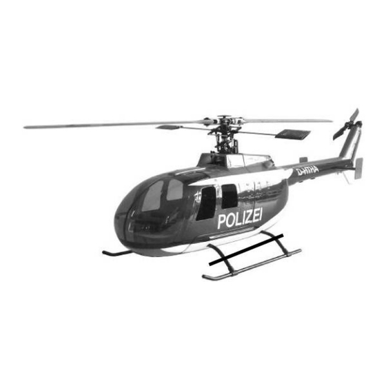
4. SPAREPART LIST 500BO105 前 500 BO-105 HSB-BO500YE BO500PJ001 头含窗 canopy 500 BO-105 500BO105 顶 BO500PJ002 side 窗 windows 500BO105 平 500 BO-105 BO500PJ003 垂尾 tail wings 500 BO-105 500BO105 尾 BO500PJ004 elevated 波箱 tail set 500 BO-105 500BO105 脚 BO500PJ005 landing 架组... - Page 13 4. FULLY ASSEMBLED FUSELAGE Specifications: Lenght: 1005mm Height: 335mm Width: 295mm Weight: 730g Suitable for Align TREX500 Belt and derivatives We wish you a lot of fun with the fuselage! Copyright 2024 – www.robanmodel.com...
Need help?
Do you have a question about the BO 105 and is the answer not in the manual?
Questions and answers