
Related Manuals for Moxa Technologies EtherDevice EDS-G308-T


Summary of Contents for Moxa Technologies EtherDevice EDS-G308-T
- Page 1 EDS-G308 Hardware Installation Guide Moxa EtherDevice Switch Fourth Edition, April 2014 2014 Moxa Inc. All rights reserved. P/N: 1802003082013...
-
Page 2: Package Checklist
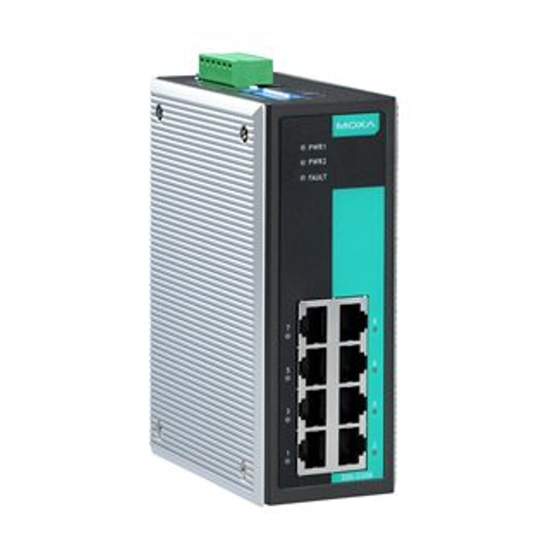
Overview The EDS-G308 series is equipped with 8 Gigabit Ethernet ports and up to 2 fiber optic ports, making it ideal for applications that demand high bandwidth. The EDS-G308 series provides an economical solution for your industrial Gigabit Ethernet connection, and the built-in relay warning function alerts maintainers when power failures or port breaks occur. - Page 3 Panel Layout of EDS-G308/EDS-G308-2SFP 1. Grounding screw 2. Terminal block for power input (PWR1, PWR2) and relay output 3. Power input PWR1 LED 4. Power input PWR2 LED 5. Fault LED 6. TP port’s 10/10/1000 Mbps LED 7. Port number 8.
-
Page 4: Mounting Dimensions
Mounting Dimensions Unit = mm (inch) - 4 -... -
Page 5: Din-Rail Mounting
DIN-Rail Mounting The aluminum DIN-rail attachment plate should already be fixed to the back panel of the EDS when you take it out of the box. If you need to reattach the DIN-rail attachment plate, make sure the stiff metal spring is situated towards the top, as shown in the figures below. -
Page 6: Atex Information
STEP 3: Once the screws are fixed in the wall, insert the four screw heads through the large parts of the keyhole-shaped apertures, and then slide the EDS downwards, as indicated. Tighten the four screws for added stability. ATEX Information 1. - Page 7 You should also pay attention to the following items: • Use separate paths to route wiring for power and devices. If power wiring and device wiring paths must cross, make sure the wires are perpendicular at the intersection point. NOTE: Do not run signal or communications wiring and power wiring in the same wire conduit.
-
Page 8: Wiring The Redundant Power Inputs
Wiring the Redundant Power Inputs The top two contacts and the bottom two contacts of the 6-contact terminal block connector on the EDS’s top panel are used for the EDS’s two AC/ DC inputs. Top and front views of one of the terminal block connectors are shown here. - Page 9 1000BaseT RJ45 Pinouts MDI-X BI_DA+ BI_DB+ BI_DA- BI_DB- BI_DB+ BI_DA+ BI_DC+ BI_DD+ BI_DC- BI_DD- BI_DB- BI_DA- BI_DD+ BI_DC+ BI_DD- BI_DC- RJ45 (8-pin) to RJ45 (8-pin) Straight-Through Cable Wiring RJ45 (8-pin) to RJ45 (8-pin) Cross-Over Cable Wiring 100Base-FX or 1000Base-X Fiber Port The Fiber ports on the EDS-G308 series are SFP type slots, which support both 100Base-FX and 1000Base-X speed fiber transceiver to work properly.
-
Page 10: Redundant Power Inputs
Multi-mode: 100BaseFx 0 to 5 km, 1300 nm (50/125μm, 800MHz*km) 0 to 4 m, 1300 nm (62.5/125μm, 500MHz*km) Single-mode: 100BaseFx 0 to 40 km, 1310 nm (9/125μm, 3.5 PS/(nm*km)) The concept behind the LC port and cable is quite straightforward. Suppose you are connecting devices I and II. -
Page 11: Dip Switch Settings
DIP Switch Settings The default setting for each DIP switch is OFF. The following table explains the effect of setting the DIP switches to the ON positions. DIP Switch Setting Description Enables broadcast storm protection Disables broadcast storm protection ---- Enables jumbo frame function refers to Jumbo Disables jumbo frame function... -
Page 12: Auto Mdi/Mdi-X Connection
TP port’s 10/100 Mbps link is active Data is being transmitted at 10/100 10/100M AMBER Blinking Mbps TP Port’s 10/100 Mbps link is inactive TP port’s 1000 Mbps link is active 1000M GREEN Blinking Data is being transmitted at 1000 Mbps TP Port’s 1000 Mbps link is inactive Auto MDI/MDI-X Connection The Auto MDI/MDI-X function allows users to connect the EDS’s... - Page 13 Interface RJ45 Ports 10/100/1000BaseT(X) auto negotiation speed Fiber Ports 100Base-FX or 1000Base-X SFP slot LED Indicators PWR1, PWR2, FAULT, 10/100M/1000M DIP Switch Port/power break alarm, broadcast storm protection Alarm Contact One relay output with current carrying capacity of 1A @ 24 VDC Optical Fiber: 100 or 1000Base SFP modules Gigabit Ethernet SFP-SX...
- Page 14 Installation DIN-rail, Wall Mounting (optional kit) Environmental Operating 0 to 60°C (32 to 140°F) Temperature -40 to 75°C (-40 to 167°F) for -T models Storage Temperature -40 to 85°C (-40 to 185°F) Ambient Relative 5 to 95% (non-condensing) Humidity Regulatory Approvals Safety UL 508 Hazardous Location...
Need help?
Do you have a question about the EtherDevice EDS-G308-T and is the answer not in the manual?
Questions and answers