Moxa Technologies EtherDevice Switch EDS-G205 Hardware Installation Manual
Hide thumbs
Also See for EtherDevice Switch EDS-G205:
- Manual (84 pages) ,
- Hardware installation manual (14 pages) ,
- Hardware installation manual (13 pages)
Table of Contents
Advertisement
Quick Links
Download this manual
See also:
Manual
Advertisement
Table of Contents

Related Manuals for Moxa Technologies EtherDevice Switch EDS-G205


Summary of Contents for Moxa Technologies EtherDevice Switch EDS-G205
-
Page 1: Moxa Etherdevice Switch
Moxa EtherDevice Switch EDS-G205 Hardware Installation Guide Second Edition, April 2009 © 2009 Moxa Inc. All rights reserved. Reproduction without permission is prohibited. Fl.4, No.135, Lane 235, Pao-Chiao Rd. Shing Tien City, Taipei, Taiwan, R.O.C. TEL: +886-2-8919-1230 P/N: 1802002051011... -
Page 2: Package Checklist
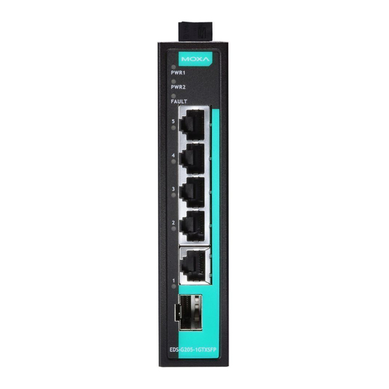
Overview The EDS-G205 series is equipped with 5 Gigabit Ethernet ports, making it an ideal and economical solution for demanding, high bandwidth Gigabit Ethernet applications. In addition, the built-in relay warning function alerts system administrators when power failures or port breaks occur. The EDS-G205 series includes 2 models: one with an operating temperature range of 0 to 60°C, and the other one with extended operating temperature range of -40 to 75°C. - Page 3 Panel Layout of EDS-G205 Front Panel View 1. Grounding screw 2. Terminal block for power input (PWR1, PWR2) and relay output 3. Power input PWR1 LED 4. Power input PWR2 LED 5. Fault LED 6. TP port’s 10/10/1000 Mbps LED 7.
-
Page 4: Mounting Dimensions (Unit = Mm)
Mounting Dimensions (unit = mm) DIN-Rail Mounting The aluminum DIN-rail attachment plate should already be fixed to the back panel of the EDS when you take it out of the box. If you need to reattach the DIN-rail attachment plate, make sure the stiff metal spring is situated towards the top, as shown in the figures below. -
Page 5: Wiring Requirements
STEP 2: 6.0 mm Mounting the EDS on the wall requires 4 screws. Use the switch, with wall mount plates attached, as a guide to mark the correct locations of the 4 screws. The heads of the screws should be less than 6.0 mm in diameter, and 3.5 mm the shafts should be less than 3.5 mm in diameter, as shown in the figure at the right. -
Page 6: Wiring The Alarm Contact
You should also pay attention to the following items: Use separate paths to route wiring for power and devices. If power wiring and device wiring paths must cross, make sure the wires are perpendicular at the intersection point. NOTE: Do not run signal or communications wiring and power wiring in the same wire conduit. -
Page 7: Wiring The Redundant Power Inputs
Wiring the Redundant Power Inputs The top two contacts and the bottom two contacts of the 6-contact terminal block connector on the EDS’s top panel are used for the EDS’s DC inputs. Top and front views of one of the terminal block connectors are shown here. STEP 1: Insert the negative/positive DC wires into the V-/V+ terminals. -
Page 8: Redundant Power Inputs
1000BaseT RJ45 Pinouts MDI-X BI_DA+ BI_DB+ BI_DA- BI_DB- BI_DB+ BI_DA+ BI_DC+ BI_DD+ BI_DC- BI_DD- BI_DB- BI_DA- BI_DD+ BI_DC+ BI_DD- BI_DC- RJ45 (8-pin) to RJ45 (8-pin) Straight-Through Cable Wiring Straight-Through Cable Switch Port NIC Port RJ45 Plug Pin 1 RJ45 RJ45 Connector Cable Wiring Connector... -
Page 9: Alarm Contact
Alarm Contact The Moxa EtherDevice Switch has one Alarm Contact located on the top panel. For detailed instructions on how to connect the Alarm Contact power wires to the two middle contacts of the 6-contact terminal block connector, see the Wiring the Alarm Contact section on page 6. -
Page 10: Led Indicators
LED Indicators The front panel of the Moxa EtherDevice Switch contains several LED indicators. The function of each LED is described in the table below. Color State Description Power is being supplied to power input PWR1 AMBER PWR1 Power is not being supplied to power input PWR1 Power is being supplied to power input PWR2... -
Page 11: Auto-Negotiation And Speed Sensing
Auto-Negotiation and Speed Sensing The EDS’s RJ45 Ethernet ports independently support auto-negotiation for transmission speeds of 10 Mbps, 100 Mbps, and 1000 Mbps, with operation according to the IEEE802.3 standard. This means that some nodes could be operating at 10 Mbps, while at the same time, other nodes are operating at 100 Mbps or 1000Mbps. - Page 12 Regulatory Approvals Safety UL508(Pending) Hazardous Location UL/cUL Class I, Division 2, Groups A, B, C, and D; ATEX Class I, Zone 2, Ex nC nL IIC T4 (Pending) FCC Part 15, CISPR (EN55022) class A EN61000-4-2 (ESD), Level 3 EN61000-4-3 (RS), Level 3 EN61000-4-4 (EFT), Level 3 EN61000-4-5 (Surge), Level 3 EN61000-4-6 (CS), Level 3...
Need help?
Do you have a question about the EtherDevice Switch EDS-G205 and is the answer not in the manual?
Questions and answers