Moxa Technologies EDS-G205A-4PoE Quick Installation Manual
Etherdevice switch
Hide thumbs
Also See for EDS-G205A-4PoE:
- Hardware installation manual (14 pages) ,
- Hardware installation manual (13 pages) ,
- Quick installation manual (14 pages)
Table of Contents
Advertisement
Quick Links
Quick Installation Guide
Moxa Americas:
Toll-free: 1-888-669-2872
Tel:
1-714-528-6777
Fax:
1-714-528-6778
Moxa Europe:
Tel:
+49-89-3 70 03 99-0
Fax:
+49-89-3 70 03 99-99
Moxa India:
Tel:
+91-80-4172-9088
Fax:
+91-80-4132-1045
EDS-G205A-4PoE
Moxa EtherDevice Switch
Edition 3.2, August 2016
Technical Support Contact Information
www.moxa.com/support
2016 Moxa Inc. All rights reserved.
Moxa China (Shanghai office):
Toll-free: 800-820-5036
Tel:
+86-21-5258-9955
Fax:
+86-21-5258-5505
Moxa Asia-Pacific:
Tel:
+886-2-8919-1230
Fax:
+886-2-8919-1231
P/N: 1802002051023
*1802002051023*
Advertisement
Table of Contents

Related Manuals for Moxa Technologies EDS-G205A-4PoE


Summary of Contents for Moxa Technologies EDS-G205A-4PoE
-
Page 1: Moxa Etherdevice Switch
EDS-G205A-4PoE Quick Installation Guide Moxa EtherDevice Switch Edition 3.2, August 2016 Technical Support Contact Information www.moxa.com/support Moxa Americas: Moxa China (Shanghai office): Toll-free: 1-888-669-2872 Toll-free: 800-820-5036 Tel: 1-714-528-6777 Tel: +86-21-5258-9955 Fax: 1-714-528-6778 Fax: +86-21-5258-5505 Moxa Europe: Moxa Asia-Pacific: Tel: +49-89-3 70 03 99-0... -
Page 2: Package Checklist
To provide greater versatility for use with applications from different industries, the EDS-G205A-4PoE switches also allow users to enable or disable broadcast storm protection, 802.3az, Jumbo frame, and PoE high power with DIP switches on the outer panel. The EDS-G205A-4PoE switches can be easily installed on a DIN-Rail or in distribution boxes. -
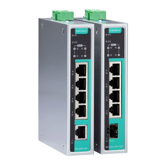
Page 3: Eds-G205A-4Poe Panel Layouts
• IP30 metal housing • DIN-rail or panel mounting ability EDS-G205A-4PoE Panel Layouts 1. Terminal blocks for P1/P2 power inputs 2. Power input P1 LED 3. Power input P2 LED 4. PoE status LED 5. 10/100/1000BaseT(X) PoE ports (ports 2, 3, 4, 5) 6. -
Page 4: Mounting Dimensions
Mounting Dimensions Unit = mm (inch) - 4 -... -
Page 5: Din-Rail Mounting
To remove the EDS from the DIN-rail, simply reverse Steps 1 and 2 above. Wall Mounting (optional) For some applications, you will find it convenient to mount the EDS-G205A-4PoE on a wall, as shown in the following figures. STEP 1: Remove the aluminum DIN-rail attachment plate from the EDS-G205A-4PoE’s... -
Page 6: Wiring Requirements
STEP 3: Once the screws are fixed on the wall, insert the four screw heads through the large parts of the keyhole-shaped apertures, and then slide the EDS downwards, as indicated. Tighten the four screws for added stability. Wiring Requirements WARNING Safety First Turn the power off before disconnecting modules or wires. -
Page 7: Grounding The Etherdevice Switch
DC power source is supplied by UL Listed Isolated Power Supply. Communication Connections The EDS-G205A-4PoE switches have 4 10/100/1000Base-T(X) PoE Ethernet ports for connecting PoE devices, and 1 10/100/1000BaseT port or 1 100/1000BaseX SFP slot for uplink connection. For fiber connections,... -
Page 8: 10/100Baset(X) Rj45 Pinouts
MDI mode and MDI-X mode. However, some PDs only support MDI mode or MDI-X mode only. The following figures show how to select the correct cable to connect between the PD and EDS-G205A-4PoE. RJ45 (8-pin) to RJ45 (8-pin) Straight-Through Cable Wiring - 8 -... -
Page 9: Redundant Power Inputs
EDS’s power needs. DIP Switch Settings The default setting for each DIP Switch is OFF. The following table explains the effect of setting the DIP Switches to the ON positions. EDS-G205A-4PoE EDS-G205A-4PoE-1GSFP (Copper Model) (SFP Model) -
Page 10: Led Indicators
ATTENTION To actively update DIP switch settings, power off and then power on the EDS. LED Indicators The front panel of the EDS switches contain several LED indicators. The function of each LED is described in the following table. Color State Description Power is being supplied to power input... -
Page 11: Triple Speed Functionality And Switching
Total Power Budget For the total power budget, the EDS-G205A-4PoE will provide 62 W at 12 to 17 VDC input, 120 W at 18 to 35 VDC input, and 144 W at 36 to 57 VDC input. -
Page 12: Poe High Power Application
PoE High Power Application PoE High Power can be enabled by DIP switch, and supply up to 36 W of PoE power when the PSE detects an 802.3af or 802.3at connection. Refer to the table below for the power budget at different input voltages, and for the number of PoE High Power Ports supported. -
Page 13: Environmental Limits
Power Input Voltage 12/24/48 VDC, redundant dual inputs Operating Voltage 12 to 57 VDC Rated Current 5.92 A @ 12 VDC 5.65 A @ 24 VDC 3.21 A @ 48 VDC Power Consumption 11.73 W without PDs’ consumption Inrush Current 17.4 A @ 24 VDC (0.1 to 1 ms) Electrical Isolation 2250 VDC to chassis for 60 s...
Need help?
Do you have a question about the EDS-G205A-4PoE and is the answer not in the manual?
Questions and answers