Table of Contents

Related Manuals for Moxa Technologies EDS-G2008-EL Series


Summary of Contents for Moxa Technologies EDS-G2008-EL Series
- Page 1 EDS-G2008-EL/ELP Series Quick Installation Guide Moxa EtherDevice Switch Version 1.0, December 2022 Technical Support Contact Information www.moxa.com/support 2022 Moxa Inc. All rights reserved. P/N: 1802020081010 *1802020081010*...
-
Page 2: Package Checklist
Overview The EDS-G2008-EL/ELP Series has an 8-port combination to simplify network expansion. There are two housing types available for the user to select depending on the requirements of their application. The ELP has a plastic housing and the EL has a metal housing. The compact switches provide a cost-effective solution for your industrial Ethernet connection requirements. - Page 3 Features High Performance Network Switching Technology • 10/100/1000BaseT(X) auto-negotiation speed, full/half duplex mode, auto MDI/MDI-X connection. • IEEE 802.3 for 10BaseT. • IEEE 802.3u for 100BaseT(X). • IEEE 802.3ab for 1000BaseT(X). • IEEE 802.3x for flow control. • IEEE 802.1p for Quality of Service (QoS) traffic prioritized function. •...
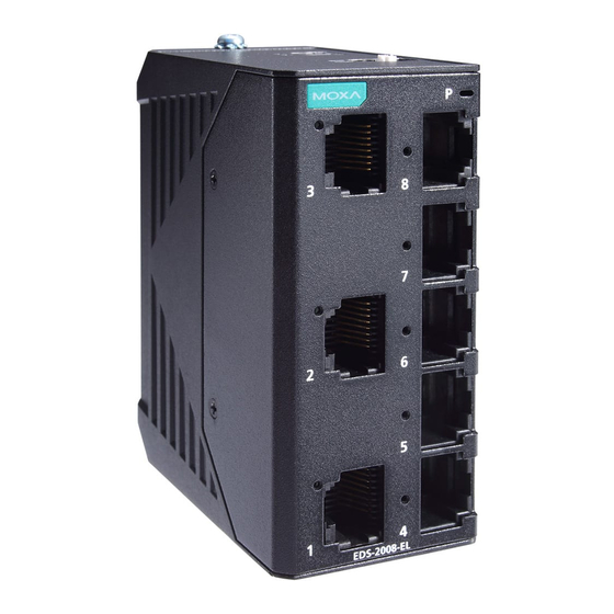
- Page 4 Panel Layout of EDS-G2008-EL/EDS-G2008-ELP 1. Chassis ground screw 2. Terminal block for power input 3. DIP switch 4. Power LED 5. 10/100/1000BaseT(X) Port 6. 10/100/1000BaseT(X) Port LED 7. Port number 8. Model name - 4 -...
-
Page 5: Mounting Dimensions
Mounting Dimensions EDS-G2008-EL Series EDS-G2008-ELP Series - 5 -... -
Page 6: Din Rail Mounting
DIN-rail Mounting When shipped, the DIN-rail mounting kit is fixed to the back panel of the EDS. Mount the EDS on the corrosion-free mounting rail that adheres to the EN 60715 standard. Suggested Installation Method STEP 1: Insert the upper lip of the DIN- rail kit into the mounting rail. - Page 7 ATTENTION When installing or removing the devices, please insert a flat- head screwdriver into the latch of the holding clamp and pull the latch downward rather than pushing it towards the DIN rail side, when removing the module from the rail. If you want to change the position of the device on the DIN rail, please follow the steps shown in the images above.
-
Page 8: Wall Mounting (Optional)
Wall Mounting (optional) For some applications, you will find it convenient to mount EDS on the wall, as illustrated below. There are two options for installation: The first option is to hook the EDS DIN-rail latch on the opening of the wall mount kit (see picture above) and then mount the wall-mount kit on the wall with screws. -
Page 9: Wiring Requirements
Wiring Requirements WARNING Do not disconnect modules or wires unless the power supply has been switched off or the area is known to be non- hazardous. The devices may only be connected to the supply voltage shown on the type plate. The devices are designed for operation with a Safety Extra-Low Voltage. -
Page 10: Wiring The Power Input
Grounding Moxa EtherDevice Switch Grounding and wire routing help limit the effects of noise due to electromagnetic interference (EMI). Run the ground connection from the ground screw to the grounding surface prior to connecting devices. A 4 mm conductor must be used when a connection to the external grounding screw is utilized. -
Page 11: Communication Connections
ATTENTION Before connecting the EDS to the DC power inputs, make sure the DC power source voltage is stable. ATTENTION Power Terminal plug wiring size 28-14 AWG, tighten to 1.7 in- lbs. Only use copper conductors. ATTENTION The cable that is connected to the field wiring terminals must be capable of withstanding at least 105°C. -
Page 12: Dip Switch Settings
RJ45 (8-pin) to RJ45 (8-pin) Straight-through Cable Wiring RJ45 (8-pin) to RJ45 (8-pin) Cross-over Cable Wiring DIP Switch Settings DIP Switch Setting Description Quality of Enable the Quality of Service to handle packet Service (QoS) priorities in four WRR queues. QoS priority mapping matrix in each queue QoS 3bit priority 7, 6... -
Page 13: Led Indicators
LED Indicators The front panel of the Moxa EtherDevice Switch contains several LED indicators. The function of each LED is described in the table below. Color State Description Power is being supplied to power input PWR. Amber Power is not being supplied to power input PWR. -
Page 14: Address Learning
Address Learning The Moxa EDS has an address table that can hold up to 4,000 node addresses, which makes it suitable for use with large networks. The address tables are self-learning, so that as nodes are added or removed, or moved from one segment to another, EDS automatically keeps up with new node locations. - Page 15 Reverse Polarity Present Protection Mechanical Casing Metal housing for EL Series; plastic housing for ELP Series Dimensions EDS-G2008-EL/ELP: (W x H x D) 36 81 65 mm (1.4 3.19 2.56 in) Weight EDS-G2008-ELP: 90 g (0.20 lb) EDS-G2008-EL: 163 g (0.36 lb) Installation DIN-rail, Wall Mounting (optional kit)