
Subscribe to Our Youtube Channel
Related Manuals for Moxa Technologies EDS-G4014 Series


Summary of Contents for Moxa Technologies EDS-G4014 Series
- Page 1 EDS-G4014 Series Quick Installation Guide Moxa EtherDevice™ Switch Version 1.0, March 2022 Technical Support Contact Information www.moxa.com/support 2022 Moxa Inc. All rights reserved. P/N: 1802040140110 *1802040140110*...
-
Page 2: Package Checklist
Package Checklist The EDS-G4014 Series industrial DIN-rail EtherDevice Switch (EDS) is shipped with the following items. If any of these items are missing or damaged, please contact your customer service representative for assistance. • 1 EDS-G4014 Ethernet switch • Quick installation guide (printed) •... -
Page 3: Mounting Dimensions
Bottom Panel View 1. microSD card slot (currently disabled) 2. Reset button 3. DIP switches for Turbo Ring, Ring Master, and Ring Coupler Mounting Dimensions DIN-rail Mounting The DIN-rail mounting kit is fixed to the back panel of the EDS device when you take it out of the box. -
Page 4: Installation
Installation STEP 1—Insert the upper lip of the DIN rail into the DIN-rail mounting kit. STEP 2—Press the EDS device towards the DIN rail until it snaps into place. Removal STEP 1—Pull down the latch on the DIN-rail mounting kit with a screwdriver. -
Page 5: Wiring Requirements
STEP 2—Mounting the EDS device on a wall requires six screws. Use the EDS device, with wall mount plates attached, as a guide to mark the correct locations of the six screws. The heads of the screws should be less than 6.0 mm in diameter, and the shafts should be less than 3.5 mm in diameter, as shown in the figure on at right. - Page 6 ATTENTION Safety First! Be sure to disconnect the power cord before installing and/or wiring your EDS device. Calculate the maximum possible current in each power wire and common wire. Observe all electrical codes dictating the maximum current allowable for each wire size. If the current goes above the maximum ratings, the wiring could overheat, causing serious damage to your equipment.
-
Page 7: Wiring The Relay Contact
In order to tighten the wire properly, ① use a small flathead NOTE We suggest the length of the pin type cable terminal is 8 mm. the terminal block connector before and during ② inserting the screwdriver to press the push-in button beside each terminal of wire. -
Page 8: Wiring The Redundant Power Inputs
Wiring the Redundant Power Inputs The EDS device includes both high-voltage and low-voltage products. For the low-voltage (LV models) products, there are two power inputs for redundancy; for the high-voltage (HV models) products, there is only one power input. Refer to the instructions and diagram below on how to connect the wires to the terminal block connector on the receptor. -
Page 9: Communication Connections
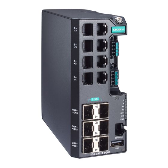
Step 3: Replace the module back on to the EDS device. Step 4: Fasten two screws on to the module. Communication Connections Each EDS-G4014 Series switch has various types of communication ports: • RJ45 console port (RS-232 interface) •... - Page 10 RJ45 Console Port Pinouts Description – USB Connection NOTE The USB function is currently reserved and may be required in the future. It should be noted that this port cannot be used for charging any devices. 1000BaseT(X) Ethernet Port Connection 1000BaseT(X) data is transmitted on differential TRD+/- signal pairs over copper wires.
-
Page 11: Reset Button
LC-Port Pinouts LC-Port to LC-Port Cable Wiring ATTENTION This is a Class 1 Laser/LED product. To avoid causing serious damage to your eyes, do not stare directly into the Laser Beam. Reset Button There are two functions available on the Reset Button. One is to reset the Ethernet switch to factory default settings by pressing and holding the Reset button for 5 seconds. -
Page 12: Device Led Indicators
Ring Master, these switches will auto-negotiate to determine which one will be the Ring Master. LED Indicators The front panel of the Moxa EDS-G4014 Series contains several LED indicators. The function of each LED is described in the following table: Device LED Indicators... - Page 13 Color State Description The system has initially failed the boot-up process • System Info. Read Fail or EEPROM information error 1. The relay contact has been triggered 2. The ingress rate limit has been exceeded and the port has entered shut down FAULT mode 3.
-
Page 14: Specifications
Color State Description 1. The switch is set as the Tail of Turbo Chain and the Chain has gone down. Blinking 2. The switch is set as the (4 times/sec) Turbo Chain’s Member/ Head and the corresponding Tail-end Chain port is down. When the switch disables the coupling or tail role of Turbo Chain. - Page 15 Pre-installed Power -LV/-LV-T models: PWR-100-LV Module -HV/-HV-T models: PWR-105-HV-I Note The EDS-G4014 Series supports modular power supplies. The model names and power parameters are determined by the installed power module. For example: EDS-G4014-T + PWR-100-LV = EDS-G4014-LV-T EDS-G4014-T + PWR-105-HV-I = EDS-G4014-HV- If you install a different power module, refer to the specifications of the corresponding model.
- Page 16 Altitude Up to 2000 m Note: Please contact Moxa if you require products guaranteed to function properly at higher altitude. Regulatory Approvals Industrial IEC 62443-4-1, IEC 62443-4-2 Cybersecurity Safety UL 61010-2-201, EN 62368-1(LVD) EN 55022/24, EN 61000-6-2/6-4 FCC Part 15 Subpart B Class A EN 61000-4-2 (ESD) Level 4 EN 61000-4-3 (RS) Level 3 EN 61000-4-4 (EFT) Level 4...
Need help?
Do you have a question about the EDS-G4014 Series and is the answer not in the manual?
Questions and answers