
Related Manuals for Moxa Technologies EDS-G205-1GTXSFP-T


Summary of Contents for Moxa Technologies EDS-G205-1GTXSFP-T
- Page 1 EDS-G205-1GTXSFP Hardware Installation Guide Moxa EtherDevice Switch First Edition, April 2015 2015 Moxa Inc. All rights reserved. P/N: 1802002051030...
-
Page 2: Package Checklist
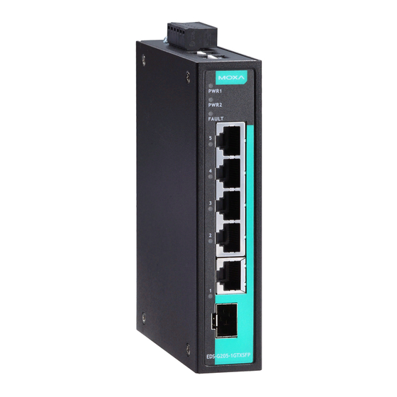
Overview The EDS-G205-1GTXSFP switches are equipped with 5 Gigabit Ethernet ports (4 10/100/1000BaseT(X) ports and 1 combo 10/100/1000BaseT(X) or 100/1000BaseSFP port), making them ideal, economical solutions for demanding, high bandwidth Gigabit Ethernet applications. In addition, the built-in relay warning function alerts system administrators when power failures or port breaks occur, and the add-on 4-pin DIP switches can be used to configure broadcast storm protection, jumbo frame rate, IEEE 802.3az energy saving, and 100/1000 SFP speed switching. -
Page 3: Panel Layout Of The Eds-G205-1Gtxsfp
Panel Layout of the EDS-G205-1GTXSFP 1. Terminal block for power input (PWR1, PWR2) and relay output 2. PWR1: LED for power input 1 3. PWR2: LED for power input 2 4. FAULT: LED indicator 5. 10/100/1000BaseT(X) LED indicator (Amber: 10/100M; Green: 1000M) 6. -
Page 4: Mounting Dimensions, Unit = Mm (Inch)
Mounting Dimensions, unit = mm (inch) - 4 -... -
Page 5: Din Rail Mounting
DIN Rail Mounting The aluminum DIN rail attachment plate should already be fixed to the back panel of the switch when you take it out of the box. If you need to reattach the DIN rail attachment plate, make sure the stiff metal spring is situated towards the top, as shown in the figures below. -
Page 6: Wiring Requirements
STEP 3: Once the screws are fixed in the wall, insert the four screw heads through the large parts of the keyhole-shaped apertures, and then slide the switch downwards, as indicated. Tighten the four screws for added stability. Wiring Requirements WARNING Safety First! Turn the power off before disconnecting modules or wires. -
Page 7: Grounding Your Moxa Switch
• We strongly advise labeling the wiring for all devices in the system. Grounding Your Moxa Switch Grounding and wire routing help limit the effects of noise due to electromagnetic interference (EMI). Run the ground connection from the ground screw to the grounding surface prior to connecting devices. ATTENTION This product is intended to be mounted to a well-grounded mounting surface, such as a metal panel. -
Page 8: Communication Connections
STEP 1: Insert the negative/positive DC wires into the V-/V+ terminals. STEP 2: To keep the DC wires from pulling loose, use a small flat-blade screwdriver to tighten the wire-clamp screws on the front of the terminal block connector. STEP 3: Insert the plastic terminal block connector prongs into the terminal block receptor, which is located on switch’s top panel. - Page 9 1000BaseT RJ45 Pinouts MDI-X BI_DA+ BI_DB+ BI_DA- BI_DB- BI_DB+ BI_DA+ BI_DC+ BI_DD+ BI_DC- BI_DD- BI_DB- BI_DA- BI_DD+ BI_DC+ BI_DD- BI_DC- RJ45 (8-pin) to RJ45 (8-pin) Straight-Through Cable Wiring RJ45 (8-pin) to RJ45 (8-pin) Cross-Over Cable Wiring 100/1000BaseSFP (mini-GBIC) Fiber Port One of the Gigabit Ethernet ports on the EDS-G205-1GTXSFP is an SFP slot, which requires 100M or 1G mini-GBIC fiber transceivers to work properly.
-
Page 10: Redundant Power Inputs
sides of the same line with the same letter (A-to-A and B-to-B, as shown below, or A1-to-A2 and B1-to-B2). LC-Port Pinouts LC-Port to LC-Port Cable Wiring ATTENTION This is a Class 1 Laser/LED product. To avoid causing serious damage to your eyes, do not stare directly into the laser beam. Redundant Power Inputs Both power inputs can be connected simultaneously to live DC power sources. -
Page 11: Led Indicators
DIP Switch Setting Description Enables broadcast storm protection Disables broadcast storm protection Enables jumbo frame function Jumbo Frame Disables jumbo frame function Enables the energy-efficient Ethernet function 802.3az Disables the energy-efficient Ethernet function Supports 100M SFP module 100/1000BaseSFP Supports 1000M SFP module Enables the corresponding PORT Alarm. -
Page 12: Auto Mdi/Mdi-X Connection
Auto MDI/MDI-X Connection The Auto MDI/MDI-X function allows users to connect the switch’s 10/100/1000BaseT(X) ports to any kind of Ethernet device, without paying attention to the type of Ethernet cable being used for the connection. This means that you can use either a straight-through cable or cross-over cable to connect the switch to Ethernet devices. - Page 13 Alarm Contact One relay output with current carrying capacity of 1A @ 24 VDC Power Requirements Input Voltage 12/24/48 VDC (9.6 to 60 VDC), redundant input Input Current @ 24VDC 0.16 A Connection One removable 6-pin terminal block Overload Current Present Protection Reverse Polarity...
Need help?
Do you have a question about the EDS-G205-1GTXSFP-T and is the answer not in the manual?
Questions and answers