
Subscribe to Our Youtube Channel
Related Manuals for Moxa Technologies EtherDevice EDS-G205A-4PoE-1GSFP


Summary of Contents for Moxa Technologies EtherDevice EDS-G205A-4PoE-1GSFP
- Page 1 EDS-G205A-4PoE Hardware Installation Guide Moxa EtherDevice Switch Second Edition, April 2014 2014 Moxa Inc. All rights reserved. P/N: 1802002051021...
-
Page 2: Package Checklist
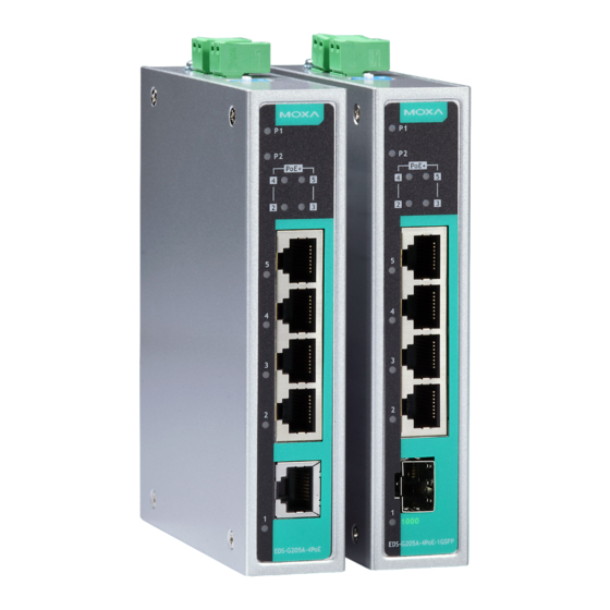
Overview The EDS-G205A-4PoE series industrial Ethernet switches are rugged entry-level industrial 5-port gigabit PoE switches that support IEEE 802.3, IEEE 802.3u, IEEE 802.3x with 10/100/1000M, full/half-duplex, MDI/MDIX auto-sensing, and IEEE 802.3af/IEEE 802.3at PoE standards. The EDS-G205A-4PoE series provides 24/48 VDC redundant power inputs that can be connected simultaneously to a live DC power source. -
Page 3: Eds-G205A-4Poe Panel Layouts
EDS-G205A-4PoE Panel Layouts 1. Terminal blocks for P1/P2 power inputs 2. Power input P1 LED 3. Power input P2 LED 4. PoE status LED 5. 10/100/1000Base-T(X) PoE ports (port 2/3/4/5) 6. TP port speed LED 7. 10/100/1000Base-T(X) port (port 1) 8. -
Page 4: Mounting Dimensions
Mounting Dimensions Unit = mm (inch) - 4 -... -
Page 5: Din-Rail Mounting
DIN-Rail Mounting The aluminum DIN-Rail attachment plate should already be fixed to the back panel of the EDS when you take it out of the box. If you need to reattach the DIN-Rail attachment plate, make sure the stiff metal spring is situated towards the top, as shown in the figures below. -
Page 6: Wiring Requirements
STEP 3: Once the screws are fixed on the wall, insert the four screw heads through the large parts of the keyhole-shaped apertures, and then slide the EDS downwards, as indicated. Tighten the four screws for added stability. Wiring Requirements WARNING Safety First Turn the power off before disconnecting modules or wires. -
Page 7: Grounding The Etherdevice Switch
Grounding the EtherDevice Switch Grounding and wire routing help limit the effects of noise due to electromagnetic interference (EMI). Run the ground connection from the ground screw to the grounding surface prior to connecting devices. ATTENTION This product is intended to be mounted to a well-grounded mounting surface such as a metal panel. -
Page 8: Communication Connections
Communication Connections The EDS-P205A-4PoE switches have 4 10/100/1000Base-T(X) PoE Ethernet ports for connecting PoE devices, and 1 10/100/1000Base-T port or 1 1000Base-X SFP slot for uplink connection. 10/100/1000Base-T(X) Ethernet Port Connection 10/100/1000Base-T(X) ports located on the EDS’s front panel are used to connect to Ethernet-enabled devices. -
Page 9: Redundant Power Inputs
RJ45 (8-pin) to RJ45 (8-pin) Straight-Through Cable Wiring RJ45 (8-pin) to RJ45 (8-pin) Cross-Over Cable Wiring NOTE If the PD only supports PoE MDI mode (V+, V+, V-, V- for pins 1, 2, 3, 6), choose a cross-over Ethernet cable to connect the PD and the EDS switch. -
Page 10: Led Indicators
ATTENTION To actively update DIP switch settings, power off and then power on the EDS. LED Indicators The front panel of the EDS switches contain several LED indicators. The function of each LED is described in the following table. Color State Description Power is being supplied to power... -
Page 11: Auto Mdi/Mdi-X Connection
Auto MDI/MDI-X Connection The Auto MDI/MDI-X function allows users to connect the EDS’s 10/100/1000Base-T(X) ports to any kind of Ethernet device, without needing to pay attention to the type of Ethernet cable being used for the connection. This means that you can use either a straight-through cable or cross-over cable to connect the EDS to Ethernet devices. - Page 12 Power Input Voltage 24/48 VDC Input Current 6.83 / 3.28 A (with full PoE+ loading) Connection Removable 4-contact terminal block Overload Current 12 A Protection Reverse Polarity Present Protection Conformance to UL Always use an “isolated power supply” to standards conform to the UL 508 standard.
Need help?
Do you have a question about the EtherDevice EDS-G205A-4PoE-1GSFP and is the answer not in the manual?
Questions and answers