Table of Contents
Advertisement
Quick Links
Quick Installation Guide
Moxa Americas:
Toll-free: 1-888-669-2872
Tel:
1-714-528-6777
Fax:
1-714-528-6778
Moxa Europe:
Tel:
+49-89-3 70 03 99-0
Fax:
+49-89-3 70 03 99-99
Moxa India:
Tel:
+91-80-4172-9088
Fax:
+91-80-4132-1045
EDS-G205A-4PoE
Moxa EtherDevice Switch
Edition 4.0, February 2017
Technical Support Contact Information
www.moxa.com/support
2017 Moxa Inc. All rights reserved.
Moxa China (Shanghai office):
Toll-free: 800-820-5036
Tel:
+86-21-5258-9955
Fax:
+86-21-5258-5505
Moxa Asia-Pacific:
Tel:
+886-2-8919-1230
Fax:
+886-2-8919-1231
P/N: 1802002051024
*1802002051024*
Advertisement
Table of Contents

Related Manuals for Moxa Technologies EtherDevice EDS-G205A-4POE-1GSFP-T


Summary of Contents for Moxa Technologies EtherDevice EDS-G205A-4POE-1GSFP-T
- Page 1 EDS-G205A-4PoE Quick Installation Guide Moxa EtherDevice Switch Edition 4.0, February 2017 Technical Support Contact Information www.moxa.com/support Moxa Americas: Moxa China (Shanghai office): Toll-free: 1-888-669-2872 Toll-free: 800-820-5036 Tel: 1-714-528-6777 Tel: +86-21-5258-9955 Fax: 1-714-528-6778 Fax: +86-21-5258-5505 Moxa Europe: Moxa Asia-Pacific: Tel: +49-89-3 70 03 99-0 Tel: +886-2-8919-1230 Fax:...
-
Page 2: Package Checklist
Overview The EDS-G205A-4PoE series industrial Ethernet switches are rugged entry-level industrial 5-port Gigabit PoE switches for environments that fall under the pollution degree 2 category. The industrial Ethernet switches support IEEE 802.3, IEEE 802.3u, and IEEE 802.3x with 10/100/1000M, full/half-duplex, MDI/MDIX auto-sensing, and IEEE 802.3af/IEEE 802.3at PoE standards. -
Page 3: Eds-G205A-4Poe Panel Layouts
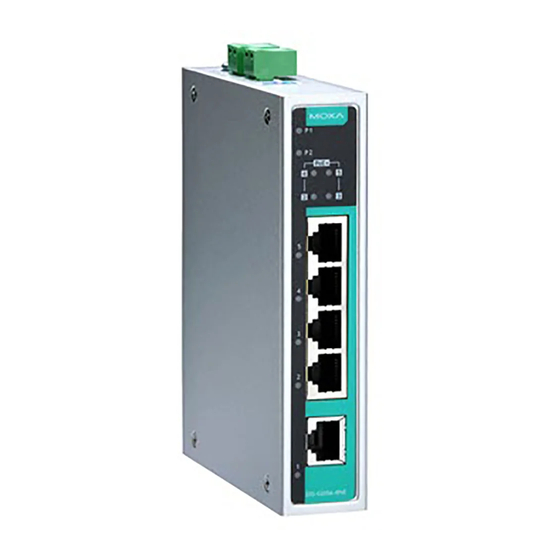
• IP30 metal housing • DIN-rail or panel mounting ability EDS-G205A-4PoE Panel Layouts 1. Terminal blocks for P1/P2 power inputs 2. Power input P1 LED 3. Power input P2 LED 4. PoE status LED 5. 10/100/1000BaseT(X) PoE ports (ports 2, 3, 4, 5) 6. -
Page 4: Mounting Dimensions
Mounting Dimensions Unit = mm (inch) - 4 -... -
Page 5: Din-Rail Mounting
DIN-Rail Mounting The aluminum DIN-rail attachment plate should already be fixed to the back panel of the EDS when you take it out of the box. If you need to reattach the DIN-rail attachment plate, make sure the stiff metal spring is situated towards the top, as shown in the figures below. -
Page 6: Wiring Requirements
STEP 3: Once the screws are fixed on the wall, insert the four screw heads through the large parts of the keyhole-shaped apertures, and then slide the EDS downwards, as indicated. Tighten the four screws for added stability. Wiring Requirements WARNING Safety First Turn the power off before disconnecting modules or wires. -
Page 7: Grounding The Etherdevice Switch
Grounding the EtherDevice Switch Grounding and wire routing help limit the effects of noise due to electromagnetic interference (EMI). Run the ground connection from the ground screw to the grounding surface prior to connecting devices. ATTENTION This product is intended to be mounted to a well-grounded mounting surface such as a metal panel. -
Page 8: 10/100Baset(X) Rj45 Pinouts
10/100BaseT(x) RJ45 Pinouts MDI Port Pinouts MDI-X Port Pinouts 8-pin RJ45 Signal Signal 1000BaseT RJ45 Pinouts MDI-X BI_DA+ BI_DB+ BI_DA- BI_DB- BI_DB+ BI_DA+ BI_DC+ BI_DD+ BI_DC- BI_DD- BI_DB- BI_DA- BI_DD+ BI_DC+ BI_DD- BI_DC- PoE Ethernet Port Connection PoE ports located on the EDS switch’s front panel are used to connect to PoE-enabled devices. -
Page 9: Redundant Power Inputs
RJ45 (8-pin) to RJ45 (8-pin) Cross-Over Cable Wiring NOTE If the PD only supports PoE MDI mode (V+, V+, V-, V- for pins 1, 2, 3, 6), choose a cross-over Ethernet cable to connect the PD and the EDS switch. If the PD only supports PoE MDI-X mode (V-, V-, V+, V+ for pins 1, 2, 3, 6), choose a straight-through Ethernet cable between the PD and the EDS switch. -
Page 10: Led Indicators
ATTENTION To actively update DIP switch settings, power off and then power on the EDS. LED Indicators The front panel of the EDS switches contain several LED indicators. The function of each LED is described in the following table. Color State Description Power is being supplied to power input... -
Page 11: Triple Speed Functionality And Switching
Triple Speed Functionality and Switching The Moxa EtherDevice Switch’s 10/100/1000 Mbps switched RJ45 port auto negotiates with the connected device for the fastest data transmission rate supported by both devices. All models of Moxa EtherDevice Switch are plug-and-play devices, so that software configuration is not required at installation, or during maintenance. -
Page 12: Poe High Power Application
PoE High Power Application PoE High Power can be enabled by DIP switch, and supply up to 36 W of PoE power when the PSE detects an 802.3af or 802.3at connection. Refer to the table below for the power budget at different input voltages, and for the number of PoE High Power Ports supported. - Page 13 Power Input Voltage 12/24/48 VDC, redundant dual inputs Operating Voltage 12 to 57 VDC Rated Current 5.92 A @ 12 VDC 5.65 A @ 24 VDC 3.21 A @ 48 VDC Power Consumption 11.73 W without PDs’ consumption Inrush Current 17.4 A @ 24 VDC (0.1 to 1 ms) Electrical Isolation 2250 VDC to chassis for 60 s...
Need help?
Do you have a question about the EtherDevice EDS-G205A-4POE-1GSFP-T and is the answer not in the manual?
Questions and answers