
Subscribe to Our Youtube Channel
Related Manuals for Planet IPOE-E174


Summary of Contents for Planet IPOE-E174
- Page 1 1-Port Ultra PoE to 4-Port 802.3af/at Gigabit PoE Extender IPOE-E174 User’s Manual...
-
Page 2: Table Of Contents
2.1 Physical Dimensions ............11 2.2 Front Panel ...............12 2.3 Mounting Installation ............14 2.3.1 DIN-rail Mounting ............14 2.3.2 Wall-mount Plate Mounting .........15 2.4 Connecting IPOE-E174 to Power Source Equipment (PSE) ..16 2.5 Connecting IPOE-E174 to Powered Device (PD) ....17 3. Customer Support ..............19... -
Page 3: Introduction
Thank you for purchasing PLANET IPOE-E174- 1-Port Ultra PoE to 4-Port 802.3af/at Gigabit PoE Extender. Open the box of the IPOE-E174 and carefully unpack it. The box should contain the following items: „ Industrial Power over Ethernet Extender x 1 „... -
Page 4: Application Diagram
1.2 Application Diagram The IPOE-E174 is designed as the repeater to forward both Gigabit Ethernet data and IEEE 802.3at PoE power, thus extending the range of PoE installation. With just plug and play and without additional power supply and setup, one single IPOE-E174 can increase the PoE range to 200m and drive up four remote PoE IP cameras or wireless access point. -
Page 5: Key Features
1.3 Key Features Physical Port „ 5-port 10/100/1000BASE-T Gigabit RJ45 interface 1-port data + power input 4-port data + power output Power over Ethernet „ 1-port data + power input Complies with ultra Power over Ethernet end-span and mid- span PD ... - Page 6 „ Automatic address learning and address aging „ Supports CSMA/CD protocol Industrial Case / Installation „ IP30 aluminum case protection „ DIN rail and wall-mount design „ Supports EFT protection for 6000V DC power, and 6000V DC Ethernet ESD protection „...
-
Page 7: Technical Specifications
1.4 Technical Specifications Model IPOE-E174 Hardware Specifications PoE In Port 1 x 10/100/1000BASE-T Ethernet with ultra PoE “Data + DC” in, auto MDI/MDI-X, auto-negotiation RJ45 connector Network Connector PoE Out Port 4 x 10/100/1000BASE-T Ethernet with IEEE 802.3af/at PoE “Data + DC” out, auto MDI/MDI-X, auto-negotiation RJ45 connector... - Page 8 System: PWR (Green) Power Input: Midspan in (Green) Power Input: Endspan in (Green) PoE Power Usage (%): 25 (Green) PoE Power Usage (%): 50 (Green) LED Display PoE Power Usage (%): 75 (Green) PoE Input Port: LNK/ACT (Green) PoE Input Port: PoE in (Orange) Per PoE Output Port: LNK/ACT (Green) Per PoE Output Port: PoE-in-Use (Orange) Twisted-pair cable:...
- Page 9 PoE in Port 50~57V DC, max. 60 watts PoE Power Per PoE out Port 44~55V DC, max. 30.8 watts PoE in Port 1/2(+), 3/6(-); 4/5(+), 7/8(-) Power Pin Assignment Per PoE out Port 1/2(+), 3/6(-) 50 watts (max.) @ Ultra PoE input PoE Power Budget 20 watts (max.) @ IEEE 802.3at PoE+ input No support @ IEEE 802.3af PoE input...
-
Page 10: Power Over Ethernet Budget
IPOE-E174: PoE Output Max. Number of PDs Power Source Budget* supported Class 4 PD@25-watt 2 units PLANET Ultra PoE PSE 50 watts max. Class 3 PD@15-watt 3 units Class 2 PD@7-watt 4 units Class 4 PD@25-watt 0 IEEE 802.3at PoE+ 20 watts max. -
Page 11: Installation
2. InSTALLATION 2.1 Physical Dimensions IPOE-E174 1-port Ultra PoE to 4-port 802.3af/at Gigabit PoE Extender dimensions (W x D x H): 135 x 87.8 x 56 mm DIN-Rail Kit 4-Port PoE Extender... -
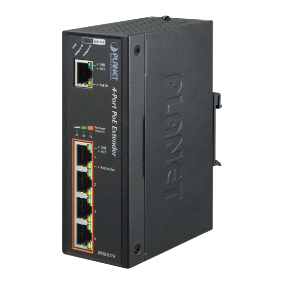
Page 12: Front Panel
Figure 2-1: IPOE-E174 Front Panel System Color Function Light to indicate IPOE-E174 has power. Green Light to indicate IPOE-E174 is working in Midspan IN Green midspan mode and offers up to 30-watt power. Light to indicate IPOE-E174 is working in... - Page 13 Function Light to indicate the port is linked up. LNK/ACT Green Blink to indicate that the IPOE-E174 is actively sending or receiving data over that port. PoE In Orange Light to indicate IPOE-E174 has power. Per PoE Output Port (Port 1 ~ 4)
-
Page 14: Mounting Installation
Extender and make connections to it. Please read the following topics and perform the procedures in the order being presented. In the installation steps below, this Manual uses IGS-801 (PLANET 8 Port Industrial Gigabit Switch) as an example. However, the steps for PLANET Industrial Power over Note Ethernet Extender are similar. -
Page 15: Wall-Mount Plate Mounting
Please refer to the following procedures to remove the Industrial Power over Ethernet Extender from the track. Step 3: Lightly remove the DIN rail from the track. 2.3.2 Wall-mount Plate Mounting To mount the Industrial Power over Ethernet Extender on the wall, please follow the instructions described below. -
Page 16: Connecting Ipoe-E174 To Power Source Equipment (Pse)
Step 4: Use the hook holes in the corners of the wall-mount plate to hang the Industrial Gigabit Ethernet Switch on the wall. Step 5: To remove the wall-mount plate, reverse the steps above. 2.4 Connecting IPOE-E174 to Power Source Equipment (PSE) This section describes how to install the Industrial Power over Ethernet Extender and make connections to it. -
Page 17: Connecting Ipoe-E174 To Powered Device (Pd)
Step 2: The PSE delivers both Ethernet Data and PoE power over UTP cable to the IPOE-E174 and the “PoE IN” LED will be lit steadily. 1. When the LED turns steady green, it means the IPOE-E174 is being powered successfully with PoE. - Page 18 Step 3: Once the IPOE-E174 detects the existence of an IEEE 802.3at/af device, the “PoE In-Use” LED indicator will be lit steadily, showing it is providing power. Power Ultra PoE/60W Data IEEE 802.3at/25W IEEE 802.3at/25W PoE PTZ IP Cemera Power...
-
Page 19: Customer Support
3. Customer Support Thank you for purchasing PLANET products. You can browse our online FAQ resource and User’s Manual on PLANET Web site first to check if it could solve your issue. If you need more support information, please contact PLANET switch support team.
Need help?
Do you have a question about the IPOE-E174 and is the answer not in the manual?
Questions and answers