
Related Manuals for Planet IVC-234GT


Summary of Contents for Planet IVC-234GT
- Page 1 Industrial 1-Port BNC/RJ11 to 4-Port Gigabit Ethernet Extender IVC-234GT User’s Manual...
- Page 2 PLANET has made every effort to ensure that this User’s Manual is accurate; PLANET disclaims liability for any inaccuracies or omissions that may have occurred.
- Page 3 Do not dispose of WEEE as unsorted municipal waste and have to collect such WEEE separately. Revision PLANET Industrial 1-Port BNC/RJ11 to 4-Port Gigabit Ethernet Extender User’s Manual For Models: IVC-234GT Revision: 1.0 (May 2018)
-
Page 4: Table Of Contents
2. Hardware Introduction ..............6 2.1 Physical Dimensions.............. 6 2.2 Front View ................7 2.3 Top View ................8 2.4 IVC-234GT LED Indicators ............. 8 2.5 DIP Switch and Link Type............9 3. Product Specifications ..............12 4. Applications ................14 4.1 Point-to-Point Application -- LAN to LAN Connection ....14 4.2 Point to Multi-point Application (IP surveillance) .....16... -
Page 5: Package Contents
1. Package Contents Thank you for purchasing PLANET Industrial 1-Port BNC/RJ11 to 4-Port Gigabit Ethernet Extender, IVC-234GT. In the following sections, the term “Industrial Ethernet Extender” means the IVC-234GT. Open the box of the Industrial Ethernet Extender and carefully unpack it. -
Page 6: Hardware Introduction
Dimensions (W x D x H): 32 x 135 x 87.8mm Top View Mounting Kit Side View Front View Side View Rear View FAULT VDSL Inter G.INP Symm Asymm 12dB DIN-Rail Kit 1000 RJ11 RJ11 Bottom View Mounting Kit Dimensions ( unit = mm ) Figure 2-1: IVC-234GT Three-View Diagram... -
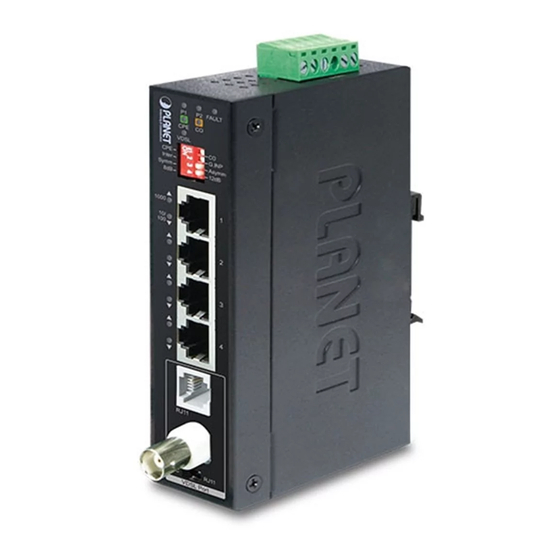
Page 7: Front View
1000 RJ11 RJ11 VDSL Port Figure 2-2: IVC-234GT Front Panel The unit’s front panel provides the following simple interfaces: LEDs for Power 1, Power 2 and VDSL2 4 10/100/1000BASE-T RJ45 ports BNC female/ RJ11 connector via DIP switch ... -
Page 8: Top View
V2+ V2- Input PWR1 Fault PWR2 DC12~48V, AC 24V Figure 2-3: IVC-234GT Top View 2.4 IVC-234GT LED Indicators The rich diagnostic LEDs on the front panel can provide the operating status of individual port and whole system. System Color... -
Page 9: Dip Switch And Link Type
100/1000BASE-T Port Color Function Indicates that the port is operating at 1000Mbps. Indicates that the Industrial Ethernet 1000 Green Blink Extender is actively sending or receiving data over that port at 1000Mbps. Indicates that the port is link down or 10/100Mbps. - Page 10 By default, the 4-position switches of the DIP switch, set at the “ON” position, are operated as “CPE”. For oper- ating as “CO”, please turn DIP 1 switch to the “OFF” position. Then adjust other DIP switches accordingly to Note fulfill different network application demands.
- Page 11 DIP-3: Band Profile (Asymmetric/Symmetric) The asymmetric mode provides more bandwidth Asymmetric than the other side. This mode provides the highest bandwidth in short range. With the G.997 band plan supported, the symmetric Symmetric mode can provide almost the same rate of downstream and upstream.
-
Page 12: Product Specifications
3. Product Specifications Product IVC-234GT Hardware Specifications TP interface 4 10/100/1000BASE-T RJ45 auto-MDI/MDI-X ports 1 BNC female Ethernet over Coaxial Coaxial cable: 75 ohm Cabling RG-6/U cable, less than12Ω/1000 ft RG-59/U cable, less than 30Ω/1000 ft. VDSL Maximum Max. 1200m with data transmission Distance (3,937ft.) - Page 13 System Specifications VDSL-DMT ITU-T G.993.1 VDSL ITU-T G.997.1 VDSL ITU-T G.993.2 VDSL2 (Profile 17a/30a Support) Compliance ITU-T G.993.5 G. Vectoring ITU-T G.998 G.INP Standards Conformance IEEE 802.3 Ethernet IEEE 802.3u Fast Ethernet IEEE 802.3ab Gigabit Ethernet Standards ITU-T G.993.1 VDSL Compliance...
-
Page 14: Applications
4. Applications The Industrial Ethernet Extender does not require any software configuration. Users can immediately use any feature of this product simply by attaching the cables and turning the power on. There are some key limitations on the Industrial Ethernet Extender. Please check the following items. - Page 15 4. Power, CO and CPE LEDs will illuminate correspondingly. 5. Connect coaxial cable from LAN1 IVC-234GT to VDSL BNC port of the LAN2 IVC-234GT. 6. VDSL LNK LED will blink to illuminate at both Industrial Ethernet Extenders.
-
Page 16: Point To Multi-Point Application (Ip Surveillance)
Refer to the following procedure to set up many pairs of IVC-234GT to IP surveillance system. 1. Set the IVC-234GT to be the CO and CPE mode from the DIP switch on the front panel. 2. Power on the IVC-234GT by connecting its power source. -
Page 17: Installations
5. Installations 5.1 Wiring the Power Inputs The 6-contact terminal block connector on the top panel of Industrial Ethernet Extender is used for two DC redundant power inputs. Please follow the steps below to insert the power wire. When performing any of the procedures like inserting the wires or tightening the wire-clamp screws, make sure the power is OFF to prevent from getting an electric Caution... -
Page 18: Wiring The Fault Alarm Contact
5.2 Wiring the Fault Alarm Contact The fault alarm contacts are in the middle of the terminal block connector as the picture shows below. Inserting the wires, the Industrial Ethernet Extender will detect the fault status of the power failure and then forms an open circuit. The following illustration shows an application example for wiring the fault alarm contacts. -
Page 19: Din-Rail Mounting Installation
5.3 DIN-rail Mounting Installation The DIN-rail bracket is screwed on the Industrial Ethernet Extender when out of factory. Please refer to the following steps for DIN-rail mounting: Step 1: Screw the DIN-rail bracket on the Industrial Ethernet Extender. Step 2: Lightly insert the bottom of the switch into the track. - Page 20 Step 3: Make sure the DIN rail is tightly secured on the track. Step 4: Please refer to the following procedure to remove the Industrial Ethernet Extender from the track. Step 5: Lightly pull out the bottom of DIN rail for removing it from the track.
-
Page 21: Wall-Mount Plate Mounting
5.4 Wall-mount Plate Mounting To install the Industrial Ethernet Extender on the wall, please follow the instructions described below. Step 1: Remove the DIN-rail bracket from the Industrial Ethernet Extender with a screwdriver. Step 2: Place the wall-mount plate on the rear panel of the Industrial Ethernet Extender. -
Page 22: Performance Table
6. Performance Table Industrial Ethernet Extender Upstream/Downstream Performance with RJ11 connection Interleave CO DIP Switch (Upstream/Downstream) Asymmetric Symmetric Distance (meter) 12dB 12dB 93/190 85/174 143/148 132/136 67/164 59/146 118/119 103/104 38/116 28/94 71/75 59/60 24/59 22/49 49/36 38/27 1000 9/45 7/40 21/25... - Page 23 Industrial Ethernet Extender Upstream /Downstream Performance with BNC connection Interleave CO DIP Switch (Upstream/Downstream) Asymmetric Symmetric Distance (meter) 12dB 12dB 84/184 75/169 131/144 125/128 49/148 54/128 93/118 89/99 36/100 26/80 77/66 64/53 21/50 17/39 44/30 37/26 1000 7/42 5/29 20/25 19/28 1200...
-
Page 24: Troubleshooting
IVC-234GT units. Please also try to adjust the DIP switch of the IVC-234GT to the other SNR mode. 2. Please note you must use one IVC-234GT in CO mode and the other IVC-234GT in CPE mode to make connection to each other work. -
Page 25: Faqs
Generally speaking, the higher SNR value gets, the better the line quality gets, but performance is lower. Q3: What is the best distance for IVC-234GT? A3: In order to guarantee the stability and better quality of network, we suggest the distance should not exceed 1.2 kilometers. -
Page 26: Customer Support
9. Customer Support Thank you for purchasing PLANET products. You can browse our online FAQ resource and User’s Manual on PLANET Web site first to check if it could solve your issue. If you need more support information, please contact PLANET switch support team. - Page 27 *Model Number : IVC-234GT * Produced by: Manufacturer‘s Name : Planet Technology Corp. Manufacturer‘s Address : 10F., No.96, Minquan Rd., Xindian Dist., New Taipei City 231, Taiwan, R.O.C. is herewith confirmed to comply with the requirements set out in the Council Directive on the Approximation of the Laws of the Member States relating to Electromagnetic Compatibility Directive on (2014/30/EU).
Need help?
Do you have a question about the IVC-234GT and is the answer not in the manual?
Questions and answers