Table of Contents
Advertisement
Quick Links
Advertisement
Table of Contents

Summary of Contents for Planet POE-E301
- Page 1 1-Port 802.3bt to 1-Port 802.3bt Gigabit PoE++ Extender POE-E301 User's Manual...
-
Page 2: Table Of Contents
3.4 DIP Switch ..................7 4. Hardware Installation ................8 4.1 Before Installation ................8 4.2 Connecting POE-E301 to the PSE ............ 8 4.3 Connecting POE-E301 to the PD ............9 4.4 Multiple PoE Extender Installation ..........10 4.5 Grounding the Device ..............11 4.6 Wall-mount Installation .............. -
Page 3: Package Contents
1. Package Contents Thank you for purchasing PLANET IEEE 802.3bt PoE++ Extender, POE-E301. Open the box of the PoE++ Extender and carefully unpack it. The box should contain the following items: IEEE 802.3bt PoE++ Extender x 1 QR Code Sheet x 1 Let’s get started with your PLANET product POE-E301 Please scan the QR code to browse our online User’s Manual or Quick... -
Page 4: Product Features
2. Product Features z Compliant with IEEE 802.3bt PoE++ PSE and PD standard z Backward compatible with IEEE 802.3at/af PoE z Complies with IEEE 802.3/802.3u/802.3ab 10/100/1000BASE-T z Extends the range of PoE by an additional 100 meters (328ft.) z Automatically detects and protects PoE equipment from being damaged by incorrect installation z Multiple units allowed with daisy-chain installation support z Forwards both Ethernet data and PoE power to remote device... -
Page 5: Hardware Introduction
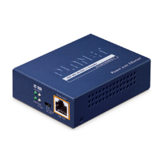
3.1 Product Outlook IEEE 802.3bt PoE ++ Extender 10/100/1000BASE-T Power over Ethernet 3.2 Ports Connection Connect the PoE IN port of the POE-E301 to any of the following 802.3af/802.3at/802.3bt PSE devices like in this case a PoE injector through a CAT-5/5e/6 UTP cable: PoE IN Port z PoE injector... -
Page 6: Led Definition
3.3 LED Definition: 10/100/1000T LNK/ACT PWR PoE- UPoE PoE OUT in-Use Color Function To indicate the port is receiving 802.3af/ Lit: at/bt PoE PSE Green To indicate that the PoE power is not Off: detected. To indicate the link through port is Lit: successfully established. -
Page 7: Dip Switch
3.4 DIP Switch PoE Mode Function This mode makes the POE-E301 series fully support IEEE (Default) 802.3af/at/bt standards. This mode makes the POE-E301 series fully support Cisco UPoE UPOE or PoH standards... -
Page 8: Hardware Installation
If there are any far-away IEEE 802.3bt/802.3at/802.3af devices that need to be powered on, the POE-E301 can provide you with a way to supply power to this Ethernet device conveniently. z The POE-E301 is installed between the PSE and the PD; it is powered by PSE and forwards the Ethernet data and remaining PoE power to the PD. -
Page 9: Connecting Poe-E301 To The Pd
Step 4: The “PoE OUT” port is a power injector that transmits data and power simultaneously between the PSE and PD. Step 5: Once the POE-E301 detects a UPOE PD device, the “PoE-in-Use” LED indicator will light up in amber to show it is providing power. -
Page 10: Multiple Poe Extender Installation
802.3bt/802.3at/802.3af standard or in-line power device, the PoE OUT LED indicator of the POE-E301 will not be turned on. 2. When the DIP switch of the POE-E301 is set to “BT” mode, according to the IEEE 802.3bt/at/af standard, the POE-E301 will not inject power if the PD is not the said standard. -
Page 11: Grounding The Device
1. Each POE-E301 can withstand a maximum of 2.4 watts. Check the total power consumption of your IEEE 802.3bt/at/ af PD and the POE-E301 before you make the daisy-chain connection. If the overall power consumption is overloaded, the local PSE could shut down the whole power system. -
Page 12: Wall-Mount Installation
Step 3: Hang the POE-E301 on the screws from the wall. 4.7 DIN-rail Mounting (Optional) There are two DIN-rail holes on the left side of the POE-E301 that allows it to be easily mounted on the DIN rail. If the DIN-rail mounting is opted, the DIN-rail mounting kit (RKE-DIN) has to be ordered as it is not included in the package. The following steps for DIN-rail mounting are shown below:... - Page 13 Step 2: First put the upper DIN-rail bracket on to the rail shown below and then the lower bracket on to the rail to finish the mounting. Step 3: Make sure the POE-E301 unit is tightly fixed on the track. You must use the screws supplied with the mounting brackets. Damage caused to the parts by using incorrect screws would invalidate your warranty.
-
Page 14: Product Specifications
5. Product Specifications Model POE-E301 Interfaces 1 x 10/100/1000BASE-T Ethernet with IEEE 802.3bt/at/af PoE “Data + DC” in Auto MDI/ PoE IN MDI-X, auto-negotiation RJ45 connector 1 x 10/100/1000BASE-T Ethernet with IEEE 802.3bt/at/af PoE “Data + DC” out Auto MDI/ PoE OUT... - Page 15 ESD (Ethernet): 2KV Protection Surge (EFT for power): 2KV PWR (Green) PoE IN: TP 10/100/1000BASE-T (Green) LED Indicators PoE OUT: TP 10/100/1000BASE-T (Green) PoE-in-Use (Green: BT PD; Amber UPOE PD) 10BASE-T: 4-pair UTP Cat. 5 up to 100m (328ft) 100BASE-TX: 4-pair UTP Cat. 5 up to 100m (328ft) Network Cable 1000BASE-T: 4-pair UTP Cat. 5e, 6, 7 up to 100m (328ft) EIA/TIA-568 100-ohm STP (100m or 328ft) Switching Specifications Switch Architecture Store-and-Forward 10Mbps: 14880pps@64Bytes Switch Throughput 100Mbps: 148810pps@64Bytes 1000Mbps: 1488000pps@64Bytes Maximum Frame Size 9K bytes Back pressure for half duplex Flow Control IEEE 802.3x pause frame for full duplex Standards Conformance...


Need help?
Do you have a question about the POE-E301 and is the answer not in the manual?
Questions and answers