
Subscribe to Our Youtube Channel
Related Manuals for Planet IPOE-E202


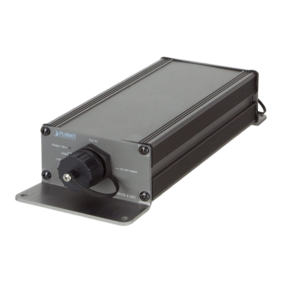
Summary of Contents for Planet IPOE-E202
- Page 1 Industrial 1-port 802.3at PoE+ to 2-port 802.3af PoE Extender IPOE-E202 User’s Manual...
- Page 2 PLANET has made every effort to ensure that this User’s Manual is accurate; PLANET disclaims liability for any inaccuracies or omissions that may have occurred.
- Page 3 Do not dispose of WEEE as unsorted municipal waste and have to collect such WEEE separately. Revision PLANET Industrial 1-Port 802.3at PoE+ to 2-Port 802.3af PoE Extender User’s Manual FOR MODEL: IPOE-E202 REVISION: 2.0 (JULY, 2017)
-
Page 4: Table Of Contents
2.4.1 Making Waterproof RJ45 Cable ........15 2.4.2 Wall Mounting ............16 2.4.3 Connecting waterproof RJ45 connector to the IPOE-E202 .............17 2.5 Connecting IPOE-E202 to Power Source Equipment (PSE) ..19 2.6 Connecting IPOE-E202 to Powered Device (PD) ....20 3. Customer Support ..............22 APPENDIX A: Networking Connection ..........23 A.1 Switch’s RJ45 Pin Assignments ..........23... -
Page 5: Introduction
The chapter explains the feature, functionality and the physical installation of the Industrial PoE Extender. Chapter 3 Customer Support The chapter explains how to get support from PLANET. Appendix A This chapter contains cable information of the Industrial PoE Extender. - Page 6 Power over Ethernet „ 1-port data + power input Complies with IEEE 802.3at Power over Ethernet Plus end- span/mid-span PD Supports PoE input power up to 30.8 watts „ 2-port data + power output Complies with IEEE 802.3af/IEEE 802.3at Power over Ethernet/ end-span PSE ...
- Page 7 Industrial Case and Installation „ IP63 aluminum case „ Wall-mount design „ Waterproof and dustproof „ Supports EFT protection of 2000 VDC for power line „ Supports 2000 VDC Ethernet ESD protection „ -40 to 75 degrees C operating temperature „...
-
Page 8: Product Specifications
1.4 Product Specifications Model IPOE-E202 Hardware Specifications Hardware Version PoE In Port 1 x 10/100/1000BASE-T Ethernet with High PoE “Data + Power” in, auto MDI/MDI-X, auto-negotiation RJ45 connector Network Connector PoE Out Port 2 x 10/100/1000BASE-T Ethernet with IEEE 802.3af/at PoE “Data + Power” out, auto... - Page 9 Dimensions (W x D x H) 199.6 x 81 x 40 mm Weight 373g 30 watts/102.3BTU (Full loading with PoE Power Consumption function) Power over Ethernet PoE In Port IEEE 802.3at Power over Ethernet Plus end-span/mid-span PD class 4 PD Per PoE Out Port PoE Standard IEEE 802.3at Power over Ethernet Plus...
-
Page 10: Power Over Ethernet Budget
1.5 Power over Ethernet Budget The following table lists how many PoE devices can be powered by IPOE-E202: PoE Output Max. Number of PDs Power Source Budget* supported Class 4 PD@25 1 unit watts IEEE 802.3at PoE+ Class 3 PD@15 25 watts max. -
Page 11: When Pse/Poe Switch Output Is Dc 56V
25.8 24.8 100M 13.2 16.7 100M 10.3 100M 13.2 100M 12.4 100M 100M 100M 1.6.2 When PSE/PoE Switch Output is DC 56V A (Distance) B (Distance) C (Watts) 25.8 24.7 100M 23.5 25.7 25.4 24.4 100M 22.2 24.5 24.2 21.7 100M 17.5 100M... -
Page 12: Installation
Basic knowledge of networking is assumed. Please read this chapter completely before continuing. 2.1 Physical Dimensions IPOE-E202 industrial 1-port 802.3at PoE+ to 2-port 802.3af PoE extender dimensions: (W x D x H): 199.6 x 80 x 40 mm PoE 1 Out... -
Page 13: Front Panel
Green Lights to indicate the IPOE-E202 has power. PoE Input Port Color Function Blinks to indicate that the IPOE-E202 is actively LNK/ACT Orange sending or receiving data over that port. Lights to indicate the IPOE-E202 is successfully connecting to the network at 1000Mbps. -
Page 14: Rear Panel
Color Function Lights to indicate the port is linked up at 10/100/1000Mbps. LNK/ACT Green Blinks to indicate that the IPOE-E202 is actively sending or receiving data over that port. Lights to indicate the port is providing PoE power. PoE-in-Use Orange Off to indicate the connected device is not a PoE Powered Device (PD). -
Page 15: Making Waterproof Rj45 Cable
2.4.1 Making Waterproof RJ45 Cable Step 1: Take a waterproof RJ45 jack out from the IPOE-E202 box and prepare one RJ45 cable. Step 2: Insert the RJ45 cable through the waterproof RJ45 jack. Step 3: Prepare an RJ45 connector. Step 4: Put the RJ45 connector in place with cable crimper. -
Page 16: Wall Mounting
Note 3. Never use any waterproof RJ45 connector that is not purchased from PLANET or doesn’t have the same dimensions of the IPOE-E202; it will damage the device permanently. 2.4.2 Wall Mounting To install the industrial PoE extender on the wall, please follow the... -
Page 17: Connecting Waterproof Rj45 Connector To The Ipoe-E202
Step 1: Take the four screws from the box. Step 2: Place the IPOE-E202 on the wall. Step 3: Use a screwdriver to screw it into the wall. 2.4.3 Connecting waterproof RJ45 connector to the IPOE-E202 Step 1: Insert the waterproof RJ45 connector into the port of the... - Page 18 Step 2: Turn clockwise to tighten the screw nut.
-
Page 19: Connecting Ipoe-E202 To Power Source Equipment (Pse)
PSE/PoE Switch IPOE-E202 Step 2: The PSE delivers both Ethernet Data and PoE power over UTP cable to the IPOE-E202 and the “PoE IN” LED will be lit steadily. 1. When the LED turns steady green, it means the IPOE- E202 is being powered successfully with PoE. -
Page 20: Connecting Ipoe-E202 To Powered Device (Pd)
2.6 Connecting IPOE-E202 to Powered Device (PD) Step 1: Connect the additional Cat5e/6 cable that will be used to connect to the remote Powered Device (PD) to the “PoE-in-Use” port of the IPOE-E202. PoE Wireless AP IPOE-E202 PoE Camera Step 2: The “PoE-in-Use” port is also the power injector which transmits DC voltage to the Cat5e/6 cable and transfer data and power simultaneously between the PSE and PD. - Page 21 Step 3: Once the IPOE-E202 detects the existence of an IEEE 802.3at/af device, the “PoE-in-Use” LED indicator will be lit steadily, showing it is providing power. 1 In 1 Out Power PoE+/30W 100m Data IEEE 802.3at/25W 100m PoE Injector/Switch PoE PTZ IP Camera...
-
Page 22: Customer Support
3. Customer Support Thank you for purchasing PLANET products. You can browse our online FAQ resource and user’s manual on PLANET web site first to check if it could solve your issue. If you need more support information, please contact PLANET switch support team. -
Page 23: Appendix A: Networking Connection
APPENDIX A: Networking Connection A.1 Switch’s RJ45 Pin Assignments 1000Mbps, 1000BASE-T Contact MDI-X BI_DA+ BI_DB+ BI_DA- BI_DB- BI_DB+ BI_DA+ BI_DC+ BI_DD+ BI_DC- BI_DD- BI_DB- BI_DA- BI_DD+ BI_DC+ BI_DD- BI_DC- 10/100Mbps, 10/100BASE-TX RJ45 Connector pin assignment MDI-X Contact Media Dependent Media Dependent Interface Interface-Cross Tx + (transmit) -
Page 24: Rj45 Cable Pin Assignments
A.2 RJ45 Cable Pin Assignments The standard RJ45 receptacle/connector There are 8 wires on a standard UTP/STP cable and each wire is color- coded. The following shows the pin allocation and color of straight- through cable and crossover cable connection: Straight Cable SIDE 1 SIDE 2...
Need help?
Do you have a question about the IPOE-E202 and is the answer not in the manual?
Questions and answers