
Subscribe to Our Youtube Channel
Related Manuals for Planet IPOE-E172


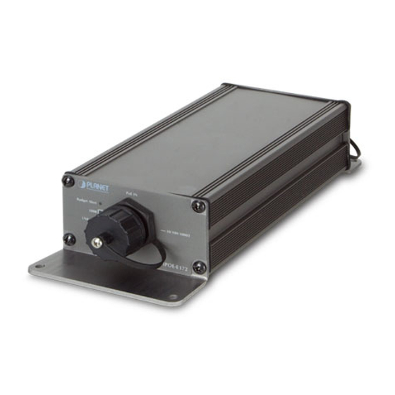
Summary of Contents for Planet IPOE-E172
- Page 1 Industrial 1-port Ultra PoE to 2-port 802.3bt/at Gigabit PoE Extender IPOE-E172 User’s Manual...
- Page 2 PLANET has made every effort to ensure that this User’s Manual is accurate; PLANET disclaims liability for any inaccuracies or omissions that may have occurred.
- Page 3 Do not dispose of WEEE as unsorted municipal waste and have to collect such WEEE separately. Revision PLANET Industrial 1-Port Ultra PoE to 2-Port 802.3bt/at Gigabit PoE Extender User's Manual FOR MODEL: IPOE-E172 REVISION: 1.0 (SEPTEMBER, 2017)
-
Page 4: Table Of Contents
2.4.1 Making Waterproof RJ45 Cable ........15 2.4.2 Wall Mounting ............16 2.4.3 Connecting Waterproof RJ45 Connector to the IPOE-E172 .............17 2.5 Connecting IPOE-E172 to Power Source Equipment (PSE) ..19 2.6 Connecting IPOE-E172 to Powered Device (PD) .....20 3. Customer Support ..............22 APPENDIX A: Networking Connection ..........23 A.1 Switch’s RJ45 Pin Assignments..........23... -
Page 5: Introduction
1. Introduction 1.1 Package Contents Check your package for the following parts: Waterproof RJ45 Industrial PoE Extender User’s Manual Connector If any of these are missing or damaged, please contact your dealer immediately; if possible, retain the carton including the original packing material, and use them again to repack the product in case there is a need to return it to us for repair. - Page 6 „ 2-port data + power output Complies with IEEE 802.3af/IEEE 802.3at Power over Ethernet/ end-span PSE Up to 1 IEEE 802.3bt device powered Up to 2 IEEE 802.3af/802.3at devices powered Supports total PoE budget of up to 60 watts for 2 PoE output ports ...
-
Page 7: Product Specifications
PDs (Powered Devices) like PoE IP phones, PoE IP cameras, PoE wireless access points, etc. are PoE-enabled terminals that consume energy via PSE. 1.3 Product Specifications Model IPOE-E172 Hardware Specifications PoE In Port 1 x 10/100/1000BASE-T Ethernet with 802.3bt/at PoE “Data + Power” in, auto... - Page 8 Enclosure IP63 aluminum case Installation Wall-mount kit System: PWR (Green) Budget Alert (Orange) PoE Input Port: LNK/ACT (Orange) LED Display 1000 (Green) Per PoE Output Port: LNK/ACT (Green) PoE-in-Use (Orange) Twisted-pair cable: 10BASE-T: 2-pair UTP Cat. 3, 4, 5 up to 100 meters Cable 100BASE-TX: 2-pair UTP Cat.
-
Page 9: Power Over Ethernet Budget
Standard Accessories Waterproof RJ45 Connector x 3 Wall-mount Kit x 1 1.4 Power over Ethernet Budget The following table lists how many PoE devices can be powered by IPOE-E172 under 1m distance: Power PoE Output Max. Number of PDs supported Source... -
Page 10: Power Over Ethernet Capability
With different distance and different PoE input source, it will inflect the PoE output capability. Please refer to the table below. PoE Output Capacity (A): Distance IPOE-E172 (B): Distance 802.3bt PSE/PoE Switch (C): Watts 1.5.1 When PSE/PoE Switch Output is DC 52V... -
Page 11: When Pse/Poe Switch Output Is Dc 56V
1.5.2 When PSE/PoE Switch Output is DC 56V A (Distance) B (Distance) C (Watts) 100M 100M 100M 100M 100M 100M The table list shown here is for your reference only. The actual performance should be related to your environ- ment. Note... -
Page 12: Installation
Please read this chapter completely before continuing. 2.1 Physical Dimensions IPOE-E172 industrial 1-port Ultra PoE+ to 2-port 802.3bt/at Gigabit PoE Extender dimensions: (W x D x H): 199.6 x 80 x 40 mm PoE IN... -
Page 13: Front Panel
Green Lights to indicate the IPOE-E172 has power. PoE Input Port Color Function Blinks to indicate that the IPOE-E172 is actively LNK/ACT Orange sending or receiving data over that port. Lights to indicate the IPOE-E172 is successfully connecting to the network at 1000Mbps. -
Page 14: Rear Panel
Color Function Lights to indicate the port is linked up at 10/100/1000Mbps. LNK/ACT Green Blinks to indicate that the IPOE-E172 is actively sending or receiving data over that port. Lights to indicate the port is providing PoE power. PoE-in-Use Orange Off to indicate the connected device is not a PoE powered device (PD). -
Page 15: Making Waterproof Rj45 Cable
2.4.1 Making Waterproof RJ45 Cable Step 1: Take a waterproof RJ45 jack out from the IPOE-E172 box and prepare one RJ45 cable. Step 2: Insert the RJ45 cable through the waterproof RJ45 jack. Step 3: Prepare an RJ45 connector. Step 4: Put the RJ45 connector in place with cable crimper. -
Page 16: Wall Mounting
Note 3. Never use any waterproof RJ45 connector that is not purchased from PLANET or doesn’t have the same dimensions of the IPOE-E172; it will damage the device permanently. 2.4.2 Wall Mounting To install the Industrial Ultra PoE Extender on the wall, please follow... -
Page 17: Connecting Waterproof Rj45 Connector To The Ipoe-E172
Step 1: Take the four screws from the box. Step 2: Place the IPOE-E172 on the wall. Step 3: Use a screwdriver to screw them into the wall. 2.4.3 Connecting Waterproof RJ45 Connector to the IPOE-E172 Step 1: Insert the waterproof RJ45 connector into the port of the... - Page 18 Step 2: Turn clockwise to tighten the screw nut.
-
Page 19: Connecting Ipoe-E172 To Power Source Equipment (Pse)
PoE injector, to the “PoE IN” port of the IPOE- E172. Data Power 100m IPOE-E172 802.3bt PSE/PoE Switch Step 2: The PSE delivers both Ethernet Data and PoE power over UTP cable to the IPOE-E172 and the “PoE IN” LED will be lit steadily. -
Page 20: Connecting Ipoe-E172 To Powered Device (Pd)
1. The IPOE-E172 Budget Alert will blink 4 times when the IPOE-E172 is powered on by Ultra PoE. 2. The IPOE-E172 Budget Alert will blink 2 times when the IPOE-E172 is powered on by 802.3at PoE+. 3. When the LED turns steady green, it means the IPOE- E172 is being powered successfully with PoE. - Page 21 Step 3: Once the IPOE-E172 detects the existence of an IEEE 802.3bt/at/af device, the “PoE-in-Use” LED indicator will be lit steadily, showing it is providing power. 1 In 1 Out Power UPoE 100m Data IEEE 802.3bt 100m 802.3bt PoE+ Injector/Switch...
-
Page 22: Customer Support
3. Customer Support Thank you for purchasing PLANET products. You can browse our online FAQ resource and user’s manual on PLANET web site first to check if it could solve your issue. If you need more support information, please contact PLANET switch support team. -
Page 23: Appendix A: Networking Connection
APPENDIX A: Networking Connection A.1 Switch’s RJ45 Pin Assignments 1000Mbps, 1000BASE-T Contact MDI-X BI_DA+ BI_DB+ BI_DA- BI_DB- BI_DB+ BI_DA+ BI_DC+ BI_DD+ BI_DC- BI_DD- BI_DB- BI_DA- BI_DD+ BI_DC+ BI_DD- BI_DC- 10/100Mbps, 10/100BASE-TX RJ45 Connector pin assignment MDI-X Contact Media Dependent Media Dependent Interface Interface-Cross Tx + (transmit) -
Page 24: Rj45 Cable Pin Assignments
A.2 RJ45 Cable Pin Assignments The standard RJ45 receptacle/connector There are 8 wires on a standard UTP/STP cable and each wire is color- coded. The following shows the pin allocation and color of straight- through cable and crossover cable connection: Straight Cable SIDE 1 SIDE 2...
Need help?
Do you have a question about the IPOE-E172 and is the answer not in the manual?
Questions and answers