Table of Contents
Advertisement
Quick Links
Advertisement
Table of Contents

Related Manuals for Planet IVC-2002


Summary of Contents for Planet IVC-2002
- Page 1 Industrial Ethernet Extender IVC-2002 User’s Manual...
- Page 2 Copyright © PLANET Technology Corp. 2010 Contents subject to revision without prior notice. PLANET is a registered trademark of PLANET Technology Corp. The information in this manual is subject to change without notice. All other trademarks belong to their respective owners.
- Page 3 Do not dispose of WEEE as unsorted municipal waste and have to collect such WEEE separately. Revision Industrial Ethernet Extender User’s Manual For Model: IVC-2002 Rev 1.0 (Nov., 2010) Part No.: 2350-AH0340-000...
-
Page 4: Table Of Contents
2.2 The Upper Panel ..............14 3. Installation ................15 3.1 Install Industrial Converter – IVC-2002 ........15 3.2 IVC-2002 BNC / RJ-11 Proper Connection ......16 3.3 IVC-2002 Application Connection .........17 3.4 Wiring the Power Inputs ............19 3.5 Wiring the Fault Alarm Contact ..........20 3.6 Mounting Installation ............21... -
Page 5: Introduction
1. Introduction 1.1 Checklist Check the contents of your package for following parts: IVC-2002 Industrial Ethernet Extender x 1 DIN Rail Kit Wall Mount Kit User’s Manual x 1 If any of these items are missing or damaged, please contact your... -
Page 6: Ethernet Over Vdsl2 Bridge Description
Symmetric means upstream and downstream rate are similar) – the VDSL port can be RJ-11 or BNC Connector. The IVC-2002 can set to Master or Slave mode via a DIP switch. When IVC-2002 (RJ-11) is connected with other IVC-2002 device, the performance will up to 99/63Mbps for asymmetric data rate within 200m and up to 28/2Mbps for asymmetric data rate at 1.4km. -
Page 7: Key Features
1.3 Key Features The Industrial Ethernet Extender provides the following key features: Cost-effective VDSL2 Master / Slave bridge solution -40 to 75˚C operating temperature Redundant Power Design: 12~48V DC, redundant power with polarity reverse protect function IP-30 metal case / Protection One box design, Master / Slave selectable via DIP Switch Defines Asymmetric (Band Plan 998) and Symmetric band plans for the transmission of Upstream and Downstream signals... -
Page 8: Specifications
1.4 Specifications Product IVC-2002 Hardware Specification 10/100 Base-TX 4 x RJ-45, Auto-Negotiation and Auto-MDI/MDI-X Ports 1 x RJ-11, female Phone Jack VDSL 1 x BNC, female connector DIP Switch 4 position DIP switch Master / Slave mode select Selectable fast and interleaved mode... - Page 9 Asymmetric Mode VDSL (RJ-11) 200m -> 99/63Mbps 200m -> 99/65Mbps 400m -> 91/48Mbps 400m -> 99/64Mbps 600m -> 71/32Mbps 600m -> 97/59Mbps 800m -> 53/18Mbps 800m -> 94/51Mbps 1000m -> 38/8Mbps 1000m -> 84/45Mbps 1200m -> 33/5Mbps 1200m -> 73/37Mbps 1400m ->...
- Page 10 Power Consumption / 5.64Watts / 19.24BTU Dissipation Installation DIN Rail Kit and Wall Mount Ear Standard Conformance IEC60068-2-32 (Free Fall) Stability testing IEC60068-2-27 (Shock) IEC60068-2-6 (Vibration) Operating Temperature -40 ~ 75ºC Storage Temperature -40 ~ 80ºC Operating Humidity 10% to 90%, relative humidity, non-condensing Storage Humidity 10% to 90%, relative humidity, non-condensing Regulation Compliance...
-
Page 11: Hardware Description
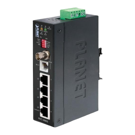
2. Hardware Description IVC-2002 The IVC-2002 provides 4 RJ-45, 1 RJ-11 and 1 BNC port for network line connection. The 4 RJ-45 ports with two different running speeds – 10Mbps and 100Mbps. It will distinguish the speed of incoming connection automatically. -
Page 12: Led Indicators For Ivc-2002
2.1.1 LED indicators for IVC-2002 The rich diagnostic LEDs on the front panel can provide the operating status of individual port and whole system. System Color Function Light Green indicate the power 1 has power Light Green indicate the power 2 has power... -
Page 13: Mode Dip Switch
2.1.2 MODE DIP Switch The Industrial Ethernet Extender provides 4 selective transmission modes. By switching the transmission modes, you can obtain a best transmission mode to suit with phone line quality or distance of connectivity. The following is the summary table of transmission setting, bandwidth and distance extensibility tested for AWG 24 (0.5mm) twisted-pair without noise and cross talk. -
Page 14: The Upper Panel
Band Plan t User can switch the Band Plan either Symmetric or Asymmetric by their own. When Symmetric is selected that provides better upstream performance, when Asymmetric is selected that provides better downstream performance. Refer to table above for details. Target SNR (Signal Noise Ratio) Margin t When fixed SNR margin is selected, the system will maintain the SNR margin at 9 dB across all usable loop length. -
Page 15: Installation
Industrial Ethernet Extender. Please check the following items: IVC-2002: The device is used for Point-to-Point connection only (Master device to Slave device) and has equipped with one RJ-11 and one BNC connectors for VDSL2 port for network link connection. -
Page 16: Ivc-2002 Bnc / Rj-11 Proper Connection
3.2 IVC-2002 BNC / RJ-11 Proper Connection PLANET Industrial Ethernet Extender has a DIP switch which can adjust to be Master or Slave mode. Connection of two PLANET Industrial Ethernet Extenders, one must be Master (CO) mode and the other one must be Slave (CPE) mode. -
Page 17: Ivc-2002 Application Connection
Equipment) which need to be placed in the wiring center (MDF room) and connect it to the telephone line system or coaxial cable system. On the other hand, need to connect an IVC-2002 converter with Master mode and connect it to the PLANET Chassis through the telephone... - Page 18 Switch 1.4km 2.4km VDSL2 IVC-2002 Master IVC-2002 Master VDSL2 VC-202A/VC-201A CPE+ IP Camera IP Camera MC-700 Chassis VDSL2 Control Center 2.4km IVC-2002 Master IP Camera IP Camera IP Camera Harbor Steel Factory IP Camera 100Base-TX UTP VDSL2 Telephone wire VDSL2...
-
Page 19: Wiring The Power Inputs
3.4 Wiring the Power Inputs The 6-contact terminal block connector on the top panel of Industrial Ethernet Extender is used for two DC redundant powers input. Please follow the steps below to insert the power wire. 1. Insert positive / negative DC power wires into the contacts 1 and 2 for POWER 1, or 5 and 6 for POWER 2. -
Page 20: Wiring The Fault Alarm Contact
3.5 Wiring the Fault Alarm Contact The fault alarm contacts are in the middle of the terminal block connector as the picture shows below. Inserting the wires, the Industrial Ethernet Extender will detect the fault status of the power failure and then forms an open circuit. The following illustration shows an application example for wiring the fault alarm contacts. -
Page 21: Mounting Installation
3.6 Mounting Installation This section describes how to install the Industrial Ethernet Extender and make connection to it. Please read the following topics and perform the procedures in the order being presented. In the installation steps below, this Manual use IGS- 801 (PLANET 8 Port Industrial Gigabit Switch) as the example. -
Page 22: Wall Mount Plate Mounting
Step 3: Please refer to following procedures to remove the Industrial Ethernet Extender from the track. Step 4: Lightly press the button of DIN-Rail for remove it from track. 3.6.2 Wall Mount Plate Mounting To install the Industrial Ethernet Extender on the wall, please follows the instructions described below. - Page 23 Step 3: Use the screws to screw the wall mount plate on the Industrial Ethernet Extender. Step 4: Use the hook holes at the corners of the wall mount plate to hang the Industrial Ethernet Extender on the wall. Step 5: To remove the wall mount plate, reverse steps above.
-
Page 24: Troubleshooting
2.4km (BNC) and 1.4km (RJ-11). Please also try to adjust the DIP switch of IVC-2002 to other SNR mode. 2. Please note you must use one IVC-2002 with Master mode and the other IVC-2002 with Slave mode, connect to each other to make it work. -
Page 25: Faq
RJ-11 Connecting and 2.4 kilometer for BNC Connecting. Q4: What is the best date rate for IVC-2002? A4: We provide the data rate of the IVC-2002 is up to: 99Mbps/63Mbps for RJ-11 Connecting and the BNC Connecting is up to 99Mbps/65Mbps (downstream / upstream) in 200 meters... - Page 26 Q6: What is SNR and what’s the effect? A6: In analog and digital communications, Signal-to-Noise Ratio, often written SNR, is a measure of signal strength relative to back- ground noise. The ratio is usually measured in decibels (dB). In digital communications, the SNR will probably cause a reduction in data speed because of frequent errors that require the source (transmitting) computer or terminal to resend some packets of data.
- Page 27 *Model Number: IVC-2002 * Produced by: Manufacturer‘s Name : Planet Technology Corp. Manufacturer‘s Address: 11F, No 96, Min Chuan Road, Hsin Tien, Taipei, Taiwan, R.O.C. is herewith confirmed to comply with the requirements set out in the Council Directive on the Approximation of the Laws of the Member States relating to Electromagnetic Compatibility Directive on (2004/108/EC).
- Page 28 This page is intentionally left blank...
Need help?
Do you have a question about the IVC-2002 and is the answer not in the manual?
Questions and answers