Sign In
Upload
Manuals
Brands
Xerox Manuals
Printer
2135DX - Phaser Color Laser Printer
Xerox 2135DX - Phaser Color Laser Printer Manuals
Manuals and User Guides for Xerox 2135DX - Phaser Color Laser Printer. We have
2
Xerox 2135DX - Phaser Color Laser Printer manuals available for free PDF download: Service Manual, Brochure
Xerox 2135DX - Phaser Color Laser Printer Service Manual (199 pages)
COLOR PRINTER
Brand:
Xerox
| Category:
Printer
| Size: 4.57 MB
Table of Contents
Users Safety Summary
4
Table of Contents
6
General Information
14
The Phaser 2135 Color Printer with Lower Tray Assembly and Lower Tray Deck
14
The Phaser 2135 Color Printer
15
CRC Life Counter Behavior
17
Printer RAM and Printer Capabilities
17
Print Engine Assemblies
18
Print Engine Circuit Boards
18
Print Engine Sensor and Switch Locations
19
Print Engine Motors, Clutches and Solenoids
20
The Image Processor Board
21
Features of the Controller Board
21
The Control Panel
22
Fault
22
On Line LED
22
Rear Panel
23
The Printer Rear Panel
23
Accessing Special Operating Modes
24
System Controller Board Leds
24
Entering Special Operating Modes
24
Paper Tray Size Sensing
25
Tray Switch Sensors and Actuators
25
Paper Size Detection
25
Specifications
26
Physical Dimensions
26
Printer Clearances
26
Functional Specifications
27
Regulatory Specifications
29
Error Codes and Messages
30
Error Messages
30
Printer Fault Messages
30
System Controller Board Diagnostic Error Codes
40
System Controller Board Fatal Error Codes
41
Troubleshooting
42
Fault History Log
42
Power on Self-Diagnostic Test
43
Print Engine Troubleshooting
44
Testing the Print Engine Controller Board
44
Verifying Printer Operation by Using Its Self-Test Print
45
Verifying Power Supply Operation
45
Measuring Power Supply Voltages
45
POWER Connector Pinout
46
Inspecting the Low-Voltage Power Supply Fuse
47
Safety Interlocks
47
Ensuring the +5 VDC Loop Is Complete
48
Door Safety Interlock Switches
48
Testing for a Shorted Motor
49
Motor and Fuser Roller Resistances
50
Media Jams and the Paper Path
51
Media-Based Problems
51
Media Problems
51
Multiple-Sheet Pick
51
The Media Skews Passing through the Paper Path
52
The Paper Tray Indicates It Is Empty When It Is Not
52
Jams
53
Paper Jams at the Paper Tray
53
Wrong Media
53
Manual Bypass Feeder Feed Jams
54
Paper Jams at the Registration Rollers
54
Paper Jams at the Transfer Belt
54
Eject Jams
55
Fuser Jams
55
Imaging Drum Up/Down Error
56
Jams in the Duplex Unit
56
No Imaging Drum Installed
56
Fan Error
57
Fuser Unit Error
57
Other Problems
58
False "No Fuser Unit Installed" Message
58
False "No Toner Cartridge Installed" Message
58
The Printer Continuously Displays "Booting" or "Initializing
58
High Temperature Error
59
Invalid Memory DIMM
59
Low Temperature Error
59
Right-Side Door Indicated Being Open When It Is Closed
59
Printing and Print Quality Problems
60
Light or Blurred Images
60
Dark, Stained Background
61
Blank Print
62
Black Stripe in Direction of Paper Travel
63
White Stripe in Direction of Paper Travel
64
Poor Fusing, Toner Offsetting
65
Repeating Defect or Voids on Print
66
Missing Characters or Voids in Print
67
Color Misalignments
68
Unexpected Colors
69
Image Is Skewed on the Paper
70
Image Is Not Centered on the Print
70
The Print Is Wrinkled
70
Macintosh Printing Problems
71
Image Never Prints
71
Image Is Rotated 90 Degrees
71
Image Prints in Black-And-White
71
Printer Isn't in the Chooser
72
Windows Printing Problems
72
Image Never Prints
72
Service Tests and Adjustments
74
Starting the Diagnostics Mode
74
Consumable Status
75
Printer Status
75
Engine Maintenance Mode Menu
75
Switch Scan Test
76
Switch Scans and the Sensor and Switches Test
79
Motor and Clutch Tests
82
Motor and Clutch Test Constraints
83
Test Printing
85
Test Print Menu
85
Consumable Count Initialization
87
Table 1: Initialization Items - Consumables
87
Consumable Counter Display
88
Consumable Counter Menu Items
88
Consumable Continuation Counter Display
89
Consumable Life-Cycle Counts
89
Adjusting Color Density and Balance
90
Interpreting the Color Balance Test Print
90
Printing a Test Page
90
Making Adjustments
91
What to Look for
91
Adjustment Recovery
92
Cleaning and Maintenance
94
Service Preventive Maintenance Procedure
94
Recommended Tools
95
Periodically Replaced Parts
95
Cleaning
96
Cleaning the LED Bar
96
Cleaning the Pickup Roller
96
Print Problem Caused by Dirty LED Lens
96
Resetting NVRAM
98
FRU Disassembly
100
About Screw Colors
100
Cabinet Panels
101
Top Cover
101
Removing the Top Cover
101
Rear Cover
102
Removing the Rear Cover
102
Front Cover
103
Left-Side Cover
104
Removing the
104
Face-Up Tray
105
Removing the Face-Up Tray
105
Right Door
106
Removing the Right Door
106
Frame Components
107
Electrical Card Cage Cooling Fan
107
Removing the Electrical Card Cage Cooling Fan
107
Front Power Supply Fan
108
Removing the Front Power Supply Fan
108
Rear Power Supply Fan
109
Removing the Rear Power Supply Fan
109
Rear Shield Plate
110
Removing the Rear Shield Plate
110
Electrical Card Cage
111
Removing the Electrical Card Cage
112
Electrical Chassis Cooling Fan
112
Printer Unit Chassis
113
Disconnecting the Registration Motor In-Line Connector (HOPFF)
113
Removing the Printer Unit Chassis
114
Top Cover Inner Frame and Front/Rear Top Cover Spring Assembly
115
Removing the Top Shield Plate
116
Front Plate Assembly
117
Removing the Left Plate Assembly
117
Electronic Boards
118
System Controller Board
118
Removing the System Controller Board
118
RAM Dimms
119
Removing the RAM Dimms
119
Hard Drive
120
Removing the Hard Drive
120
Print Engine Controller Board
121
Removing the Print Engine Controller
121
Toner Sensor Board
122
Removing the Toner Sensor Board
123
Entrance Sensor Board
124
Removing the Entrance Sensor Board
124
High Voltage Power Supply
125
Removing the High Voltage Power Supply
126
Low Voltage Power Supply
127
Removing the Low Voltage Power Supply
127
Control Panel
128
Removing the Control Panel
128
Paper Feed Components
129
Tray 1 Feed Roller and Nudger Roller
129
Removing the Feed Rollers and Nudger Roller
129
Paper-Size Sensing Board
130
Removing the Feed Roller and Nudger Roller
130
Main Feeder Assembly
131
Paper Tray Lift Motor
131
Removing the Main Feeder Assembly
131
Multi-Sheet Bypass Feeder Components
132
Multi-Sheet Bypass Feeder
132
Drive Gear
132
Multi-Sheet Bypass Feeder Sensors
132
Temperature/Humidity Sensor Board
132
Removing the Multi-Sheet Bypass Feeder
133
Paper Transport Components
134
Tray 1 Entrance Sensor Actuator
134
Removing the Tray 1 Entrance Sensor Actuator
134
Belt Entrance and Multi-Sheet Bypass Feed Sensor Actuators
135
Removing the Belt Entrance Sensor Actuator
135
Duplex Solenoid and Exit Solenoid
136
Removing the Duplex Solenoid and the Exit Solenoid
136
Transfer Belt Unit
137
Removing the Transfer Belt Unit
137
Registration Components
138
Registration Clutch
138
Removing the Registration Clutch
138
Registration Motor Assembly
139
Removing the Registration Motor Assembly
139
Registration Roller Assembly a and Drive Gear
140
Removing the Registration Roller Assembly a and Drive Gear
141
Registration Roller Assembly B
142
Removing the Registration Roller Assembly B
142
Exit Assembly and Fuser Components
143
Duplex Guide Assembly
143
Removing the Duplex Guide Assembly
144
Fuser Latching Handle (Front)
145
Fuser Latching Handle (Left)
146
Fuser Latching Handle (Rear)
147
Fuser Latching Handle (Left)
147
Fuser Exit Roller
148
Removing the Fuser Exit Roller
149
Exit Sensor Assembly
150
Removing the Exit Sensor Assembly
150
Eject Guide Assembly
151
Removing the Eject Guide Assembly
151
Stack Full Sensor
152
Removing the Stack Full Sensor
153
Drive Assembly Components
154
Main Motor Assembly
154
Imaging Drum Motor
155
Removing the Main Motor Assembly
155
Fuser Motor and Transfer Belt Drive Motor Assembly
156
Removing the Fuser Motor and Transfer Belt Drive Motor Assembly
156
Xerographic Components
157
Shutter Plate
157
Removing the Shutter Plate
157
Color Registration Sensor Assembly
158
Removing the Color Registration Sensor Assembly
158
Color Registration Solenoid
159
Removing the Color Registration Solenoid
159
LED Assembly
160
Removing an LED Assembly
160
Drum Contact Assembly
161
Removing the Drum Contact Assembly
161
Toner Sensor Actuators
162
Removing the Toner Sensor Actuators
163
Duplex Unit
164
Removing the Duplex Unit
164
FRU List
166
Using the Parts List
166
Cabinet and Top Cover Frus
168
FRU Part List of the Top Cover Inner Frame
169
Top Cover Frus
170
FRU Part List of the Printer Chassis (1 of 2)
171
Printer Chassis Frus (1 of 2)
172
Printer Chassis Frus (2 of 2)
174
Paper Tray and Paper Tray Guides Frus
176
Electrical Components Frus
177
Duplexer Unit
178
Lower Tray Assembly Frus
180
Hardware Kit
181
Gear Kit
181
Harness Kit
182
Test Prints
186
Wiring Diagram
190
Service Guide
190
Wire Routing at the Engine Controller Board
191
Details of Wiring Passthru
192
Wiring under the Top Shield Plate
193
Wiring Harnesses Route by the Imaging Drum Motors
194
Wire Routing by the Fuser and Transfer Belt Motor Unit
194
Ribbon Cable Routing under the Toner Sensor Board
195
Advertisement
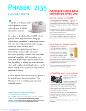
Xerox 2135DX - Phaser Color Laser Printer Brochure (4 pages)
Phaser 2135 Series COLOUR PRINTER
Brand:
Xerox
| Category:
Printer
| Size: 0.53 MB
Table of Contents
Network Printer
1
Specifications
3
Paper Handling
3
Special Features
3
Customer Support
3
Advertisement
Related Products
Xerox 2135N - Phaser Color Laser Printer
Xerox Phaser 2135DT
Xerox Phaser 2135
Xerox DocuPrint 211
Xerox Versant 2100 Press
Xerox Phaser 200E
Xerox DocuPrint 203A
Xerox WorkCentre 222
Xerox WorkCentre 228
Xerox Nuvera 200 EA
Xerox Categories
Printer
All in One Printer
Copier
Printer Accessories
Scanner
More Xerox Manuals
Login
Sign In
OR
Sign in with Facebook
Sign in with Google
Upload manual
Upload from disk
Upload from URL