Sign In
Upload
Manuals
Brands
Terex Manuals
Scissor Lifts
Genie GS-3369 DC
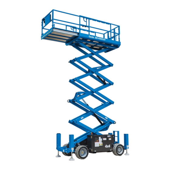
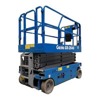
Terex Genie GS-3369 DC Manuals
Manuals and User Guides for Terex Genie GS-3369 DC. We have
3
Terex Genie GS-3369 DC manuals available for free PDF download: Service And Repair Manual, Maintenance Manual
Terex Genie GS-3369 DC Service And Repair Manual (177 pages)
Brand:
Terex
| Category:
Scissor Lifts
| Size: 11.97 MB
Table of Contents
Table of Contents
7
Introduction
2
Find a Manual for this Model
2
Read, Understand and Obey the Safety Rules and Operating Instructions in the Appropriate Operator's Manual on Your Machine
2
Serial Number Legend
4
Safety Rules
5
Table of Contents
7
Specifications
13
Machine Specifications
13
Performance Specifications
13
Hydraulic Oil Specifications
14
Hydraulic Component Specifications
16
Manifold Component Specifications
16
Battery Specifications
16
Hydraulic Hose and Fitting Torque Specifications
17
Torque Procedure
18
Observe and Obey
20
Introduction
20
Repair Procedures
20
Platform Controls
22
Circuit Board
23
Joystick
24
Platfrom Controls Alarm
25
Platfrom Emergency Stop Button
25
Platform Components
26
Platform
26
Platform Extension Deck
27
Scissor Components
29
Scissor Assembly, GS-2669 DC
30
Scissor Assembly, GS-3369 DC
33
Scissor Assembly, GS-4069 DC
37
Wear Pads
40
Lift Cylinders
42
Ground Controls
44
Software Revision Level
45
Machine Setup
46
Auxiliary Platform Lowering
47
Level Sensor - Models Without Outriggers
47
Level Sensor - Models with Outriggers
50
Service Override Mode
52
Hydraulic Pump
54
How to Test the Hydraulic Pump
54
How to Remove the Hydraulic Pump
54
How to Calibrate the Hydraulic Pump
55
Manifolds
57
Function Manifold Components
57
6-1A Function Manifold Components
61
Valve Adjustments - Function Manifold
61
How to Adjust the System Relief Valve
61
How to Adjust the Oscillate Relief Valve
63
How to Adjust the Steer Relief Valve
65
How to Adjust the Platform up Relief Valve - Models with Platform Overload
67
How to Adjust the Platform up Relief Valve - Models Without Platform Overload
76
Outrigger Manifold Components
79
Valve Coils
80
Hydraulic Tank
82
Steer Axle Components
83
Yoke Assembly
83
Steer Cylinder
85
Tie Rod
85
Oscillate Cylinder
86
Oscillate Hoses
86
Steer Angle Sensor
88
Non-Steer Axle Components
92
Drive Motors
92
Drive Hub
94
Outrigger Cylinder
95
Outrigger Components
95
Outrigger Calibration
96
Platform Overload Components
98
Platform Overload System
98
Platform Overload Recovery
102
Repair any Machine Damage or Malfunction before Operating the Machine
104
Electrocution/Burn Hazard
104
Be Sure that All Necessary Tools and Test Equipment Are Available and Ready for Use
104
Before Troubleshooting
104
Contact with Electrically Charged Circuits Could Result in Death or Serious Injury. Remove All Rings, Watches and Other Jewelry
104
Damaged or Malfunctioning Machine
104
Immediately Tag and Remove from Service a
104
Troubleshooting and Repair Procedures Shall be Completed by a Person Trained and Qualified on the Repair of this Machine
104
Introduction
104
Fault Codes
104
About this Section
105
GCON I/O Map
107
Operation Indicator Codes (OIC)
109
Diagnostic Trouble Codes (DTC)
109
Troubleshooting "HXXX" and "PXXX" Faults
110
Fault Inspection Procedure
111
Type "HXXX" Faults
113
Type "PXXX" Faults
116
Type "UXXX" Faults
118
Type "FXXX" Faults
120
Type "CXXX" Faults
123
Schematics
125
Introduction
125
Electrical Schematic Abbreviations and Wire Color Legends
126
Hydraulic Component Legend
129
Electrical Symbols Legend
130
Hydraulic Symbols Legend
131
Limit Switch Legend
132
Fuse, Ground and Platform Control Boxes
133
Fuse Box Layout, All Models
134
Ground Control Box Layout, All Models
135
Platform Control Box Layout, Models with 2 Speed Lift
138
Control Box Layout, Models with Proportional Lift
139
Electrical Schematics - ANSI / CSA
141
Electrical Schematic, GS-2669 DC and GS-3369 DC with 2 Speed Lift, (ANSI / CSA) (to Serial Number GS6915-6388)
142
Electrical Schematic, GS-2669 DC and GS-3369 DC with Proportional Lift, (ANSI / CSA) (from Serial Number GS6915-6389 to GS6915-7719)
143
Electrical Schematic, GS-2669 DC and GS-3369 DC with Proportional Lift, (ANSI / CSA) (from Serial Number GS6915-7720)
146
Electrical Schematic, GS-4069 DC with 2 Speed Lift, (ANSI / CSA) (to Serial Number GS6915-6388)
147
(ANSI / CSA) (from Serial Number GS6915-6389 to GS6915-7719)
150
Electrical Schematic, GS-4069 DC with Proportional Lift
150
Electrical Schematic, GS-4069 DC with Proportional Lift, (ANSI / CSA) (from Serial Number GS6915-7720)
150
Electrical Schematics - as / CE
153
Electrical Schematic, GS-2669 DC and GS-3369 DC with 2 Speed Lift, (as / CE) (to Serial Number GS6915-6388)
154
Electrical Schematic, GS-2669 DC and GS-3369 DC with Proportional Lift, (as / CE) (from Serial Number GS6915-6389 to GS6915-7719)
155
Electrical Schematic, GS-2669 DC and GS-3369 DC with Proportional Lift, (as / CE) (from Serial Number GS6915-7720)
158
Electrical Schematic, GS-4069 DC with 2 Speed Lift, (as / CE) (to Serial Number GS6915-6388)
159
Electrical Schematic, GS-4069 DC with Proportional Lift, (as / CE) (from Serial Number GS6915-6389 to GS6915-7719)
162
Electrical Schematic, GS-4069 DC with Proportional Lift, (as / CE) (from Serial Number GS6915-7720)
163
Hydraulic Schematics
165
Hydraulic Schematic, GS-2669 DC and GS-3369 DC with 2 Speed Lift (to Serial Number GS6915-6388)
166
Hydraulic Schematic, GS-2669 DC and GS-3369 DC with Proportional Lift (from Serial Number GS6915-6389)
167
Hydraulic Schematic, GS-4069 DC with 2 Speed Lift (to Serial Number GS6915-6388)
170
(From Serial Number GS6915-6389)
171
Hydraulic Schematic, GS-4069 DC with Proportional Lift
171
Hydraulic Schematic, GS-2669 DC and GS-3369 DC with 2 Speed Lift (to Serial Number GS6915-6388)
174
(From Serial Number GS6915-6389)
175
Advertisement
Terex Genie GS-3369 DC Service And Repair Manual (147 pages)
Brand:
Terex
| Category:
Scissor Lifts
| Size: 3.39 MB
Table of Contents
Table of Contents
7
Introduction
2
Find a Manual for this Model
2
Read, Understand and Obey the Safety Rules and Operating Instructions in the Appropriate Operator's Manual on Your Machine
2
Revision History
3
Serial Number Legend
4
Safety Rules
5
Table of Contents
7
Specifications
13
Machine Specifications
13
Performance Specifications
13
Hydraulic Oil Specifications
14
Hydraulic Component Specifications
17
Manifold Component Specifications
17
Machine Component Weights
18
Battery Specifications
18
Hydraulic Hose and Fitting Torque Specifications
19
Torque Procedure
20
Repair Procedures
22
Introduction
22
Observe and Obey
22
Platform Controls
24
Circuit Board
25
Joystick
26
Platfrom Controls Alarm
27
Platfrom Emergency Stop Button
27
Platform Components
29
Platform
29
Platform Extension Deck
30
Scissor Components
32
Scissor Assembly, GS-2669 DC
33
Scissor Assembly, GS-3369 DC
36
Scissor Assembly, GS-4069 DC
40
Wear Pads
43
Lift Cylinders
45
Height Angle Sensor
46
How to Replace the Height Angle Sensor
46
Ground Controls
48
Software Revision Level
49
Machine Setup
50
Auxiliary Platform Lowering
51
Level Sensor - Models Without Outriggers
51
Level Sensor - Models with Outriggers
54
Service Override Mode
56
Hydraulic Pump
58
How to Test the Hydraulic Pump
58
How to Remove the Hydraulic Pump
58
How to Calibrate the Hydraulic Pump
59
Manifolds
61
Function Manifold Components
61
Valve Adjustments - Function Manifold
63
How to Check the System Proportional Relief Valve
63
How to Adjust the Oscillate Relief Valve
64
How to Adjust the Steer Relief Valve
65
How to Adjust the Platform up Relief Valve
66
Outrigger Manifold Components
71
Valve Coils
72
Hydraulic Tank
74
Steer Axle Components
75
Yoke Assembly
75
Steer Cylinder
77
Tie Rod
77
Oscillate Cylinder
78
Oscillate Hoses
78
Steer Angle Sensor
80
Non-Steer Axle Components
85
Drive Motors
85
Drive Hub
87
Outrigger Components
88
Outrigger Cylinder
88
Outrigger Calibration
89
Platform Overload Components
91
How to Calibrate the Platform Overload System
91
Platform Overload Recovery
93
Down Limit Height
95
How to Calibrate the down Limit Height
95
Fault Codes
96
Introduction
96
Be Sure that All Necessary Tools and Test Equipment Are Available and Ready for Use
96
Before Troubleshooting
96
Contact with Electrically Charged Circuits Could Result in Death or Serious Injury. Remove All Rings, Watches and Other Jewelry
96
Damaged or Malfunctioning Machine
96
Electrocution/Burn Hazard
96
Immediately Tag and Remove from Service a
96
Repair any Machine Damage or Malfunction before Operating the Machine
96
Troubleshooting and Repair Procedures Shall be Completed by a Person Trained and Qualified on the Repair of this Machine
96
About this Section
97
GCON I/O Map
99
Control System Fault Codes
101
Platform Overload Fault Codes
106
Operation Indicator Codes (OIC)
111
Diagnostic Trouble Codes (DTC)
111
Troubleshooting "HXXX" and "PXXX" Faults
112
Fault Inspection Procedure
113
Type "HXXX" Faults
115
Type "PXXX" Faults
118
Type "UXXX" Faults
120
Type "FXXX" Faults
122
Type "CXXX" Faults
125
Schematics
127
Introduction
127
Electrical Schematic Abbreviations and Wire Color Legends
128
Hydraulic Component Legend
131
Electrical Symbols Legend
132
Hydraulic Symbols Legend
133
Limit Switch Legend
134
Fuse, Ground and Platform Control Boxes
135
Fuse Box Layout, All Models
136
Ground Control Box Layout
137
Platform Control Box Layout
139
Electrical Schematics
141
Electrical Schematic
142
Hydraulic Schematics
145
Hydraulic Schematic
146
Terex Genie GS-3369 DC Maintenance Manual (92 pages)
Brand:
Terex
| Category:
Scissor Lifts
| Size: 1.83 MB
Table of Contents
Models Included in this Manual
3
Glossary of Terms
4
Revision History
5
Safety Rules
7
Table of Contents
9
Performance Specifications
13
Function Speeds GS-30, GS-32, GS-46, GS-47, GS-55
13
Function Speeds GS-69, GS-84, GS-90
13
Drive Speeds
15
Torque Specifications
16
Tires and Wheels
16
Battery Specifications
17
Battery Specifications - DC and be Models
17
Engine Specifications
18
Engine Operator and Maintenance Manuals
18
Deutz Engine Models
18
Perkins Engine Models
19
Ford Engine Models
19
Kubota Engine Models
20
Kohler Engine Models
20
GM Engine Models
21
Hydraulic Specifications
22
Hydraulic Relief Valves
22
Hydraulic and Drive Hub Fluid Capacities
24
Hydraulic Oil Specifications
25
Hydraulic Hose and Fitting Torque Specifications
28
Torque Procedure
29
Maintenance Procedures
31
Introduction
31
Maintenance Schedule
33
Pre-Delivery Preparation Report
34
Scheduled Maintenance Inspection Report - Scissor Lifts
35
Programmed Maintenance Inspection Report - Scissor Lifts
36
Commissioning Procedures
37
Perform 50 Hour Service
37
Perform Engine Maintenance - 50 Hours
37
Perform 150 Hour Service
38
Quarterly Maintenance Procedures
39
Check for Open Bulletins and Owner Registration
39
Battery Inspection
40
Check the Module Tray Latch Components
43
Inspect the Battery Balancer - GS-69 DC
44
Inspect the Electrical Wiring
45
Inspect the Electrical Contactor
46
DC, Gs-69 be
46
Inspect the Voltage Inverter (if Equipped)
46
Test the Flashing Beacons (if Equipped)
48
Visual Inspection of the Hydraulic Oil
48
Inspect the Hydraulic Filters
49
Check the Exhaust System - Engine Models
50
Inspect the Fuel Tank Check Valve Venting System - GS-69 RT Gas Models
51
Test the Fuel Select Operation - Gasoline/Lpg Models
51
Check and Adjust the Engine RPM
52
Inspect the Tires, Wheels and Lug Nut Torque
55
Confirm the Proper Brake Configuration - GS-69, GS-84, GS-90
55
Test the Drive Brakes
56
Test the Drive Speed - Stowed Position
56
Test the Drive Speed - Raised Position
57
Test the down Limit Switch, Level Sensor and Pothole Limit Switches
57
Test the Platform Gate Proximity Switches and the Extension Deck Limit Switch - GS-2646 AV, GS-2646 AV35
61
Annual Maintenance Procedures
64
Check the Drive Hub Oil Level and Fastener Torque
64
Test the Function Pump - GS-69 be and GS-69 DC
65
Test the Oscillate Axle - GS-90
65
Test the down Limit Switch Descent Delay
68
And GS-90 (if Equipped)
68
Test the Platform Overload Pressure Transducer and Platform Height Sensor - GS-30, GS-32, GS-46, GS-47 (if Equipped)
70
Check the Steer Yoke King Pin Fastener Torque
72
Programmed Maintenance Procedures
73
P0-1 Inspect the Engine Air Filter - GS-69 RT
73
P0-2 Grease the Steer Yokes - GS-30, GS-32, GS-46, GS-47
74
P0-3 Deutz Engine Maintenance - under 1000 Hours
75
P0-4 Ford Engine Maintenance - under 1000 Hours
76
P0-5 Kohler Engine Maintenance - under 1000 Hours
77
P0-6 Kubota Engine Maintenance - under 1000 Hours
78
P0-7 Perkins Engine Maintenance - under 1000 Hours
79
P0-8 GM Engine Maintenance - under 1000 Hours
80
P1-1 Perform Engine Maintenance - 1000 Hours
81
P1-2 Replace the Drive Hub Oil - GS-69, GS-84, GS-90
82
P2-1 Perform Engine Maintenance - 2000 Hours
82
P2-2 Replace the Hydraulic Filters
83
P2-3 Check the Free-Wheel Configuration - GS-84 and GS-90
84
P2-4 Check the Scissor Arm Wear Pads (and Slider Blocks, if Equipped)
86
P2-5 Grease the Steer Axle Wheel Bearings - GS-69 be and GS-69 DC
89
P2-6 Test or Replace the Hydraulic Oil
90
P3-1 Perform Engine Maintenance - 3000 Hours
91
Advertisement
Advertisement
Related Products
Terex Genie GS-3369BE
Terex Genie GS-3369 BE
Terex Genie GS-3384
Terex Genie GS-3390
Terex Genie GS-3369RT
Terex Genie GS-3369
Terex GS32C-17300
Terex GS32P-148700
Terex GS32D-10100
Terex GS3216P-142676
Terex Categories
Boom Lifts
Lifting Systems
Construction Equipment
Scissor Lifts
Compact Loader
More Terex Manuals
Login
Sign In
OR
Sign in with Facebook
Sign in with Google
Upload manual
Upload from disk
Upload from URL