Sign In
Upload
Manuals
Brands
Ricoh Manuals
Printer
D012
Ricoh D012 Manuals
Manuals and User Guides for Ricoh D012. We have
2
Ricoh D012 manuals available for free PDF download: Service Manual
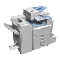
Ricoh D012 Service Manual (1209 pages)
Brand:
Ricoh
| Category:
Printer
| Size: 14.36 MB
Table of Contents
D009/D011/D012/D013/D091/D092
13
Service Manual
1
Table of Contents
13
Product Information
27
Read this First
29
Safety Notices
29
Important Safety Notices
29
Prevention of Physical Injury
29
Health Safety Conditions
29
Handling Toner
30
Laser Safety
31
Symbols and Abbreviations
32
Product Information
33
Specifications
35
Machine Configuration
36
Copier
36
Guidance for those Who Are Familiar with Predecessor Products
39
Overview
40
Component Layout
40
Paper Path
42
Drive Layout
43
Installation
45
Installation Requirements
47
Environment
48
Machine Level
49
Minimum Space Requirements
49
Power Requirements
50
Installation Flow Chart
51
Main Machine Installation
52
Accessory Check
52
Installation Procedure
54
Preliminary Procedures
54
Fire Prevention Cover
56
PCDU (Photoconductor and Development Unit)
56
Toner Bottle
59
Initialize TD Sensor and Developer
60
Paper Trays
60
Electrical Total Counter
61
Set Paper Size for Paper Trays
61
Exposure Glass Cleaner
62
Operation Instructions Holder
62
App 2 Me Setting (D091/D092 Only)
63
Settings Relevant to the Service Contract
63
Moving the Machine
65
Transporting the Machine
65
Paper Feed Unit Installation (D351)
66
Accessory Check
66
Installation Procedure
66
Lct 2000-Sheet
70
Accessory Check
70
Installation Procedure
70
1200-Sheet Lct (D353)
73
Component Check
73
Installation Procedure
74
Auto Reverse Document Feeder (B802)
76
Component Check
76
Installation Procedure
77
Platen Cover Installation (G329)
81
1-Bin Tray Unit (D389)
82
Component Check
82
Installation Procedure
82
Bridge Unit (D386)
85
Component Check
85
Installation Procedure
85
2000/3000-Sheet Finishers (B804/B805)
89
Accessory Check
89
Installation Procedure
90
Support Tray Installation
94
Punch Unit
95
Component Check
95
Installation Procedure
96
1000-Sheet Finisher (B408)
100
Accessory Check
100
Installation Procedure
104
Key Counter Bracket
104
Installation Procedure
106
Key Counter Interface Unit
106
Anti-Condensation Heater (Scanner)
108
Installation Procedure
108
Tray Heater
110
Installation Procedure
110
Tray Heater (Optional Paper Feed Unit)
112
Component Check
112
For Installing the Tray Heater in the D351 (Two-Tray Paper Feed Unit)
113
Installation Procedure
113
For Installing the Tray Heater in the D352 (LCT)
116
Hdd Option (D362, Only for D009/D012)
120
Component Check
120
Installation Procedure
121
After Installing the HDD
122
Copy Data Security Unit
123
Installation Procedure
123
User Tool Setting
124
Controller Options
126
Controller Board Slots
126
SD Slot 1, Slot 2
126
Board Slot
127
Ieee 802.11A/G, G (Wireless Lan)
128
Ieee1284
128
Installation Procedure
128
UP Mode Settings for Wireless LAN
130
SP Mode Settings for IEEE 802.11A/G, G Wireless LAN
132
Bluetooth
133
Gigabit Ethernet
134
File Format Converter
135
Postscript 3
136
Accessories
137
Installation
137
Ipds Unit
137
Before You Begin the Procedure
139
Hdd Encryption Unit
139
Installation Procedure
140
Seal Check and Removal
140
Recovery from a Device Problem
142
Before You Begin the Procedure
144
Dataoverwritesecurity Unit Type I (D362)
144
Seal Check and Removal
145
Installation Procedure
146
Browser Unit Type D
148
Installation Procedure
148
Update Procedure
150
Accessories
151
Installation
151
VM Card Type F (D377)
151
Overview
152
Printer and P/S Options (Only for D009/D012)
152
Kit Contents
154
Printer/Scanner Installation
156
Printer Enhance, Scanner Enhance Options
158
Check All Connections
163
Preventive Maintenance
165
Pm Tables
167
Replacement and Adjustment
169
General Cautions
171
Laser Unit
171
Used Toner
171
Special Tools and Lubricants
172
Lubricants
172
Special Tools
172
Exterior Covers
173
Front Door, Upper and Lower Inner Cover
173
Lower Inner Cover
173
Upper Inner Cover
173
Left Cover
174
Rear Cover
174
Right Rear Cover
175
Operation Panel
176
Paper Exit Cover
177
Inner Tray
178
Scanner -1
179
Exposure Glass
179
Monochrome Scanner Model (D009/D012)
180
Original Length/Width Sensors
180
Color Scanner Model (D011/D013/D091/D092)
181
Exposure Lamp
181
Monochrome Scanner Model (D009/D012)
183
Scanner Motor
183
Monochrome Scanner Model (D009/D012)
184
Sensor Board Unit (Sbu)
184
Color Scanner Model (D011/D013/D091/D092)
185
When Reassembling
185
Lamp Stabilizer
186
Sio (Scanner In/Out) Board
186
Scanner Hp Sensor
187
Platen Cover Sensor
188
Scanner-2
189
Front Scanner Wire
189
Reassembling the Front Scanner Wire
189
Rear Scanner Wire
192
Reassembling the Rear Scanner Wire
193
Touch Panel Position Adjustment
194
Laser Unit
196
Caution Decal Locations
196
Laser Unit
197
Laser Synchronization Detector
198
Polygon Mirror Motor
198
Laser Beam Pitch Adjustment
199
Ld Unit
199
Pcdu
202
Pcdu (Photoconductor and Development Unit)
202
Reinstallation
202
Drum
203
Re-Installation
205
Pick-Off Pawl Position Adjustment
206
Pick-Off Pawls
206
Charge Roller and Cleaning Roller
207
Drum Cleaning Blade 1
208
Re-Installation
208
ID Sensor
209
Development
210
Development Filter
210
Cleaning Procedure
211
Development Roller
211
Td Sensor
215
Transfer
216
Transfer Belt Unit
216
Transfer Belt
217
Toner Overflow Sensor
219
Transfer Belt Cleaning Blade
219
Paper Feed
220
Paper Feed Unit
220
Tray 1 and Tray 2
220
Pick-Up, Feed and Separation Rollers
221
Tray 1 and Tray 2
221
Tray Lift Motor
222
Relay, Tray Lift, Paper End and Paper Feed Sensors
223
Tray 1 and Tray 2
223
Registration Sensor
224
Reinstall the Registration Sensor
225
Fusing
226
Fusing Unit
226
Brake Pad
227
Web Roller Unit
227
Web Holder Roller and Web Rollers
228
Installing a New Web Holder Roller
230
Installing New Web Rollers
230
Pressure Roller Cleaning Roller
231
Thermostat
232
Thermistor
233
Hot Roller Strippers
234
Fusing Lamps
235
Hot Roller and Pressure Roller
236
Paper Exit
237
Fusing Exit, Paper Overflow, and Paper Exit Sensors
237
Paper Exit Unit
237
Fusing Exit Sensor
238
Junction Jam Sensor
238
Paper Exit Sensor
238
Paper Overflow Sensor
238
Paper Exit Motor
239
Duplex
240
Duplex Unit
240
Duplex Door Sensor
242
Right Door Cover
242
Duplex Entrance Sensor
243
Duplex Exit Sensor
243
Duplex/By-Pass Motor
245
Duplex Inverter Motor
246
By-Pass
248
By-Pass Paper Size Sensor
248
When Reinstalling the By-Pass Paper Size Sensor
248
By-Pass Paper End Sensor
249
By-Pass Pick-Up, Feed and Separation Roller, Torque Limiter
250
By-Pass Feed Clutch
251
Drive Area
252
Paper Feed Clutch
252
Tray 1 and Tray 2
252
Development Paddle Motor
253
Transfer/Development Motor
253
Drum Motor
254
Fusing Motor
254
Paper Feed Motor
255
Web Motor
255
Registration Motor
256
Transfer Belt Contact Motor
256
Toner Supply Motor
257
Electrical Components
258
Before Replacing the HDD Unit
258
Controller Unit
258
Hdd Unit (Standard for D011/D013/D091/D092)
258
After Installing the New HDD Unit
259
Replacement Procedure
259
Before Replacing the Controller Board in the Model Without HDD
260
Controller Board
260
Replacement Procedure
260
After Installing the Controller Board
261
When Installing the New Controller Board
261
Mother Board
262
Bicu
263
Iob
263
Psu
264
When Installing a New IOB
264
Fusing Exhaust Fan
265
High Voltage Power Supply Board
265
Controller Fan
266
When Installing the Controller Fan
266
When Installing the Fusing Exhaust Fan
266
Copy Adjustments
267
Overview
267
Printing
267
Registration - Leading Edge/Side-To-Side
267
Blank Margin
269
Main Scan Magnification
270
Parallelogram Image Adjustment
270
Scanning
271
Magnification
272
Registration: Platen Mode
272
Adf Image Adjustment
273
Registration
273
Touch Screen Calibration
274
Service Tables
275
Service Program Mode
277
Service Program Mode Operation
277
Service Mode Lock/Unlock
278
Service Program Mode Tables
279
Service Table Key
279
Service Program Mode Tables
280
Sp Tables
280
Using Sp Modes
281
Test Pattern Printing
281
Smc Print out Lists: Sp5-990
283
Nip Band Width Adjustment: Sp1-109
284
Memory Clear: Sp5-801
285
Software Reset
287
System Settings and Copy Setting Reset
288
Copier Setting Reset
289
Updating the Firmware
290
Before You Begin
290
Preparation
291
Updating Firmware
291
Firmware Update Error
292
Error Message Table
293
Handling Firmware Update Errors
293
Recovery after Power Loss
293
Nvram Data Upload/Download
295
Downloading Nvram Data (Sp5-825)
295
Uploading Nvram Data (Sp5-824)
295
Sd Card Appli Move
296
Overview
296
Use Caution When You Do the SD Card Appli Move Procedure
296
Move Exec
297
Undo Exec
298
Self-Diagnostic Mode
299
Self-Diagnostic Mode at Power on
299
Self-Diagnostic Test Flow
300
Detailed Self-Diagnostic Mode
301
Executing Detailed Self-Diagnosis
301
Using the Debug Log
302
Overview
302
Switching on and Setting up Save Debug Log
302
4-Digit Entries for Keys 1 to 10
305
Key to Acronyms
306
Recording Errors Manually
307
Retrieving the Debug Log from the HDD
307
Dip Switches
308
I/O Board: Dip Sw101
308
Troubleshooting
309
Service Call Conditions
311
Electrical Component Defects
312
Sensors
312
Switches
317
Blown Fuse Conditions
318
Energy Saving
319
Energy Save
321
Energy Saver Modes
321
Timer Settings
321
Recommendation
322
Return to Stand-By Mode
322
Energy Save Effectiveness
323
Paper Save
325
Combine Mode
325
Duplex
325
Effectiveness of Duplex/Combine Function
325
Duplex + Combine
326
D009/D011/D012/D013/D091/D092
329
Service Manual Appendices
329
D009/D011/D012/ D013/D091/D092 Appendices
331
Appendix: General Specifications
335
General Specifications
335
General
337
Power Consumption
340
Printer Controller
341
Scanner Specifications
342
Optional Equipment
343
Ardf
343
Lct 2000-Sheet
344
Two-Tray Paper Feed Unit
344
1-Bin Tray Unit
345
Lct 1200-Sheet
345
1000-Sheet Finisher
346
Bridge Unit
346
Upper Tray
346
Lower Tray
347
3000-Sheet Finisher
348
2000-Sheet Booklet Finisher
350
Punch Unit for 2000/3000-Sheet (Booklet) Finisher1-17
353
Bluetooth Specifications
354
Ieee 802.11A/G, G
354
Usb Specifications
354
Appendix: Pm Tables
355
Pm Tables
355
Mainframe
357
Ardf
363
Options
363
Lct
364
Pfu
364
Sr5020
364
2000/3000-Sheet (Booklet) Finisher
365
Bridge Unit
365
1-Bin Tray Unit
366
Appendix: Service Call Conditions
367
Service Call Conditions
367
Sc Code Descriptions
370
SC Tables: Sc1Xx
371
SC Tables: Sc2Xx
375
SC Tables: Sc3Xx
377
SC Tables: Sc4Xx
381
SC Tables: Sc5Xx
382
SC Tables: Sc6Xx
391
SC Tables: Sc7Xx
398
SC Tables: Sc8Xx
407
SC Tables: Sc9Xx
425
Appendix: Service Program Mode Tables
431
System Sp Table-1
436
System Sp Table-2
451
Sp2-XXX: Drum
451
System Sp Table-3
469
Sp3-XXX: Process
469
System Sp Table-4
472
Sp4-XXX: Scanner
472
System Sp Table-5
512
Sp5-XXX: Mode
512
System Sp Table-6
585
Sp6-XXX: Peripherals
585
System Sp Table-7
597
Sp7-XXX: Data Log
597
System Sp Table-8
616
Sp8-XXX: Data Log 2
616
Input Check
668
Copier
668
APS Original Size Detection
674
2000/3000-Sheet (Booklet) Finisher (B804, B805)
675
Options
675
1000-Sheet Finisher (B408)
679
Output Check
681
Copier
681
1000-Sheet Finisher (B408)
687
2000/3000-Sheet (Booklet) Finisher
688
Printer Service Table
691
Printer Sp Tables
691
Scanner Service Table
698
Sp Tables
698
1000-Sheet Finisher B408
703
1 Replacement and Adjustment
705
Main Pcb
705
Stapler Unit
706
Motors
707
Shift Motor
707
Stapler Motor
707
Lower Transport Motor
708
Upper Transport Motor and Exit Motor
708
Motors and Sensors
709
Preparation
709
Stack Height Sensor
710
Stapler Tray Paper Sensor
710
Lower Tray Lift Motor
711
Stack Feed-Out Motor
711
2 Troubleshooting
712
Jam Detection
712
3 Service Tables
713
Dip Switch Settings
713
4 Detailed Descriptions
714
General Layout
714
Electrical Component Layout
715
Electrical Component Description
717
Drive Layout
719
Junction Gates
720
Sort/Stack Mode
720
Staple Mode
720
Upper Tray Mode
720
Upper Tray
721
Lower Tray Up/Down Mechanisms
722
Paper Shift Mechanism
723
Jogger Unit Paper Positioning Mechanism
724
Exit Guide Plate
725
Stapler Mechanism
726
Stapler Unit Movement Mechanism
727
Paper Feed-Out Mechanism
728
Advertisement
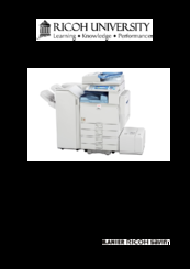
Ricoh D012 Service Manual (1165 pages)
Brand:
Ricoh
| Category:
Copier
| Size: 55.12 MB
Table of Contents
D009/D011/D012/D0
13
Table of Contents
13
Safety Notices
27
Laser Safety
28
1 Installation
33
Installation Requirements
35
Environment
36
Machine Level
37
Minimum Space Requirements
37
Power Requirements
38
Installation Flow Chart
39
Main Machine Installation
40
Installation Procedure
41
Paper Trays
46
Toner Bottle
46
Electrical Total Counter
47
Initialize Td Sensor and Developer
47
Exposure Glass Cleaner
48
Moving the Machine
49
Transporting the Machine
49
Paper Feed Unit Installation (D351)
50
Accessory Check
53
Installation Procedure
53
Lct 2000-Sheet (D352)
53
Installation Procedure
56
1200-Sheet Lct (D353)
56
Component Check
56
Installation Procedure
59
Auto Reverse Document Feeder (B802)
59
Component Check
59
Platen Cover Installation (G329)
64
1-Bin Tray Unit (D389)
65
Bridge Unit (D386)
68
2000/3000-Sheet Finishers (B804/B805)
72
Accessory Check
72
Installation Procedure
73
Punch Unit (B702)
78
Installation Procedure
79
1000-Sheet Finisher (B408)
83
Accessory Check
83
Installation Procedure
84
Key Counter Bracket
87
Installation Procedure
87
Key Counter Interface Unit
89
Installation Procedure
89
Anti-Condensation Heater (Scanner)
91
Installation Procedure
91
Tray Heater
93
Installation Procedure
93
Tray Heater (Optional Paper Feed Unit)
93
Component Check
95
Installation Procedure
95
Tray Heater (Optional Paper Feed Unit)
95
Hdd Option (D362, Only for D009/D012)
103
Component Check
103
Installation Procedure
104
Dataoverwritesecurity Unit Type I (D362)
105
Before You Begin the Procedure
105
Seal Check and Removal
105
Installation Procedure
106
Copy Data Security Unit
109
Installation Procedure
109
Hdd Encryption Unit
112
Before You Begin the Procedure
112
Seal Check and Removal
112
Installation Procedure
113
Recovery from a Device Problem
114
Browser Unit Type D
116
Installation Procedure
116
2 Preventive Maintenance
119
Pm Table - Mainframe
121
Preventive Maintenance
121
Pm Table - Options
126
3 Replacement and Adjustment
129
General Cautions
131
Laser Unit
131
Used Toner
131
Special Tools and Lubricants
132
Lubricants
132
Special Tools
132
Exterior Covers
133
Front Door, Upper and Lower Inner Cover
133
Left Cover
134
Rear Cover
134
Right Rear Cover
134
Operation Panel
135
Paper Exit Cover
136
Inner Tray
137
Scanner -1
138
Exposure Glass
138
Original Length/Width Sensors
138
Exposure Lamp
140
Scanner Motor
142
Sensor Board Unit (Sbu)
143
Lamp Stabilizer
144
Scanner Hp Sensor
145
Sio (Scanner In/Out) Board
145
Platen Cover Sensor
146
Scanner -2
147
Front Scanner Wire
147
Rear Scanner Wire
149
Touch Panel Position Adjustment
152
Laser Unit
153
Caution Decal Locations
153
Polygon Mirror Motor
154
Laser Synchronization Detector
155
Ld Unit
155
Laser Beam Pitch Adjustment
156
Pcdu
158
Drum
158
Pcdu (Photoconductor and Development Unit)
158
Pick-Off Pawls
162
Charge Roller and Cleaning Roller
163
Drum Cleaning Blade 1
164
Drum Cleaning Blade 2
164
ID Sensor
165
Development
166
Development Filter
166
Development Roller
166
Developer
167
Td Sensor
169
Transfer
170
Transfer Belt
170
Transfer Belt Unit
170
Toner Overflow Sensor
173
Transfer Belt Cleaning Blade
173
Paper Feed
174
Paper Feed Unit
174
Pick-Up, Feed and Separation Rollers
174
Relay, Tray Lift, Paper End and Paper Feed Sensors
175
Tray Lift Motor
175
Registration Sensor
176
Fusing
178
Fusing Unit
178
Web Roller Unit
178
Brake Pad
179
Web Holder Roller and Web Rollers
180
Pressure Roller Cleaning Roller
183
Thermostat
184
Thermistor
185
Fusing Lamps
186
Hot Roller and Pressure Roller
187
Paper Exit
189
Junction Jam Sensor
190
Duplex
192
Right Door Cover
194
Duplex Exit Sensor
195
Duplex/By-Pass Motor
197
By-Pass
200
By-Pass Paper End Sensor
201
By-Pass Feed Clutch
202
Drive Area
203
Transfer/Development Motor
204
Fusing Motor
205
Paper Feed Motor
206
Toner Supply Motor
207
Electrical Components
208
Controller Board
209
Replacement Procedure
210
Mother Board
211
Bicu
212
High Voltage Power Supply Board
214
Controller Fan
215
Copy Adjustments
216
Blank Margin
217
Main Scan Magnification
219
Parallelogram Image Adjustment
219
Scanning
220
Adf Image Adjustment
222
Troubleshooting
227
Sc Code Descriptions
228
Sc Tables: Sc1Xx
229
Sc Tables: Sc2Xx
233
Sc Tables: Sc3Xx
235
Sc Tables: Sc4Xx
238
Sc Tables: Sc5Xx -1
240
Sc Tables: Sc5Xx -2
245
Sc Tables: Sc6Xx
248
Sc Tables: Sc7Xx -1
254
Sc Tables: Sc7Xx -2
259
Sc Tables: Sc8Xx -1
262
Sc Tables: Sc8Xx -2
268
Sc Tables: Sc9Xx
274
Electrical Component Defects
278
Switches
282
Blown Fuse Conditions
284
Service Tables
287
Service Program Mode Tables
288
Sp1-XXX: Feed-1
289
Sp1-XXX: Feed-2
297
Sp1-XXX: Feed-3
302
Sp2-XXX: Drum-1
306
Sp2-XXX: Drum-2
314
Sp2-XXX: Drum-3
320
Sp3-XXX: Process-1
323
Sp4-XXX: Scanner-1
326
Sp4-XXX: Scanner-2
340
Sp4-XXX: Scanner-3
346
Sp5-XXX: Mode-1
361
Sp5-XXX: Mode-2
377
Sp5-XXX: Mode-3
381
Sp5-XXX: Mode-4
404
Sp5-XXX: Mode-5
420
Sp6-XXX: Peripherals-1
428
Sp7-XXX: Data Log-1
438
Sp7-XXX: Data Log-2
446
Sp8-XXX: Data Log2-1
456
Sp8-XXX: Data Log2-2
466
Sp8-XXX: Data Log2-3
475
Sp8-XXX: Data Log2-4
485
Sp8-XXX: Data Log2-5
495
Input Check - 1
502
Input Check -2
508
Output Check -1
513
Output Check -2
519
Sheet (Booklet) Finisher
520
Using Sp Modes
522
Smc Print out Lists: Sp5-990
523
Nip Band Width Adjustment: Sp1-109
524
Memory Clear: Sp5-801
525
Software Reset
527
Copier Setting Reset
528
Updating the Firmware
530
Handling Firmware Update Errors
532
Nvram Data Upload/Download
535
Sd Card Appli Move
536
Undo Exec
537
Self-Diagnostic Mode
538
Self-Diagnostic Test Flow
539
Executing Detailed Self-Diagnosis
540
Using the Debug Log
541
Recording Errors Manually
545
Retrieving the Debug Log from the Hdd
545
Dip Switches
547
Detailed Section Descriptions
551
Board Structure
555
Copy Process
559
Image Transfer
560
Scanning
561
Scanner Drive
562
Original Size Detection in Platen Mode
563
Image Processing
565
Sbu (Sensor Board Unit)
566
Auto Image Density (Ads)
568
Ipu (Image Processing Unit)
569
Image Processing Steps
570
Independent Dot Erase
571
Laser Exposure
573
Auto Power Control (Apc)
574
Around the Drum
575
Drum Cleaning
576
Drive Mechanism
577
Drum Charge
578
Charge Roller Voltage Correction
579
Correction for Paper Width and Thickness
580
ID Sensor Pattern Production Timing
581
Development
582
Developer Mixing
583
Development Bias
584
Toner Bottle Replenishment Mechanism
586
Toner Supply
586
Sensor Control Mode
587
Toner Density Control
587
Toner Supply Mechanism
587
Image Pixel Count Mode
588
Toner Near End
588
Toner End
589
Toner End Recovery
589
Toner Supply with Abnormal Sensors
589
Drum Cleaning and Toner Recycling
590
Toner Recycling
591
Pick-Up and Separation Roller Release
593
Duplex Drive
602
Inverter Mechanism
603
Duplex Operation
604
Belt Drive Mechanism
607
Transfer Belt Unit Contact Mechanism
607
Image Transfer and Paper Separation
608
Transfer Belt Charge
609
Transfer Belt Cleaning Mechanism
611
Image Fusing
612
Fusing Drive
613
Fusing Entrance Guide Shift Mechanism
614
Hot Roller Cleaning
615
Hot Roller Stripper Cleaning
616
Fusing Temperature Control
619
Cpm down System
621
Paper Feed Waiting Mode
622
Paper Exit
623
Junction Gate Mechanism
624
Exit Guide Plate and De-Curler Rollers
626
Energy Saver Modes
627
Energy Saver Mode
628
Off Mode
629
Mfp Options
630
File Format Converter (Mlb)
631
Hdd Encryption Unit (D377)
633
Specifications
639
Power Consumption
641
Machine Configuration
643
Optional Equipment -1
646
Lct 2000-Sheet
647
Bin Tray Unit
648
Sheet Finisher
649
Optional Equipment -2
651
Sheet Booklet Finisher
652
Punch Unit for 2000/3000-Sheet (Booklet) Finisher
655
1000-Sheet Finisher B408
659
1 Replacement and Adjustment
661
Main Pcb
661
Stapler Unit
662
Motors
663
Shift Motor
663
Stapler Motor
663
Lower Transport Motor
664
Upper Transport Motor and Exit Motor
664
Motors and Sensors
665
Preparation
665
Stack Height Sensor
666
Stapler Tray Paper Sensor
666
Lower Tray Lift Motor
667
Stack Feed-Out Motor
667
2 Troubleshooting
668
Jam Detection
668
3 Service Tables
669
Dip Switch Settings
669
4 Detailed Descriptions
670
General Layout
670
Electrical Component Layout
671
Electrical Component Description
673
Drive Layout
675
Junction Gates
676
Sort/Stack Mode
676
Staple Mode
676
Upper Tray Mode
676
Upper Tray
677
Lower Tray Up/Down Mechanisms
678
Paper Shift Mechanism
679
Jogger Unit Paper Positioning Mechanism
680
Exit Guide Plate
681
Stapler Mechanism
682
Stapler Unit Movement Mechanism
683
Paper Feed-Out Mechanism
684
Ardf Df3010 B802
687
1 Replacement and Adjustment
691
Covers and Tray
691
Front and Rear Cover
691
Original Tray
691
Document Feed Components
693
Feed Belt
693
Pick-Up Roller
693
Separation Roller
695
Electrical Components
696
Df Drive Board
696
Original Length Sensors and Trailing Edge Sensor
696
Original Set, Separation, Skew Correction and Scanning Entrance Sensor
697
Original Width Sensors
698
Original Exit Sensor
699
Registration Sensor
699
Cover Sensor
700
Df Position Sensor
700
Pick-Up Roller Hp and Original Stopper Hp Sensor
701
Stamp Solenoid
702
Original Feed Drive
704
Adf Feed Motor
704
Adf Inverter Motor
705
Adf Pick-Up Motor
705
Adf Transport Motor
705
2 Detailed Descriptions
707
Component Layout
707
Mechanical Component Layout
707
Electrical Component Layout
708
Drive Layout
711
Basic Operation
713
Original Size Detection
713
Mixed Original Size Mode
715
Pick-Up and Separation
716
Skew Correction
717
Original Transport and Exit
718
Slip Detection
718
Conditions for Jam Detection
720
3 Service Tables
721
Dip Switches
721
Booklet Finisher Sr3020/ Finisher Sr3030 B804/B805
725
1 Replacement and Adjustment
729
Covers
729
Exterior Covers
729
Upper Tray, End Fence
730
Main Unit
731
Upper Tray Limit Sensor, Limit Switch
731
Positioning Roller
732
Proof Tray Exit Sensor
732
Exit Guide Plate, Upper Tray Exit Sensor
733
Upper Tray Height Sensors 1, 2
733
Proof Tray Full Sensor
734
Finisher Entrance Sensor
735
Pre-Stack Tray Exit Sensor
735
Stapler Unit
736
Corner Stapler
736
Positioning Roller
737
Fold Unit
738
Fold Unit Entrance Sensor
740
Fold Unit Exit Sensor
740
Stack Present Sensor
741
Folding Horizontal Skew Adjustment (for B804 Only)
742
Fold Vertical Skew Adjustment (for B804 Only)
745
Booklet Stapler Unit
747
Booklet Stapler
747
Booklet Stapler Motor
747
2 Detailed Section Descriptions
750
Component Layout
750
General Layout
750
Proof Tray
751
Electrical Components
752
Summary of Electrical Components
756
Drive Layout
766
Junction Gates
768
Proof Mode
768
Shift Mode
768
Staple Mode
769
Pre-Stacking
770
Tray Movement Mechanism
772
Upper Tray
772
Lower Tray (B804 Only)
774
Corner Stapling
777
Stacking and Jogging
777
Stapler Movement
778
Corner Stapling
780
Booklet Stapling (B804 Only)
781
Booklet Pressure Mechanism
781
Booklet Stapling and Folding
782
Booklet Stapling and Folding Mechanisms
788
Upper Tray Output
791
Feed out
791
Feed out Stacking
792
Punch Unit B702 (for B804/B805)
793
Overview of Operation
793
Paper Position Detection
795
Punch Mechanisms
795
Punch Unit Movement
796
Punch Selection and Firing
797
Punch Hopper Mechanism
798
Finisher Jam Detection
800
Advertisement
Related Products
Ricoh D011
Ricoh D013
Ricoh D062
Ricoh D0A5
Ricoh D0BG
Ricoh D0CA
Ricoh D0C9
Ricoh D0CB
Ricoh D0BT
Ricoh D0BW
Ricoh Categories
All in One Printer
Printer
Digital Camera
Copier
Printer Accessories
More Ricoh Manuals
Login
Sign In
OR
Sign in with Facebook
Sign in with Google
Upload manual
Upload from disk
Upload from URL