Sign In
Upload
Manuals
Brands
Omron Manuals
Network Hardware
SYSMAC CJ2M-CPU3 Series
Omron SYSMAC CJ2M-CPU3 Series Manuals
Manuals and User Guides for Omron SYSMAC CJ2M-CPU3 Series. We have
11
Omron SYSMAC CJ2M-CPU3 Series manuals available for free PDF download: User Manual, Operation Manual, Connection Manual, Replacement Manual, Datasheet
OMRON SYSMAC CJ2M-CPU3 Series User Manual (640 pages)
CJ2 CPU Unit Software
Brand:
OMRON
| Category:
Software
| Size: 21.12 MB
Table of Contents
Table of Contents
13
Introduction
5
Intended Audience
5
CJ2 CPU Unit Manuals
6
Manual Structure
9
Additional Information
9
Sections in this Manual
11
Table of Contents
13
Safety Precautions
25
Application Precautions
29
Operating Environment Precautions
34
Regulations and Standards
35
Unit Versions of CJ2 CPU Units
37
Related Manuals
42
1 Overview
45
CJ2 CPU Unit Features
45
Overview of CJ2 CPU Units
45
Overview of CJ2 CPU Units
46
Overview
46
Overview
47
CJ2 CPU Unit Features
48
Basic Operating Procedure
55
2 Internal Memory in the CPU Unit
57
Overview
58
Memory Configuration
58
Built-In Flash Memory
58
Built-In Ram
58
Memory Areas and Stored Data
59
Transferring Data from a Programming Device to the CPU Unit
60
CPU Unit Operation
61
CPU Unit Operating Modes
61
CPU Unit Internal Operation
62
Overview
62
Startup Initialization
62
Cycle Time
64
Program Execution
64
I/O Refreshing
66
Processing at Power Interruptions
67
CPU Unit Operating Modes
68
Operating Modes
68
Checking the Operating Mode
69
Changing the Operating Mode
70
Operating Mode Details
74
CPU Unit Initialization
75
Overview of CPU Unit Initialization
76
CPU Unit Initial Settings
76
CPU Unit Initialization
76
Dip Switch
76
Plc Name
78
Routing Tables
79
PLC Setup
82
Creating I/O Tables
83
I/O Tables
83
Automatic Allocation
84
Manual Allocation
84
Setting Routing Tables
85
Routing Tables
85
Local Network Table
86
Relay Network Table
86
Cases in Which Routing Tables Are Required
87
Setting and Transferring Routing Tables
88
Setting Allocated DM Area Words for Special I/O Units
89
Setting Allocated DM Area Words for Special I/O Units and CPU Bus Units
89
Setting Procedure
89
CPU Bus Unit Setup Area
90
Setting Procedure
90
Understanding Programming
91
Programming
93
Programming Overview
93
Program Capacity
95
Basic Ladder Diagram Concepts
96
ST Language
98
SFC Overview
99
Tasks
101
Overview of Tasks
101
Cyclic Tasks
104
Cyclic Task Status
106
Task Control Instructions
107
Interrupt Tasks
110
External Interrupts
117
Designing Tasks
118
Flags Related to Tasks
121
Sections
128
Overview of Sections
128
Function Blocks
130
Features of Function Blocks
130
Function Block Specifications
132
Symbols
135
Overview
135
Types of Symbols
136
Variables in Function Blocks
137
Global Symbols
138
Local Symbols
138
Network Symbols
139
Network Symbols (CJ2H-CPU6@-EIP and CJ2M-CPU3@ Only)
139
Variables in Function Blocks
143
Symbol Data Types
144
Specifying Arrays
145
Automatic Address Allocation to Symbols
149
Instructions
150
Basic Understanding of Instructions
150
Instruction Conditions
151
Instruction Location and Execution Conditions
152
Instruction Variations
153
Execution Conditions
153
Specifying Operands
157
Specifying Operands
159
Data Formats
165
I/O Refresh Timing
169
Cyclic Refresh
169
Index Registers
174
What Are Index Registers
174
Using Index Registers
174
Processing Related to Index Registers
178
Monitoring Index Registers
179
Sharing Index and Data Registers between Tasks
180
Specifying Address Offsets
182
Overview
182
Examples of Address Offset Application
185
Checking Programs
186
Errors During CX-Programmer Input
186
Program Checks with the CX-Programmer
186
Debugging with the Simulator
187
Error Simulation Function
189
Program Execution Check
190
Precautions
193
Condition Flags
193
Special Program Sections
198
I\/O Memory Areas
203
I/O Memory Areas
203
I/O Memory Area Overview
204
I/O Memory Areas
204
I/O Memory Area Structure
206
Holding I/O Memory Values
208
I/O Area
210
Input Bits
210
Output Bits
212
Data Link Area
215
Synchronous Data Refresh Area
216
CPU Bus Unit Area
217
Special I/O Unit Area
218
Serial PLC Link Area
219
Devicenet Area
220
Work Area
221
Holding Area
222
Self-Maintaining Bits
222
Auxiliary Area
224
Temporary Relay Area
225
Data Memory Area
226
Extended Data Memory Area
229
Automatic Address Allocation
229
File Memory
230
Trace Memory
230
Timer Areas
233
Counter Areas
235
Task Flags
236
Index Registers
237
Data Registers
242
Condition Flags
244
Clock Pulses
246
File Operations
249
File Memory
250
File Operations
250
Types of File Memory
250
Initializing File Memory
251
Memory Card Precautions
253
Memory Card Recognition Time
253
Types of Files Stored in File Memory
255
File Types
255
Program/Network Symbol File
255
Parameter File
256
Data File
256
Comment File
257
Program Index File
257
Unit Backup File
257
Creating and Saving Files for File Memory
258
File Memory Operations
259
Types of File Memory Operations
259
Backup Restore Operation
260
File Memory Operating Procedures and File Memory Files
261
Files Automatically Transferred at Startup
261
General-Purpose Files
263
Restrictions on File Use
267
File Sizes
268
Relation between Support Software and File Memory Files
269
I\/O Allocations and Unit Settings
271
I/O Allocations
271
I/O Allocations
272
Automatic Allocation
275
Manual Allocation
279
Allocating First Words to Racks
284
I/O Table Errors and Precautions
287
Setting CPU Bus Units and Special I/O Units
290
Setting Parameters
290
Data Exchange
294
Special I/O Units
294
Fins Commands
295
Cpu Bus Units
296
Advertisement
OMRON SYSMAC CJ2M-CPU3 Series User Manual (425 pages)
CJ2 CPU Unit Hardware
Brand:
OMRON
| Category:
Processor
| Size: 9.04 MB
Table of Contents
Introduction
7
Applicable Products
7
Intended Audience
7
CJ2 CPU Unit Manuals
8
Manual Configuration
9
Hardware User’s Manual (Cat. No. W472)
9
Manual Structure
11
Page Structure
11
Special Information
11
Additional Information
11
Sections in this Manual
13
Table of Contents
15
Application Considerations
20
Suitability for Use
20
Safety Precautions
23
Definition of Precautionary Information
23
Symbols
24
Application Precautions
27
Power Supply
27
Installation
27
Wiring
28
Handling
28
External Circuits
31
Operating Environment Precautions
32
Regulations and Standards
33
Conformance to Shipbuilding Standards
34
Usage Conditions for NK and LR Shipbuilding Standards
34
Unit Versions of CJ2 CPU Units
35
Notation of Unit Versions on Products
35
Confirming Unit Versions with Support Software
35
PLC Information
35
Unit Manufacturing Information
36
Unit Versions and Programming Devices
39
Pull-Down List for PLC Models
39
Troubleshooting Problems with Unit Versions on the CX-Programmer
40
Related Manuals
41
Overview
43
Overview of CJ2 CPU Units
44
CJ2H CPU Units
45
CJ2M CPU Units
45
Overview
45
CJ2 CPU Unit Features
46
Fast, with Large Memory Capacity
46
High-Speed Processing
46
Built-In Ethernet/Ip Port
47
Built-In USB and Ethernet/Ip Ports
47
General-Purpose Networks for Support Software Interface
47
High-Speed, High-Capacity Data Links with User-Set Refresh Cycles
47
Access from Host Devices Is Enabled Using Tags
48
Network Symbols (Tags) for Flexible Support of Program Changes
48
Tag Access
48
Easier Programming
49
Synchronous Unit Operation
49
Create and Use Data Structures
50
Improved Debugging
51
Add a Serial Option Board (CJ2M-CPU3@ Only)
52
Use Pulse I/O and Interrupt Inputs (CJ2M CPU Units Only)
53
Basic Operating Procedure
54
Connecting Online to the PLC
54
I/O Allocations
54
Setting Devices and Hardware
54
General Specifications
55
Performance Specifications
56
Index
57
Function Specifications
63
Basic System Configuration and Devices
71
Expanded System Configuration
71
Basic System Configuration
72
CPU Rack
72
Expansion Racks
72
Pulse I/O Modules (CJ2M CPU Unit Only)
77
Serial Option Boards (CJ2M-CPU3@ Only)
77
CJ-Series Power Supply Units
77
Memory Cards
78
I/O Control Unit
78
End Cover
78
Maximum Number of Expansion Racks
81
Units
82
Configuration Units
84
Maximum Number of Units
84
Models of Configuration Units
84
CJ-Series Basic I/O Units
85
Input Units
85
Output Units
86
Mixed I/O Units
87
CJ-Series Special I/O Units
88
Calculating Unit Current Consumption
92
Maximum Current and Power Supplied by Power Supply Units
92
Example Calculations
93
Additional Information
94
Rack Current Consumption and Width Display
94
Calculating Power Consumption
95
Basic PLC Power Consumption (W_PLC)
95
Basic I/O Unit Power Consumption (W_IO_ONOFF)
95
Calculation Examples
96
Average Power Consumption (W)
96
Expanded System Configuration
97
Serial Communications
97
System Configuration Example
98
Communications Networks
99
Communications Network Systems
99
Communications Network Overview
100
Nomenclature and Functions
101
CPU Units
102
CPU Section
102
Nomenclature and Functions
102
CPU Unit Status Indicators
104
Memory Card Indicators
105
DIP Switch
106
Display and Indicators for Built-In Ethernet/Ip Port
108
Built-In Ethernet/Ip Section (CJ2H-CPU6@-EIP and CJ2M-CPU3@ Only)
108
Seven-Segment Display
109
Status Indicators: MS, NS, COMM, 100M, and 10M
109
Rotary Switches
111
Setting the Unit Number
111
Left/Right Dot Leds
111
Node Address Setting Switches
112
Relationship with IP Address
112
Memory Card
113
Models and Specifications
113
Operating Procedures
113
Before Using a Memory Card
114
Installing the Memory Card
114
Installing and Removing
114
Removing the Memory Card
115
Installing the Memory Card into a Personal Computer
116
Pulse I/O Modules (CJ2M CPU Unit Only)
117
Models and Specifications
117
Part Names and Functions
117
Connecting Pulse I/O Modules to the CPU Unit
118
Pulse I/O Module Detection
118
Pulse I/O Module Status Indicators
119
Mounting an Option Board
120
Serial Option Boards (CJ2M-CPU3@ Only)
120
Overview
120
Power Supply Units
121
Models and Specifications
121
Components
124
AC Input
125
DC Input
125
Lg
125
Gr
125
RUN Output (CJ1W-PA205R Only)
126
Alarm Output (CJ1W-PA205C Only)
126
Selecting a Power Supply Unit
127
Condition 1: Current Requirements
127
Current Consumption at 5 VDC
127
Current Consumption at 24 VDC
127
Basic I/O Units with Terminal Blocks
128
Interrupt Input Units
128
CJ-Series Basic I/O Units
128
Input Signal Width
129
Thirty-Two/Sixty-Four-Point Basic I/O Units with Connectors
130
Sixty-Four-Point Units
131
I/O Control Units and I/O Interface Units
132
System Configuration
132
Component Names
132
Support Software
133
4-1 Support Software
134
CX-One FA Integrated Tool Package
134
Support Software
134
CX-Programmer
135
CX-Integrator
136
Network Configurator
136
Connection Methods
137
Connecting by USB
137
Connecting Cable
137
Before Connecting
137
CX-Programmer Settings
138
Restrictions on Connecting by USB
138
Connecting by RS-232C
139
Setting the Communications Protocol
140
Connecting to Ethernet (CJ2H-CPU6@-EIP and CJ2M-CPU3@ Only)
141
Installation
145
Fail-Safe Circuits
146
Managing CPU Unit Errors
146
Managing Output Malfunctions
146
Order of Powering up the CPU Unit and Controlled System
146
Electrical Diagram
147
Emergency Stop Circuit
147
Interlock Circuits
147
Accessibility for Operation and Maintenance
148
Improving Noise Resistance
148
Installation and Wiring Precautions
148
Installation in Cabinets or Control Panels
148
PLC Orientation
149
Control Panel Installation Dimensions
150
Installation in a Control Panel
150
Routing Wiring Ducts
151
Wiring Ducts
151
Assembled Appearance and Dimensions
152
20-MM-Wide Units
153
Design Example for Width W
155
Installation Height
156
Connecting PLC Components
157
DIN Track Installation
159
DIN Track and Accessories
160
Connecting CJ-Series Expansion Racks
161
CS/CJ-Series I/O Connecting Cables
161
Cable Connections
162
Connecting the Simple Locking Connectors
162
AC Power Source
164
AC Power Supply Units
164
Isolation Transformer
164
Power Supply Wiring
164
Crimp Terminals
165
DC Power Supplies
166
Power Supply Capacity
166
Wiring in Which the 24-V Power Supply will Short
166
Grounding
167
Output Specifications
168
PLC Input Unit Wiring Example
169
External Display Device Connection Example
170
Electric Wires
171
Wiring CJ-Series Basic I/O Units with Terminal Blocks
171
Wiring Basic I/O Units with Connectors
173
Using User-Made Cables with Connector
174
Wire Size
175
Wiring Procedure
175
Connecting Pulse I/O Modules to External I/O Devices
177
Connecting Pulse I/O Modules to External I/O Devices (CJ2M CPU Unit Only)
177
Connecting to Connector-Terminal Block Conversion Units or I/O Relay Terminals
177
Connecting I/O Devices
179
DC Input Units
179
Input Devices
179
AC Input Units
180
Precautions When Connecting a Two-Wire DC Sensor
180
Output Short-Circuit Protection
182
Output Surge Current
182
Output Wiring Precautions
182
Transistor Output Residual Voltage
182
Connecting through an Ethernet Cable (CJ2H-CPU6@-EIP and CJ2M-CPU3@ Only)
183
Precautions on Laying Twisted-Pair Cable
183
Connecting the Cable
184
Ethernet Connectors
184
Control Panel Installation
186
Temperature
186
Natural Cooling
186
High Temperatures
186
Forced Air Circulation (by Fan in Closed Panel)
187
Room Cooling
187
Low Temperatures
187
Humidity
188
Vibration and Shock
188
Atmosphere
188
Electrical Environment
189
Arrangement of PLC and Units
189
PLC Installation Location
189
Input Signal Noise Countermeasures
190
Power Supply System Diagram
190
Wire Layout for the Power Supply System
190
Wiring External I/O Signal Lines
190
External Wiring
191
Wiring Routes
191
Parallel Wiring (Single Phase)
192
Partitioning Methods for Signal and Power Supply Cables
192
Wiring Methods
192
Example: Separating PLC from Power Lines
193
Other Precautions
193
Grounding Methods and Precautions
194
Principles of One-Point Grounding
194
Grounding for AC Power Supply Units
195
PLC Ground Terminals
195
Precautions When Grounding
195
Shielded Cable Ground
195
Troubleshooting
197
Omron SYSMAC CJ2M-CPU3 Series Operation Manual (464 pages)
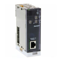
SYSMAC CS and CJ Series EtherNet/IP Units 100Base-TX 100Base-TX/10Base-T
Brand:
Omron
| Category:
Network Hardware
| Size: 19.68 MB
Table of Contents
Table of Contents
7
Operation Manual
1
About this Manual
11
Performance Data
17
Precautions
21
General Precautions
22
Intended Audience
22
Safety Precautions
22
Application Precautions
24
Operating Environment Precautions
24
Conformance to EC Directives
26
Applicable Directives
26
Concepts
26
Section 1 Overview of Ethernet/Ip
27
Overview of Ethernet/Ip
27
Ethernet/Ip Unit Features
28
Devices Required for Constructing a Network
30
Support Software Required to Construct a Network
30
Communications Services Overview
32
Fins Communications
34
Network Configurator Overview
36
Network Configurator Requirements
36
Overview
36
Precautions When Using the Network Configurator
37
Section 2 Unit Specifications
39
Unit Specifications
39
Ethernet/Ip Unit and Built-In Ethernet/Ip Port Specifications
40
General Specifications
40
Unit Specifications
40
Communications Specifications
43
Dimensions
45
Software Configuration
46
Nomenclature and Functions
47
Switch Settings
52
Selecting the Network Devices
54
Network Devices Manufactured by OMRON
54
Recommended Network Devices
54
Switching Hub Types
54
Precautions When Selecting a Switching Hub
55
Switching Hub Functions
55
Section 3 Installation and Initial Setup
59
Installation and Initial Setup
59
Overview of Initial Setup Procedures
60
Procedures
60
Switch Settings
62
CS-Series Ethernet/Ip Units
62
CJ-Series Ethernet/Ip Units and CJ2 Built-In Ethernet/Ip Port
63
Mounting to a PLC
64
Mounting to a CJ-Series PLC
64
Mounting to a CS-Series PLC
64
Mounting
65
Handling Precautions
66
Network Installation
67
Basic Installation Precautions
67
Precautions
67
Recommended Products
67
Mounting Location
69
Using Contact Outputs (Common to All Units)
69
Connecting to the Network
70
Connecting the Cable
70
Ethernet Connectors
70
Creating I/O Tables
72
Connecting Programming Devices to the PLC
72
I/O Table Overview
72
Procedure for Creating I/O Tables
72
Setting the Local IP Address
76
TCP/IP and Link Settings
78
Setting Procedure with the CX-Programmer
78
Making TCP/IP Settings with the Network Configurator
81
Tag Data Link Parameters
83
Network Configurator Setting Procedure
83
Other Parameters
87
Using Ftp
88
Using Snmp
90
Communications Test
91
Ethernet/Ip Unit or Built-In Ethernet/Ip Port Operation
91
Host Computer Operation
91
PING Command
91
Application Example
92
Section 4 Memory Allocations
93
Memory Allocations
93
Overview of Memory Allocated to the Ethernet/Ip Unit
94
CIO Area Allocations
96
Overview of the Allocated CIO Area Words
96
Details of the Allocated CIO Area Words
97
DM Area Allocations
109
Details of the Allocated DM Area Words
109
Overview of the Allocated DM Area Words
109
User Settings Area
111
Overview of the User Settings Area
111
Error Flags
113
Auxiliary Area Data
114
Read-Only Bits/Words
114
Read/Write Bits (User Settings)
115
Section 5 Determining IP Addresses
117
Determining IP Addresses
117
IP Addresses
118
Allocating IP Addresses
118
IP Address Configuration
118
Ethernet/Ip Unit IP Address Settings
119
Subnet Masks
119
IP Addresses in FINS Communications
120
Cidr
120
Specifying Nodes in FINS Communications Services
120
Pairing Addresses in Internal Tables
122
Application Examples
128
Related Products and Communications/Setting Methods
129
Pairing IP Addresses and FINS Node Addresses
131
Private and Global Addresses
132
Private and Global Addresses
133
Using a Private Address for the Ethernet/Ip Unit
133
Ethernet/Ip Unit with a Global Address
135
Section 6 Tag Data Link Functions
137
Tag Data Link Functions
137
Overview of Tag Data Links
138
Tag Data Links
138
Overview of Operation
139
Tag Data Link Functions and Specifications
141
Data Link Data Areas
142
Setting Tag Data Links
147
Starting the Network Configurator
147
Main Window
148
Tag Data Link Setting Procedure
150
Registering Devices
151
Creating Tags and Tag Sets
152
Connection Settings
167
Setting Tags Using Data Link Tool
176
Creating Connections Using the Wizard
182
Creating Connections by Device Dragging and Dropping
185
Connecting the Network Configurator to the Network
187
Downloading Tag Data Link Parameters
194
Uploading Tag Data Link Parameters
197
Verifying the Tag Data Links
198
Starting and Stopping Tag Data Links
201
Clearing the Device Parameters
202
Saving the Network Configuration File
203
Reading a Network Configuration File
204
Checking Connections
206
Changing Devices
207
Displaying Device Status
207
Ladder Programming with Tag Data Links
209
Ladder Programming Related to Tag Data Links
209
Status Flags Related to Tag Data Links
212
Section 7 Message Communications Functions
213
Message Communications Functions
213
Overview
214
FINS Message Communications
216
Explicit Message Communications
218
Message Communications Specifications
219
Message Communications Error Indications
220
Message Communications Errors
221
Advertisement
OMRON SYSMAC CJ2M-CPU3 Series Operation Manual (465 pages)
EtherNet/IP Units
Brand:
OMRON
| Category:
Network Hardware
| Size: 6.52 MB
Table of Contents
Table of Contents
7
Precautions
23
General Precautions
24
Intended Audience
24
Safety Precautions
24
Application Precautions
26
Operating Environment Precautions
26
Conformance to EC Directives
28
Applicable Directives
28
Concepts
28
Section 1 Overview of Ethernet/Ip
29
Overview of Ethernet/Ip
29
Ethernet/Ip Unit Features
30
Devices Required for Constructing a Network
32
Support Software Required to Construct a Network
32
Communications Services Overview
34
Network Configurator Overview
38
Overview
38
Network Configurator Requirements
38
Precautions When Using the Network Configurator
39
Section 2 Unit Specifications
41
Unit Specifications
41
Ethernet/Ip Unit and Built-In Ethernet/Ip Port Specifications
42
General Specifications
42
Unit Specifications
42
Communications Specifications
45
Dimensions
47
Software Configuration
49
Nomenclature and Functions
50
Switch Settings
55
Selecting the Network Devices
57
Recommended Network Devices
57
Network Devices Manufactured by OMRON
57
Switching Hub Types
57
Switching Hub Functions
58
Precautions When Selecting a Switching Hub
58
Section 3 Installation and Initial Setup
61
Installation and Initial Setup
61
Overview of Initial Setup Procedures
62
Procedures
62
Switch Settings
64
CS-Series Ethernet/Ip Units
64
CJ-Series Ethernet/Ip Units and CJ2 Built-In Ethernet/Ip Port
65
Mounting to a PLC
66
Mounting to a CS-Series PLC
66
Mounting to a CJ-Series PLC
66
Mounting
67
Handling Precautions
68
Network Installation
69
Basic Installation Precautions
69
Recommended Products
69
Precautions
69
Using Contact Outputs (Common to All Units)
71
Connecting to the Network
72
Ethernet Connectors
72
Connecting the Cable
72
Creating I/O Tables
74
I/O Table Overview
74
Connecting Programming Devices to the PLC
74
Procedure for Creating I/O Tables
74
Setting the Local IP Address
78
TCP/IP and Link Settings
80
Setting Procedure with the CX-Programmer
80
Making TCP/IP Settings with the Network Configurator
83
Tag Data Link Parameters
85
Network Configurator Setting Procedure
85
Other Parameters
89
Communications Test
93
PING Command
93
Ethernet/Ip Unit or Built-In Ethernet/Ip Port Operation
93
Host Computer Operation
93
Section 4 Memory Allocations
95
Memory Allocations
95
Overview of Memory Allocated to the Ethernet/Ip Unit
96
CIO Area Allocations
98
Overview of the Allocated CIO Area Words
98
Details of the Allocated CIO Area Words
99
DM Area Allocations
111
Overview of the Allocated DM Area Words
111
Details of the Allocated DM Area Words
111
User Settings Area
113
Overview of the User Settings Area
113
Auxiliary Area Data
116
Read-Only Bits/Words
116
Read/Write Bits (User Settings)
117
Section 5 Determining IP Addresses
119
Determining IP Addresses
119
IP Addresses
120
IP Address Configuration
120
Allocating IP Addresses
120
Ethernet/Ip Unit IP Address Settings
121
Subnet Masks
121
IP Addresses in FINS Communications
122
Cidr
122
Specifying Nodes in FINS Communications Services
122
Pairing Addresses in Internal Tables
124
Application Examples
130
Related Products and Communications/Setting Methods
131
Pairing IP Addresses and FINS Node Addresses
133
Private and Global Addresses
134
Private and Global Addresses
135
Using a Private Address for the Ethernet/Ip Unit
135
Ethernet/Ip Unit with a Global Address
137
Section 6 Tag Data Link Functions
139
Tag Data Link Functions
139
Overview of Tag Data Links
140
Tag Data Links
140
Overview of Operation
140
Tag Data Link Functions and Specifications
143
Data Link Data Areas
144
Setting Tag Data Links
149
Starting the Network Configurator
149
Tag Data Link Setting Procedure
152
Registering Devices
153
Creating Tags and Tag Sets
154
Connection Settings
169
Setting Tags Using Data Link Tool
178
Creating Connections Using the Wizard
184
Creating Connections by Device Dragging and Dropping
187
Connecting the Network Configurator to the Network
189
Downloading Tag Data Link Parameters
196
Uploading Tag Data Link Parameters
199
Verifying the Tag Data Links
200
Starting and Stopping Tag Data Links
203
Clearing the Device Parameters
204
Saving the Network Configuration File
205
Reading a Network Configuration File
206
Checking Connections
208
Changing Devices
209
Displaying Device Status
209
Ladder Programming with Tag Data Links
211
Ladder Programming Related to Tag Data Links
211
Status Flags Related to Tag Data Links
214
Omron SYSMAC CJ2M-CPU3 Series Connection Manual (68 pages)
E3Z-series IO-Link Photoelectric Sensor
Brand:
Omron
| Category:
Accessories
| Size: 3.45 MB
Table of Contents
Table of Contents
3
1 Related Manuals
4
2 Terms and Definitions
5
3 Precautions
7
4 Overview
8
5 Applicable Devices and Device Configuration
9
Applicable Devices
9
Device Configuration
10
6 Communications Settings
12
Ethernet/Ip Connection Parameters
12
IO-Link Connection Parameter
12
Slave Terminal Configuration
12
Tag Data Link Settings
13
7 IO-Link Connection Procedure
15
Work Flow
15
Slave Terminal Setup
17
PLC Setup
29
Network Settings for Host Communications
39
IO-Link Communication Status Check
51
8 Initialization Method
62
Initializing PLC
62
Initializing Slave Terminal
64
Initializing Photoelectric Sensor
65
9 Revision History
66
Omron SYSMAC CJ2M-CPU3 Series Connection Manual (62 pages)
EtherNet/IP CJ Series, OMRON Corporation Displacement Sensor
Brand:
Omron
| Category:
Computer Hardware
| Size: 2.3 MB
Table of Contents
Table of Contents
3
1 Related Manuals
4
2 Terms and Definitions
5
3 Precautions
6
4 Overview
7
5 Applicable Devices and Device Configuration
8
Applicable Devices
8
Device Configuration
9
6 Ethernet/Ip Settings
11
Parameters
11
Tag Data Link Settings
12
7 Ethernet/Ip Connection Procedure
15
Work Flow
15
Sensor Controller Setup
17
PLC Setup
28
Network Settings
38
Ethernet/Ip Communication Status Check
51
8 Initialization Method
58
Initializing PLC
58
Initializing Sensor Controller
59
9 Revision History
60
Omron SYSMAC CJ2M-CPU3 Series Replacement Manual (54 pages)
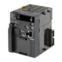
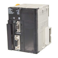
Programmable Controllers
Brand:
Omron
| Category:
Controller
| Size: 1.71 MB
Table of Contents
Related Manuals
3
Dimensions and Weights
5
Performance Data
5
Application Considerations
6
Table of Contents
7
1 Performance Specifications
8
CQM1H/CJ2M Specifications Comparison
8
CJ1M/CJ2M Specifications Comparison
9
CJ1G/CJ2M Specifications Comparison
10
2 System Configurations
11
CQM1H/CJ2M System Comfiguration Comparison
11
CJ1M/CJ1G/CJ2M System Comfiguration Comparison
13
3 Memory Area
14
CQM1H/CJ2M Memory Area Comparison
14
CJ1M/CJ1G/CJ2M Memory Area Comparison
16
4 I/O Area Allocation
18
5 Instructions
20
High-Speed Counter/Pulse Output Instruction
20
I/O Instructions
36
Model Conversion Instructions
41
6 Example of Converting Ladder Program by CX-Programmer
42
Appendix
46
Instruction Operations
46
Condition Flag Operations
49
Omron SYSMAC CJ2M-CPU3 Series Connection Manual (56 pages)
EtherNet/IP CJ Series, ZW-series Displacement Sensor
Brand:
Omron
| Category:
Computer Hardware
| Size: 2.91 MB
Table of Contents
Table of Contents
3
1 Related Manuals
4
2 Terms and Definitions
5
3 Remarks
6
4 Overview
8
5 Applicable Devices and Support Software
9
Applicable Devices
9
Device Configuration
10
6 Ethernet/Ip Connection Procedure
12
Ethernet/Ip Communications Settings
12
Work Flow
15
Setting up the Displacement Sensor
16
Setting up the PLC
24
Checking the Ethernet/Ip Communications
47
7 Initialization Method
52
Initializing the PLC
52
Initializing the Displacement Sensor
53
8 Revision History
54
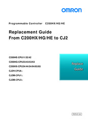
Omron SYSMAC CJ2M-CPU3 Series Replacement Manual (38 pages)
From C200HX/HG/HE to CJ2
Brand:
Omron
| Category:
Controller
| Size: 1.55 MB
Table of Contents
Table of Contents
10
Work Flow
11
Selecting the Replacement Method
12
Selecting the Model
15
Reading Data from C200HX/HG/HE
20
Converting the Program for CJ2
22
Writing Data to CJ2
24
Appendix
26
Appendix A. Instructions Converted by Change Model on CX-Programmer
26
Appendix B. Change of Unit Area Allocation
29
Appendix C. Change in PLC Settings
29
Appendix D. Change of Execution Timing Etc
29
Appendix E. Table of Input/Output Units
30
Omron SYSMAC CJ2M-CPU3 Series Replacement Manual (36 pages)
From C200HS to CJ2
Brand:
Omron
| Category:
Controller
| Size: 1.53 MB
Table of Contents
Table of Contents
10
Work Flow
11
Selecting the Replacement Method
12
Selecting the Model
15
Reading Data from C200HS
19
Converting the Program for CJ2
21
Writing Data to CJ2
23
Appendix
25
Appendix A. Instructions Converted by Change Model on CX-Programmer
25
Appendix B. Change of Unit Area Allocation
27
Appendix C. Change in PLC Settings
27
Appendix D. Change of Execution Timing Etc
27
Appendix E. Table of Input/Output Units
28
OMRON SYSMAC CJ2M-CPU3 Series Datasheet (24 pages)
CJ2 Series PLCs
Brand:
OMRON
| Category:
Controller
| Size: 2.71 MB
Table of Contents
Specifications
10
General Specifications
10
Performance Specifications
10
Ordering Information
16
Advertisement
Related Products
Omron CJ2M-CPU3 - REV 02-2010
OMRON CJ2M-CPU3 - 10-2010
Omron SYSMAC CJ2H-CPU6@-EIP
Omron CJ2H-CPU6 - REV 02-2010
OMRON CJ2H-CPU6 - 10-2010
Omron CS CJ1W-ETN21
Omron SYSMAC CJ1W-EIP21
Omron CJ1W-EIP21 - REV 02-2010
OMRON CJ1W-ETN21 - 04-2009
OMRON CJ1W-EIP21 - 10-2010
Omron Categories
Blood Pressure Monitor
Controller
Accessories
Switch
Inverter
More Omron Manuals
Login
Sign In
OR
Sign in with Facebook
Sign in with Google
Upload manual
Upload from disk
Upload from URL