Sign In
Upload
Manuals
Brands
Omron Manuals
Controller
CK5M-CPU1 1 Series
Omron CK5M-CPU1 1 Series Manuals
Manuals and User Guides for Omron CK5M-CPU1 1 Series. We have
6
Omron CK5M-CPU1 1 Series manuals available for free PDF download: Hardware User Manual, Application Manual, Startup Manual
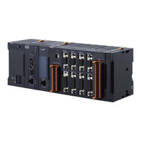
Omron CK5M-CPU1 1 Series Hardware User Manual (302 pages)
Programmable Multi-Axis Controller
Brand:
Omron
| Category:
Controller
| Size: 12.07 MB
Table of Contents
Table of Contents
8
Intended Audience
3
Applicable Products
3
Manual Structure
4
Page Structure
4
Special Information
5
Sections in this Manual
7
Table of Contents
8
Terms and Conditions Agreement
13
Warranty, Limitations of Liability
13
Application Considerations
14
Disclaimers
14
Statement of Security Responsibilities for Assumed Use Cases and against Threats
15
Safety Precautions
16
Definition of Precautionary Information
16
Symbols
16
Warning
17
Cautions
21
Precautions for Safe Use
22
Precautions for Correct Use
27
Regulations and Standards
29
Conformance to EU Directives
29
Condition for Compliance with EU Directives
29
Conformance to KC Certification
30
Conformance to UL and CSA Standards
30
Versions
31
Checking Versions
31
Related Manuals
33
Terminology
34
Revision History
35
Introduction to Motion Controllers
37
Features and System Configuration
38
Motion Controller Features
38
Introduction to the System Configurations
38
Basic Configuration
39
Support Software
39
Ethercat Network Configuration
40
Connecting to the Power PMAC IDE
50
Ethernet Network Configuration
51
CPU Unit
55
Models and Specifications
55
Part Names and Functions
58
Operation Status Indicators
59
Watchdog Output Terminal Block
60
USB Memory Device
61
Power Supply Unit
63
Models and Specifications
63
Part Names and Functions
64
Axis Interface Unit
65
Models and Specifications
65
Part Names and Functions
67
Operation Status Indicators
68
Address Switch Setting
69
Encoder Connector Specifications
69
Encoder Loss Detection
75
Pulse Input Timing Specifications for Digital Quadrature Encoder
76
Input Specifications for Sinusoidal Encoder
78
Outflag Function
80
Amplifier Connector Specifications
81
Output Method
84
Directpwm Output Method
85
Flag Connection Terminal Block Specifications
86
General Digital I/O Connection Terminal Block Specifications
91
Digital I/O Unit
98
Models and Specifications
98
Part Names and Functions
102
Operation Indicators
103
Address Switch Setting
103
Terminal Arrangement
104
I/O Data
105
Analog Input Unit
107
Models and Specifications
107
Part Names and Functions
108
Operation Indicators
109
Address Switch Setting
109
Terminal Arrangement
110
Analog Input Data
111
Input Filter
112
Encoder Input Unit
114
Models and Specifications
114
Address Switch Setting
116
Operation Indicators
116
Part Names and Functions
116
Terminal Arrangement
117
Software Settings
117
Installation
147
Power off Operation
148
Power on Operation
148
Processing at Power on and Power off
148
Fail-Safe Circuits
150
Installation in a Control Panel
152
Unit Installation
152
Connection between Units
156
Mounting to DIN Track
157
DIN Track and Accessories
159
Control Panel Installation
166
Temperature
166
Humidity
167
Atmosphere
168
Electrical Environment
168
Vibration and Shock
168
Grounding
173
Wiring
179
Applicable Wires
180
Power Supply Unit CK3W-PD048
180
Power Supply Used
180
Power Supply Wiring
180
Grounding
181
Connecting Ferrules
182
Connecting Twisted Wires/Solid Wires
182
Required Tools
182
Removing Wires
183
CPU Unit Wiring
185
Laying the Ethercat Network
185
Laying the Ethernet Network
190
Watchdog Timer Output Wiring
192
USB Memory Device Connection
195
Axis Interface Unit Wiring
196
Encoder Connector Wiring
196
Amplifier Connector Wiring
202
Flag Terminal Block/General I/O Terminal Block Wiring
204
Digital I/O Unit Wiring
211
Wiring the Terminals
211
Precautions When Connecting a Two-Wire DC Sensor
214
Precautions When Connecting to Digital Output
216
Analog Input Unit Wiring
218
Wiring the Terminals
218
Dedicated Cable
222
Encoder Connector Wiring
222
Encoder Input Unit
222
Galvo Scanner Connector Wiring
224
Laser Interface Unit
224
Laser Connector Wiring
226
Expansion Master Unit and Expansion Slave Unit Wiring
228
Troubleshooting
229
Types of Errors
230
Indicator Types
231
Procedure for Identifying Errors
231
Using the Indicators to Check Errors
231
Fatal Errors in the CPU Unit
233
Troubleshooting for Errors
233
Non-Fatal Errors in the CPU Unit
234
Initialization of CPU Unit Using USB Memory
237
Sys.status Register
238
Sys.status Register List
238
Details of Flags
239
Ethernet/Ip Connection Status Codes and Troubleshooting
249
Appendices
257
A-1 General Specifications
259
A-2 Dimensions
260
A-2-1 CPU Unit
260
Axis Interface Unit
261
Power Supply Unit
261
CK3W-MD and CK3W-AD Units
262
CK3W-ECS and CK3W-GC Units
263
Expansion Master Unit and Expansion Slave Unit
264
A-2-7 End Cover
265
Restrictions on Using the NX-Series Ethercat Coupler Unit
266
OMRON Servo Drive Connection Example
267
A-5 Version Information
268
A-6 How to Read the Lot Number
269
A-7 Supported CIP Objects
270
A-7-1 Identity Object (Class ID: 01 Hex
270
Assembly Object (Class ID: 04 Hex
271
TCP/IP Interface Object (Class ID: F5 Hex
272
Ethernet Link Object (Class ID: F6 Hex
273
A-8-1 Gate3[I].Serialencctrl (Serial Encoder Control
277
Software Reference of Encoder Input Unit
277
Gate3[I].Chan[J].Serialenccmd (Serial Encoder Command
280
Gate3[I].Chan[J].Serialencena (Serial Encoder Enable
280
Gate3[I].Chan[J].Serialencdataa (Serial Encoder Data a
283
Gate3[I].Chan[J].Serialencdatab (Serial Encoder Data B
284
Gate3[I].Chan[0].Status (Internal Memory Error Detection
287
Gate3[I].Serialencctrl (Control Register
289
Software Reference of Laser Interface Unit
289
Gate3[I].Chan[J].Dac[0] (Setting of Command Position and Control Command
290
Gate3[I].Chan[J].Dac[1] (Setting of Command Position Compensa- Tion Value
291
Gate3[I].Chan[J].Serialencdataa (Command Position after Interpola- Tion, Reception Data
291
Gate3[I].Chan[J].Serialencdatab (Status Data
292
Gate3[I].Chan[0].Compa (PWM Output Setting
293
Gate3[I].Chan[1].Compa (PWM Output Delay Setting
294
Gate3[I].Chan[2].Compa (PWM Output Pulse Count
294
A-9-10 Gate3[I].Chan[1].Compb (TCR Output Comparison Table Setting
295
A-9-11 Gate3[I].Chan[2].Compb (TCR Output Control Register
295
Gate3[I].Chan[0].Compb (TCR Output Command Distance Setting
295
A-9-12 Gate3[I].Chan[3].Compb (TCR Output Status Register
296
A-9-13 Gate3[I].Chan[0].Status (Internal Memory Error Detection
296
Advertisement
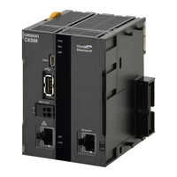
Omron CK5M-CPU1 1 Series Application Manual (90 pages)
Programmable Multi-Axis Controller
Brand:
Omron
| Category:
Controller
| Size: 8.44 MB
Table of Contents
Table of Contents
4
Precautions
6
Symbols
6
Related Manuals
7
Terms and Definitions
8
Revision History
9
About this Guide
11
Introduction
12
Target Device and Device Configuration
13
Device Configuration
14
Connection Procedures
17
Work Flow
18
Controller Setting Preparations
20
Creation of a New Project
20
Controller Initial Setting
21
Setup of the MOTF
23
Programming
23
Determination of Filter's Coefficients
29
Setup of the Motors and Encoder
37
Wiring Devices
37
Programming
38
Tuning of the Current Loop
42
Establishment of the Phase Reference
44
Open-Loop Testing
45
Position Loop Auto-Tuning
46
Position Loop Interactive Tuning
47
Tuning of the y Axis
51
Confirmation of the Tuning Results
52
Setup of Overtravel Limit Switches and Home Positions
55
Wiring of Devices
55
Programming
55
Confirmation of the Settings (Overtravel Limit Switches)
57
Setup of Home Positions
58
Setup of the Galvo Scanner
60
Wiring of Devices
60
Programming
61
Setup of Control Commands
63
Confirmation of the Settings
65
Verification of the MOTF on the Actual Machine
66
Setup of the Laser Oscillator
67
Wiring of Devices
67
Guide Laser Output
67
Programming
69
Setup of the Laser Oscillator
72
Confirmation of the Settings
74
Globaldefinitions.pmh
78
Motiononthefly.pmh
79
Motorcontrol.pmh
80
Sensorcontrol.pmh
83
Galvano.pmh
84
Lasercontrol.pmh
86
Tcrconfigurations.pmh
87
Omron CK5M-CPU1 1 Series Startup Manual (76 pages)
Programmable Multi-Axis Controller
Brand:
Omron
| Category:
Servo Drives
| Size: 3.91 MB
Table of Contents
Table of Contents
3
Related Manuals
4
Terms and Definitions
5
Precautions
6
Overview
7
Applicable Devices and Device Configuration
8
Applicable Devices
8
Device Configuration
9
Ethercat Connection Procedure
10
Workflow
10
Preparation for the Controller Setup
12
Installation of ESI Files
17
Ethercat Communications Setup
18
Controller Settings
26
Appendix Saving and Loading a Project
37
Saving a Project
37
Loading and Downloading a Project
39
Appendix Using Safety Function
42
Device Configuration
42
Workflow
42
Ethercat Coupler Unit Settings
44
Preparation for the Controller Setup
56
Installation of ESI Files
56
Ethercat Communications Setup
56
Controller Settings
67
Appendix Troubleshooting
68
Factors Causing Ethercat Communications to be Unavailable, and Corrective Actions
68
How to Check for Errors
69
Appendix Ecat[I] Structure Elements
73
Revision History
74
Advertisement
Omron CK5M-CPU1 1 Series Startup Manual (52 pages)
Programmable Multi-Axis Controller
Brand:
Omron
| Category:
Servo Drives
| Size: 1.98 MB
Table of Contents
Table of Contents
3
Related Manuals
4
Terms and Definitions
5
Precautions
6
Overview
7
Applicable Devices and Device Configuration
8
Applicable Devices
8
Device Configuration
9
Ethercat Connection Procedure
10
Workflow
10
Preparation for the Controller Setup
12
Installation of ESI Files
17
Ethercat Communications Setup
18
Controller Settings
27
Appendix Saving and Loading a Project
39
Saving a Project
39
Loading and Downloading a Project
41
Appendix Troubleshooting
44
Factors Causing Ethercat Communications to be Unavailable, and Corrective Actions
44
How to Check for Errors
45
Appendix Ecat[I] Structure Elements
48
Revision History
49
Omron CK5M-CPU1 1 Series Startup Manual (42 pages)
Programmable Multi-Axis Controller
Brand:
Omron
| Category:
Controller
| Size: 1.5 MB
Table of Contents
Table of Contents
3
Related Manuals
4
Terms and Definitions
5
Precautions
6
Overview
7
Applicable Devices and Device Configuration
8
Applicable Devices
8
Device Configuration
9
Ethercat Connection Procedure
10
Workflow
10
Preparation for the Controller Setup
11
Installation of ESI Files
16
Ethercat Communications Setup
17
Controller Settings
24
Appendix Saving and Loading a Project
29
Saving a Project
29
Loading and Downloading a Project
31
Appendix Troubleshooting
34
Factors Causing Ethercat Communications to be Unavailable, and Corrective Actions
34
How to Check for Errors
35
Appendix Ecat[I] Structure Elements
38
Revision History
39
Omron CK5M-CPU1 1 Series Startup Manual (28 pages)
Serial Encoder BiSS-C/EnDAT 2.1/2.2/1S Motor
Brand:
Omron
| Category:
Media Converter
| Size: 1.63 MB
Table of Contents
Table of Contents
4
Precautions
5
Related Manuals
6
Terms and Definitions
7
Revision History
8
About this Guide
9
Introduction
10
Intended Audience
10
Target Device and Device Configuration
11
Device Configuration
12
Serial Encoder Connection Procedures
13
Work Flow
14
Controller Setting Preparations
15
Creation of a New Project
15
Controller Initial Setting
16
Serial Encoder Wiring
18
Various Controller Settings and Checking Operation
19
Serial Encoder Status and Error Information
23
Biss-C Encoder Error Information
24
Endat2.2 Encoder Status and Error Information
25
Motor Encoder Status and Error Information
26
Advertisement
Related Products
Omron CK5M Series
Omron CK5W-EXS01
Omron CK3E-1210
Omron CK3W-AD 100 Series
Omron CK3W-PD048
Omron CK3W-AX1414N
Omron CK3W-AX1313P
Omron CK3W-EXM01
Omron CK3M-CPU 1 Series
Omron CK3W-AX Series
Omron Categories
Blood Pressure Monitor
Controller
Accessories
Switch
Inverter
More Omron Manuals
Login
Sign In
OR
Sign in with Facebook
Sign in with Google
Upload manual
Upload from disk
Upload from URL