Sign In
Upload
Manuals
Brands
MOTOROLA Manuals
Portable Radio
JT-1000 - SERVICE
MOTOROLA JT-1000 - SERVICE Manuals
Manuals and User Guides for MOTOROLA JT-1000 - SERVICE. We have
4
MOTOROLA JT-1000 - SERVICE manuals available for free PDF download: User Manual, Service Manual
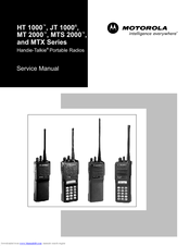
MOTOROLA JT-1000 - SERVICE Service Manual (170 pages)
MTX Series
Brand:
MOTOROLA
| Category:
Portable Radio
| Size: 9.74 MB
Table of Contents
Table of Contents
5
List of Tables
10
Model Numbering System
12
Model Charts Model Programming, Flashing, and Cloning
13
Model Charts General Description
13
Programming, Flashing, and Cloning
13
MODEL CHART, Conventional Systems Radios (HT 1000 Models)
14
MODEL CHART, Conventional Systems Radios (JT 1000 and MT 2000 Models)
15
MODEL CHART, Private Systems Radios (MTS 2000 Models)
16
MODEL CHART, Shared Systems Radios
17
MTX 9000 Models)
17
List of Antennas
18
List of Batteries
18
Maintenance Specifications for VHF Radios
19
Maintenance Specifications for UHF Radios
19
Maintenance Specifications for 800Mhz Radios
20
Maintenance Specifications for 900Mhz Radios
20
Glossary
21
1 Introduction
23
2 Test Equipment, Service Aids, and Tools
25
Recommended Test Equipment
25
Table 1 Recommended Test Equipment
25
Service Aids and Recommended Tools
26
Field Programming
26
Table 2 Service Aids
27
Table 3 Recommended Service Tools
28
3 Transceiver Performance Testing
29
General
29
Setup
29
Test Mode
29
Table 4 Equipment Initial Control Settings
29
Table 5 Test Environments, HT 1000/JT 1000 Radios
30
Table 6 Test Frequencies, HT 1000 / JT 1000
31
Table 7 Test Environments, MT 2000, MTS 2000, and MTX Series Radios
34
Table 8 Test Frequencies, MT 2000, MTS 2000, and MTX Series Radios
34
Table 9 Receiver Performance Checks
35
Table 10 Transmitter Performance Checks
36
4 Error-Code Displays
37
Power-Up Display Codes
37
Table 11 Power-Up Display Codes
37
Operational Display Codes
38
Table 12 Operational Display Codes
38
5 Radio Alignment Procedure
39
General
39
Reference Oscillator Alignment
41
Table 13 Reference Oscillator Alignment
41
Front-Endpre-Selector VHF/UHF Only)
42
Rated Audio
42
Table 14 Standard Test Modulation (1 Khz Tone)
42
Squelch
43
Transmitter Power
43
Transmit Deviation Balance (Compensation)
44
Table 15 Transmit Power Setting
44
Transmit Deviation Limit
45
Transmit Deviation Limit Reference
45
Table 16 Transmit Deviation Limit
45
VCO Crossover Frequency
46
Table 17 Transmit Deviation Limit Reference
46
Signalling Deviation
49
Alignment Procedure Conclusion
50
Table 18 Signalling Deviation
50
6 Disassembly and Reassembly
51
General
52
Disassembly to Board Level
52
Disassembly of Control Top
56
Disassembly of Front Cover Assembly
57
Reassembly
58
7 Maintenance
63
Introduction
63
Preventive Maintenance
63
Safe Handling of CMOS Devices
64
Repair Procedures and Techniques
64
8 Exploded Views
73
Basic Radios and Basic Radios with Option Mate Optional
74
Top-Display Radios
75
Keypad Radios
76
Uni-Board Radios
77
9 Component Location Diagrams, Parts Lists, and Schematic Diagrams
79
Introduction
79
NUD7091B, NUD7092B, NUD/PMUD7095B, and NUD7096B VHF (136-178Mhz) TRANSCEIVER BOARDS' PARTS LIST and COMPONENT LOCATION DIAGRAMS
84
Electrical Parts List, VHF Transceivers NUD7091B, NUD7092B, NUD/PMUD7095B, NUD7096B
85
BOARDS' SCHEMATIC DIAGRAM (Sheet 1 of 2)
86
BOARDS' SCHEMATIC DIAGRAM (Sheet 2 of 2)
87
NUE7265B, NUE7266B, NUE/PMUE7272B, and NUE7274B UHF (403-470Mhz) TRANSCEIVER BOARDS' PARTS LIST and COMPONENT LOCATION DIAGRAMS
88
Nue7274B
89
BOARDS' SCHEMATIC DIAGRAM (Sheet 1 of 2)
90
NUE7265B, NUE7266B, NUE/PMUE7272B, and NUE7274B UHF (403-470Mhz) TRANSCEIVER BOARDS' SCHEMATIC DIAGRAM (Sheet 2 of 2)
91
NUE7267B, NUE7268B, NUE/PMUE7273B, and NUE7275B UHF (450-520Mhz) TRANSCEIVER BOARDS' PARTS LIST and COMPONENT LOCATION DIAGRAMS
92
Nue7275B
93
NUE7267B, NUE7268B, NUE/PMUE7273B, and NUE7275B UHF (450-520Mhz) TRANSCEIVER BOARDS' SCHEMATIC DIAGRAM (Sheet 1 of 2)
94
NUE7267B, NUE7268B, NUE/PMUE7273B, and NUE7275B UHF (450-520Mhz) TRANSCEIVER BOARDS' SCHEMATIC DIAGRAM (Sheet 2 of 2)
95
NUF6410B/C, NUF6498B/C, NUF6500B/C and NUF6501C (800Mhz) TRANSCEIVER BOARDS' PARTS LIST and COMPONENT LOCATION DIAGRAMS
96
Electrical Parts List, Transceivers (800Mhz) NUF6410B/C, NUF6498B/C, NUF6500B/C and NUF6501C
97
NUF6410B/C, NUF6498B/C, NUF6500B/C and NUF6501C (800Mhz) TRANSCEIVER BOARDS' SCHEMATIC DIAGRAM (Sheet 1 of 2)
98
NUF6410B/C, NUF6498B/C, NUF6500B/C and NUF6501C (800Mhz) TRANSCEIVER BOARDS' SCHEMATIC DIAGRAM (Sheet 2 of 2)
99
NUF/PMUF6500D, NUF/PMUF6533A and NUF/PMUF6410D (800Mhz) TRANSCEIVER BOARD PARTS LIST and COMPONENT LOCATION DIAGRAMS
100
Pmuf6410D
101
NUF/PMUF6500D, NUF/PMUF6533A and NUF/PMUF6410D (800Mhz) TRANSCEIVER BOARDS' SCHEMATIC DIAGRAM (Sheet 1 of 2)
102
NUF/PMUF6500D, NUF/PMUF6533A and NUF/PMUF6410D (800Mhz) TRANSCEIVER BOARDS' SCHEMATIC DIAGRAM (Sheet 2 of 2)
103
NUF6499B/C and NUF6502B/C (900Mhz) TRANSCEIVER BOARDS' PARTS LIST and COMPONENT LOCATION DIAGRAMS
104
Electrical Parts List, Transceivers (900Mhz) NUF6499B/C and NUF6502B/C
105
(Sheet 1 of 2)
106
(Sheet 2 of 2)
107
Diagrams
108
Electrical Parts List, Transceiver (900Mhz) NUF/PMUF6499D
109
NUF/PMUF6499D (900Mhz) TRANSCEIVER BOARDS' SCHEMATIC DIAGRAM (Sheet 1 of 2)
110
NUF/PMUF6499D (900Mhz) TRANSCEIVER BOARDS' SCHEMATIC DIAGRAM (Sheet 2 of 2)
111
Ncn6145A/C, Ncn6146A, Ntn7089C, Ncn6129C, Ncn6138A, Ncn6140A/B, Ncn6141A
112
Diagrams
112
Ncn6129C, Ncn6138A, Ncn6140A/B, Ncn/Pmcn6140C, Ncn6141A, Ncn6145A/C
114
Schematic Diagram
114
Ncn6129C, Ncn6138A, Ncn6140A/B, Ncn/Pmcn6140C, Ncn6141A, Ncn6145A/C, Ncn6146A, Ntn7089C Controller Board Digital Section Schematic Diagram
115
Ncn6129C, Ncn6138A, Ncn6140A/B, Ncn/Pmcn6140C, Ncn6141A, Ncn6145A/C, Ncn6146A, Ntn7089C and Pmcn6140C Controller Board Top-Level Schematic
116
Ncn6129C, Ncn6138A, Ncn6140A/B, Ncn/Pmcn6140C, Ncn6141A, Ncn6145A/C, Ncn6146A, Ntn7089C Controller Board Power Section Schematic Diagram
117
Ncn6147A/B, Ncn6150A/B, Ntn7091D, Ntn7620E, Pmcn6147B and Pmcn6150B Controller Board' Parts List and Component Location Diagram
118
Electrical Parts List, Controllers NCN6147A/B, NCN6150A/B, NTN7091D, NTN7620E
119
Pmcn6147B, Pmcn6150B
119
Ncn6147A/B, Ncn6150A/B, Ntn7091D, Ntn7620E, Pmcn6147B and Pmcn6150B Controller Board Analog Section Schematic Diagram
120
Ncn6147A/B, Ncn6150A/B, Ntn7091D, Ntn7620E, Pmcn6147B and Pmcn6150B Controller Board Digital Section Schematic Diagram
121
Ncn6147A/B, Ncn6150A/B, Ntn7091D, Ntn7620E, Pmcn6147B and Pmcn6150B Controller Board Top-Level Schematic
122
Ncn6147A/B, Ncn6150A/B, Ntn7091D, Ntn7620E, Pmcn6147B and Pmcn6150B Controller Board Power Section Schematic Diagram
123
Ntn7512D/E, Ntn7513E, Ntn7857D/E and Ntn7858D/Econtroller Boards' Parts List and Component Location Diagrams
124
UHF and 800Mhz Radios NTN7858D/E Top/No Display 900Mhz Hear Clear Radios
125
Ntn7512D/E, Ntn7513E, Ntn7857D/E and Ntn7858D/Econtroller Board Analog Section Schematic Diagram
126
Ntn7512D/E, Ntn7513E, Ntn7857D/E and Ntn7858D/Econtroller Board Digital Section Schematic Diagram
127
Schematic
128
Ntn7512D/E, Ntn7513E, Ntn7857D/E and Ntn7858D/Econtroller Board Power Section Schematic Diagram
129
Ncn6106C, Ncn/Pmcn6153A/B, and Ncn/Pmcn6176A Controller Boards' Parts List and Component Layout Diagrams
130
Electrical Parts List, Controllers NCN6106C, NCN/PMCN6153A/B, NCN/PMCN6176A
131
Ncn6106C , Ncn/Pmcn6153A/B, Ncn/Pmcn6176A Controller Board Analog Section Schematic Diagram
132
Ncn6106C, Ncn/Pmcn6153A/B and Ncn/Pmcn6176A Controller Board Digital Section Schematic Diagram
133
Schematic
134
Ncn6106C, Ncn/Pmcn6153A/B and Ncn/Pmcn6176A Controller Board Power Section Schematic Diagram
135
Front Cover Display Flex and Controls Flex Schematic Diagrams
136
10 Replacement Parts Ordering
137
Introduction
137
Mail Orders
137
Motorola Online
137
FAX Orders
138
Parts Identification
138
Product Customer Service
138
Telephone Orders
138
Appendix A Table 1. MTS 2000 Single Key Secure Module I/O Definition
140
Appendix A Table 2. Key Variable Loader
142
Appendix A Table 3 - Secure Deviation
145
Appendix A Table 4. RSS Secure Parameters
148
Appendix B Table 1. HT 1000 Models
150
Appendix B Table 2. JT 1000 Models
152
Appendix B Table 3. MT 2000 Models
152
Appendix B Table 4. MTS 2000 Models
155
Appendix B Table 5. MTX Series Models
161
Advertisement
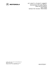
Motorola JT-1000 - SERVICE User Manual (205 pages)
Brand:
Motorola
| Category:
Portable Radio
| Size: 0.48 MB
Table of Contents
Computer Software Copyrights
2
Table of Contents
5
1 Introduction
7
Using this Manual
7
Prerequisites
8
Equipment Checklist
9
Assembling the Hardware
10
What's on the RSS Diskettes
12
Installing the RSS
12
The Banner Screen
14
Anatomy of a Menu
15
Navigating through the RSS Menus
16
Anatomy of a Screen
17
Changing a Field Value
18
Complete Menu Mapping at a Glance
19
Main Menu
21
Setup Computer Configuration
23
Organizing Your Hard Disk
25
Exiting the RSS
26
2 Service Menu Functions
27
Servicing the Radio Using the RSS
27
Menu Map
27
Service Menu
28
Transmit Alignment Menu
30
Reference Frequency Alignment
32
Transmit Power Alignment
34
Transmit Deviation Balance (Compensation) Alignment
36
Transmit Deviation Limit Alignment
38
Transmit Deviation Limit Alignment: Reference Softpot
40
Transmit VCO Crossover Alignment
42
Receiver Alignment Menu
43
Front-End Filter Alignment (VHF and UHF)
44
Rated Audio Alignment (Carrier Squelch)
46
Squelch Alignment (25/30 Khz)
47
Squelch Alignment (20 Khz)
49
Squelch Alignment (12.5 Khz)
50
Receiver VCO Crossover Alignment
51
Signalling Alignment Menu
52
Transmit Deviation Limit Alignment: MDC-1200 Signalling
54
Transmit Deviation Limit Alignment: DTMF Signalling
55
Transmit Deviation Limit Alignment: Single Tone Signalling
56
Test Mode Alignment
57
Controller Board Initialization
59
3 Get/Save/Program Menu Functions
61
Menu Map
61
Get/Save/Program Menu
62
Read Data from Radio (Requires RIB)
64
Get Workspace Data from Archive File
65
Clone (Copy) Data to Another Radio
67
Save Workspace Data to Archive File
70
Program Radio Codeplug (Requires RIB)
71
4 Change/View Menu Functions
73
Menu Map
73
Change/View Menu
74
Radio Information Screen
76
Radio Configuration Menu
77
Radio System Configuration
79
VISAR Configuration Options ( Models with Display Only )
83
JT1000 Configuration Options
86
Side Button Configuration ( HT 1000 "A" Revision Models Only )
89
Side Button Configuration ( VISAR Only )
91
Side Button Configuration ( HT 1000 "B" and JT1000 Models )
94
Alert Tone Configuration
97
Option•Mate Configuration ( HT 1000 "C" or Later Models Only )
100
Mode Switch Position Assignment (HT/JT1000 Only)
102
Signalling Options
105
Quik-Call II Options
106
MDC Configuration
108
Repeater Access Configuration
114
MDC Options
115
STAR Configuration
119
STAR Options
123
ATIS Configuration
125
Singletone Options (JT1000, VISAR and HT 1000 "B" or Later Models Only)
129
DTMF Phone List (JT1000 and VISAR Models Only)
131
DTMF Configuration List ( VISAR Models with Keypad Only )
133
DTMF Phone List (HT 1000 "B" or Later Models Only)
136
DTMF Configuration ( HT 1000 "B" or Later and JT1000 Models Only )
138
Scan List
140
Scan Configuration
141
Channel Configuration
146
Channel Options
157
5 Print Menu Functions
163
Menu Map
163
Print Menu
164
Print Service Menu
165
Print Transmit Service Menu
166
Print Receive Service Menu
167
Print Codeplug Menu
168
Print Codeplug Configuration Menu
169
Appendix A - Computer-To-Radio Communication Error Codes
173
Appendix B - TPL Frequencies and Codes
175
Appendix C - DPL Codes
177
Appendix D - Quik-Call II Frequencies and Codes
179
Appendix E - HT/JT1000/VISAR RSS Cross Reference
181
Glossary
191
Index
197
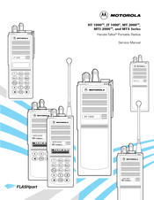
Motorola JT-1000 - SERVICE Service Manual (90 pages)
Brand:
Motorola
| Category:
Portable Radio
| Size: 1.78 MB
Table of Contents
Radio Frequency (RF) Operational Characteristics
4
Radio Operation and EME Exposure
4
Operational Warnings
6
Operational Cautions
7
Important Safety Information: Intrinsically Safe Radios
7
Table of Contents
13
List of Tables
16
Model Numbering System
18
Model Charts Model Programming, Flashing, and Cloning
19
Model Charts General Description
19
Programming, Flashing, and Cloning
19
MODEL CHART, Conventional Systems Radios (HT 1000 Models)
20
MODEL CHART, Conventional Systems Radios (JT 1000 and MT 2000 Models)
21
MODEL CHART, Private Systems Radios (MTS 2000 Models)
22
MODEL CHART, Shared Systems Radios
23
MTX 9000 Models)
23
List of Antennas
24
List of Batteries
24
Maintenance Specifications for VHF Radios
25
Maintenance Specifications for UHF Radios
25
Maintenance Specifications for 800Mhz Radios
26
Maintenance Specifications for 900Mhz Radios
26
Glossary
27
Introduction
29
Safety and General Information
30
Electromagnetic Interference/Compatibility
31
Test Equipment, Service Aids, and Tools
31
Recommended Test Equipment
31
Table 1 Recommended Test Equipment
31
Safety and General
32
Service Aids and Recommended Tools
32
Field Programming
32
Table 2 Service Aids
33
Table 3 Recommended Service Tools
34
Transceiver Performance Testing
35
General
35
Setup
35
Test Mode
35
Table 4 Equipment Initial Control Settings
35
Table 5 Test Environments, HT 1000/JT 1000 Radios
36
Table 6 Test Frequencies, HT 1000 / JT 1000
37
Table 7 Test Environments, MT 2000, MTS 2000, and MTX Series Radios
40
Table 8 Test Frequencies, MT 2000, MTS 2000, and MTX Series Radios
40
Table 9 Receiver Performance Checks
41
Table 10 Transmitter Performance Checks
42
Error-Code Displays
43
Power-Up Display Codes
43
Table 11 Power-Up Display Codes
43
Operational Display Codes
44
Table 12 Operational Display Codes
44
Radio Alignment Procedure
45
General
45
Reference Oscillator Alignment
47
Table 13 Reference Oscillator Alignment
47
Front-End Pre-Selector (VHF/UHF Only)
48
Rated Audio
48
Table 14 Standard Test Modulation (1 Khz Tone)
48
Squelch
49
Transmitter Power
49
Transmit Deviation Balance (Compensation)
50
Table 15 Transmit Power Setting
50
Transmit Deviation Limit
51
Transmit Deviation Limit Reference
51
Table 16 Transmit Deviation Limit
51
VCO Crossover Frequency
52
Table 17 Transmit Deviation Limit Reference
52
Signalling Deviation
55
Alignment Procedure Conclusion
56
Table 18 Signalling Deviation
56
Disassembly and Reassembly
57
General
58
Disassembly to Board Level
58
Disassembly of Control Top
61
Disassembly of Front Cover Assembly
62
Reassembly
64
Maintenance
69
Introduction
69
Preventive Maintenance
69
Safe Handling of CMOS Devices
70
Repair Procedures and Techniques
70
Exploded Views
79
Basic Radios and Basic Radios with Option Mate Optional
80
Top-Display Radios
81
Keypad Radios
82
Uni-Board Radios
83
Component Location Diagrams, Parts Lists,And Schematic Diagrams
85
Introduction
85
Advertisement
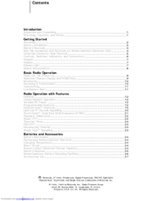
Motorola JT-1000 - SERVICE User Manual (42 pages)
Motorola JT 1000 Portable Radio
Brand:
Motorola
| Category:
Portable Radio
| Size: 0.6 MB
Table of Contents
Table of Contents
1
Getting Started
1
Inspection and Unpacking
1
Introduction
3
Warnings, Cautions, and Notes
3
Getting Started
4
Antennas
4
Battery Installation
5
Battery Removal
5
Belt Clip Installation and Removal (on Nickel-Cadmium Batteries Only)
5
Universal Connector Seal Removal
6
Controls, Switches, Indicators, and Connectors
6
Keypad
7
Display
7
Display Light
7
Status Annunciators
8
Basic Radio Operation
9
Radio On/Off, Power-Up
9
Selective Channel Display and HOME Key
9
Monitoring
10
Receiving a Transmission
10
Transmitting
11
Low-Battery Alert
11
Radio Operation with Features
12
General
12
Coded Squelch Operation
12
Variable RF Power
12
Programmable Features
12
Radio Operation
14
Channel Scan Features
17
Quik-Call II TM Decode Signalling
20
Touch-Code , Dual-Tone Multi-Frequency (DTMF)
21
Repeater Talkaround
22
Smart PTT
22
Time-Out Timer
23
Pac•Rt
23
Receive-Only Channel
23
Single Tone Signalling
23
Batteries and Accessories
24
Battery Information
24
Recharging Nickel-Cadmium Batteries
24
Charging Temperature
24
Short Circuit
24
Memory Effect (Reduced Charge Capacity)
24
Battery Disposal
25
Nickel-Cadmium Battery Recycling Facilities
26
Accessories List
27
General Information
29
Transmitting Distance
29
Radio Care
30
Safety Standards
31
Restrictions
32
Service
33
Express Service Plus (ESP), U.S.A. Only
34
Product Service Information
35
Parts Information
35
Computer Software Copyrights
36
Patent Disclosure
36
Smart Ptt
42
Advertisement
Related Products
Motorola JT 1000
Motorola J2ME
Motorola Jazz
Motorola Jazz Pager
Motorola 68P81083C10-C
Motorola AAH38KDF9DU6
Motorola AAH38RDF9DU6
Motorola AAH38SDF9DU6
Motorola AP 73
Motorola APX Series
MOTOROLA Categories
Cell Phone
Two-Way Radio
Baby Monitor
Cordless Telephone
Radio
More MOTOROLA Manuals
Login
Sign In
OR
Sign in with Facebook
Sign in with Google
Upload manual
Upload from disk
Upload from URL