Sign In
Upload
Manuals
Brands
Mitsubishi Manuals
Inverter
FR-A800
Mitsubishi FR-A800 Manuals
Manuals and User Guides for Mitsubishi FR-A800. We have
3
Mitsubishi FR-A800 manuals available for free PDF download: Instruction Manual, Manual
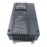
Mitsubishi FR-A800 Instruction Manual (747 pages)
Brand:
Mitsubishi
| Category:
Inverter
| Size: 23.22 MB
Table of Contents
Safety Instructions
2
Contents
4
Table of Contents
7
Abbreviations
12
Introduction
12
Inverter Model
13
Product Checking and Accessories
13
Accessory
14
How to Read the SERIAL Number
14
Component Names
15
Operation Steps
16
Installation and Wiring
18
Peripheral Devices
19
Removal and Reinstallation of the Operation Panel or the Front Covers
23
Inverter and Peripheral Devices
19
Installation of the Inverter and Enclosure Design
27
Removal of the Front Cover (Lower Side)
23
Reinstallation of the Front Covers
24
Removal of the Front Cover (Upper Side)
24
Inverter Installation Environment
27
Standard Environmental Specifications of the Inverter
27
Temperature
27
Humidity
28
Dust, Dirt, Oil Mist
28
Explosive, Flammable Gases
28
Corrosive Gas, Salt Damage
28
Cooling System Types for Inverter Enclosure
29
Vibration, Impact
29
Above the Inverter
30
Installation Orientation of the Inverter
30
Inverter Installation
30
Inverter Placement
30
Arrangement of the Ventilation Fan and Inverter
31
Arrangement of Multiple Inverters
31
Heatsink Protrusion Attachment Procedure
32
Panel Cutting
32
Terminal Connection Diagrams
34
Protrusion of Heatsink of the FR-A840-04320(160K) or Higher
32
When Using a Heatsink Protrusion Attachment (FR-A8CN)
32
Main Circuit Terminals
38
Installation of the Inverter
33
Shift and Removal of a Rear Side Installation Frame
33
FM Type
34
CA Type
36
Details on the Main Circuit Terminals
38
Terminal Layout of the Main Circuit Terminals
39
Wiring of Power Supply and the Motor
39
Handling of the Wiring Cover
41
Control Circuit
46
Applicable Cables and the Wiring Length
42
Total Wiring Length
44
With Induction Motor
44
With PM Motor
44
Earthing (Grounding) Methods and Earthing (Grounding) Work
45
Earthing (Grounding) Precautions
45
Purpose of Earthing (Grounding)
45
Details on the Control Circuit Terminals
46
Input Signal
46
Communication
49
Safety Stop Signal
49
Control Logic (Sink/Source) Change
50
Sink Logic
51
Sink Logic and Source Logic
51
Source Logic
51
When Using an External Power Supply for Transistor Output
51
Wiring of Control Circuit
52
Power Supply Connection
52
Control Circuit Terminal Layout
52
Wiring Method
52
Signal Inputs by Contactless Switches
54
Wiring Precautions
54
Cable Size for the Control Circuit Power Supply
55
Connection Method
55
Starting and Stopping the 24 V External Power Supply Operation
57
When Supplying 24 V External Power to the Control Circuit
57
Specification of the Applicable 24 V External Power Supply
57
Communication Connectors and Terminals
60
Confirming the 24 V External Power Supply Input
57
Function Description
58
Operation While the 24 V External Power Is Supplied
58
Safety Stop Function
58
Connection of Motor with Encoder (Vector Control)
63
Connection Diagram
59
Safety Stop Function Operation
59
Communication Operation
60
PU Connector
60
USB Connector
61
USB Host Communication
61
USB Device Communication
62
RS-485 Terminal Block
62
Appearance and Parts Name of FR-A8AP
63
Terminals of the FR-A8AP
63
Encoder Type Selection Switch (SW3)
64
Motor and Switch Setting
64
Switches of the FR-A8AP
64
Terminating Resistor Selection Switch (SW1)
64
Encoder Cable
65
SF-JR/HR/JRCA/HRCA with Encoder
65
Wiring Example
66
Speed Control
66
Torque Control
66
Connection Terminal Compatibility Table
66
Connection of Stand-Alone Option Units
72
Position Control
67
Vector Control Dedicated Motor (SF-V5RU, SF-THY), 12 V Complementary
67
Instructions for Encoder Cable Wiring
68
Parameter for the Encoder (Pr.359, Pr.369)
69
Parameter Settings for the Motor under Vector Control
69
Combination with the SF-V5RU and SF-THY (ND Rating)
70
Combination with the Vector Control Dedicated Motor
70
Ombination with the SF-V5RU1, 3, 4, and SF-THY (ND Rating)
71
Connection of the Dedicated External Brake Resistor (FR-ABR)
72
Connection Example with the GRZG Type Discharging Resistor
74
Connection of the Brake Unit (FR-BU2)
74
Electro-Magnetic Interference (EMI) and Leakage Currents
83
Connection Example with the FR-BR-(H) Resistor Unit
75
Connection Example with the MT-BR5 Type Resistor Unit
75
Connection of the Brake Unit (BU Type)
76
Connection of the Brake Unit (FR-BU)
76
Connection of the High Power Factor Converter (FR-HC2)
77
Connection of the Power Regeneration Common Converter (FR-CV)
78
Connection of the Power Regeneration Converter
79
Power Supply Harmonics
88
Connection of the DC Reactor (FR-HEL)
80
Precautions for Use of the Inverter
82
Leakage Currents and Countermeasures
83
Line-To-Line Leakage Currents
83
To-Earth (Ground) Leakage Currents
83
Countermeasures against Inverter-Generated EMI
85
Installation of a Reactor
91
Data Line Filter
86
EMI Countermeasure Example
86
Power-OFF and Magnetic Contactor (MC)
92
Outline Dimension Drawings (Zcat3035-1330)
86
How to Enable or Disable the Filter
87
Built-In EMC Filter
87
Countermeasures
88
Countermeasures against Deterioration of the 400 V Class Motor Insulation
93
Checklist before Starting Operation
94
Failsafe System Which Uses the Inverter
96
The Differences between Harmonics and Noises
88
Application of the Specific Consumer Guidelines
89
Operation Panel (FR-DU08)
99
Harmonic Suppression Guidelines in Japan
89
Calculation of Equivalent Capacity P0 of Harmonic Generating Equipment
90
Calculation of Outgoing Harmonic Current
90
Equivalent Capacity Limits
90
Monitoring the Inverter Status
103
Easy Operation Mode Setting (Easy Setting Mode)
104
Harmonic Content
90
Harmonic Suppression Techniques
91
Frequently-Used Parameters (Simple Mode Parameters)
106
Basic Operation Procedure (PU Operation)
108
Determining if a Countermeasure Is Required
91
Handling of the Magnetic Contactor on the Inverter's Output Side
92
Handling of the Manual Contactor on the Inverter's Output Side
92
Inverter Input Side Magnetic Contactor (MC)
92
Basic Operation Procedure (External Operation)
113
Suppressing the Surge Voltage on the Inverter Side
93
Basic Operation Procedure (JOG Operation)
120
Interlock Method Which Uses the Inverter Status Output Signals
96
Backup Method Outside the Inverter
97
Command Speed and Actual Operation Check
97
Start Signal and Actual Operation Check
97
Basic Operation
98
Components of the Operation Panel (FR-DU08)
99
Basic Operation of the Operation Panel
100
Correspondences between Digital and Actual Characters
101
Parameter Setting Mode
101
Changing the Parameter Setting Value
102
Displaying the Set Frequency
103
First Monitored Item
103
Monitoring of Output Current and Output Voltage
103
Simple Mode Parameter List
106
Operating at a Set Frequency
108
Using the Setting Dial Like a Potentiometer to Perform Operation
109
Setting the Frequency by Switches
110
Setting the Frequency with Analog Signals
111
Using an Analog Signal (Current Input) to Give Frequency Command
112
Using the Frequency Set by the Operation Panel
113
Setting the Frequency with Analog Signals (Voltage Input)
116
Changing the Frequency
117
Performing JOG Operation Using External Signals
120
JOG Operation from the Operation Panel
121
Parameters
122
Parameter List
123
Group Parameter Display
149
Changing to the Grouped Parameter Numbers
149
Changing Parameter Settings in the Group Parameter Display
149
Parameter List (by Function Group)
150
Operation Command and Frequency Command
151
Monitor Display and Monitor Output Signal
152
Multi-Function Input Terminal Parameters
152
Motor Constant Parameters
153
Application Parameters
154
Position Control Parameters
156
Operation Via Communication and Its Settings
157
Control Parameter
157
Advanced Magnetic Flux Vector Control
159
Control Method
159
V/F Control
159
Real Sensorless Vector Control
160
Vector Control
160
PM Sensorless Vector Control
161
Vector Control and Real Sensorless Vector Control
162
Block Diagram of Real Sensorless Vector Control
163
Block Diagram of Vector Control
163
Changing the Control Method
165
Selection of Control Method and Control Mode
166
Setting the Motor Capacity and the Number of Motor Poles
166
I/O Signal Operation During the Test Operation
167
PM Sensorless Vector Control Test
167
Selecting the Fast-Response Operation
167
Vector Control Test Operation
167
Valid/Invalid Status of Monitor Outputs During the Test Run
168
Changing the Control Method with External Terminals
169
Changing the Control Mode with External Terminals
170
Selecting the Advanced Magnetic Flux Vector Control
171
Driving Two Motors under Advanced Magnetic Flux Vector Control
172
Keeping the Motor Speed Constant When the Load Fluctuates
172
Selecting the PM Sensorless Vector Control
173
PM Parameter Initialization List
175
Low-Speed Range High-Torque Characteristic Is Set for the Second Motor
177
Low-Speed Range Torque Characteristics
177
When the Low-Speed Range High-Torque Characteristic Is Disabled
177
When the Low-Speed Range Torque Characteristic Is Enabled
177
Control Block Diagram
179
Setting Procedure of Real Sensorless Vector Control (Speed Control)
181
Setting Procedure of Vector Control
183
Setting Procedure of PM Sensorless Vector Control (Speed Control)
184
Setting the Torque Limit Level
186
Block Diagram of Torque Limit
187
Selecting the Torque Limit Input Method
187
Torque Limit Level Using Analog Input
188
Second Torque Limit Level
189
Changing the Setting Increments of the Torque Limit Level
190
Changing the Torque Characteristic of the Constant-Output Range
191
Trip During Torque Limit Operation
191
Adjusting the Stall Prevention Operation Signal and Output Timing
192
Performing High-Accuracy, Fast-Response Control
193
Block Diagram of Easy Gain Tuning Function
194
Execution Procedure for Easy Gain Tuning
194
Parameters Set Automatically by Easy Gain Tuning
195
Adjusting the Speed Control Gain Manually
196
Compensating the Speed Control P Gain in the Constant Output Range
197
When Using a Multi-Pole Motor (8 Poles or More)
197
Setting the Speed Control P Gain in the Per-Unit System
198
Troubleshooting in the Speed Control
199
Speed Feed Forward Control
201
Combining with Easy Gain Tuning
202
Model Adaptive Speed Control
202
Block Diagram
203
Torque Bias
203
Setting the Torque Bias Amount Using Contact Input
204
Setting the Torque Bias Amount Using Terminal 1
204
Setting the Torque Bias Amount Automatically Using Terminal 1
205
Torque Bias Command Via PROFIBUS-DP Communication
205
Torque Bias Operation
206
Speed Limit
207
Speed Deviation Excess Detection
207
Avoiding Motor Overrunning
207
Deceleration Check
208
Notch Filter
209
Pr.1003 Notch Filter Frequency
209
Pr.1004 Notch Filter Depth
209
Pr.1005 Notch Filter Width
209
Torque Control under Real Sensorless Vector Control and Vector Control
210
Operation Transition
212
Operation Example
213
Torque Command by Analog Input (Terminal 1)
217
Torque Command
217
Torque Command by Parameter
218
Modifying the Torque Characteristics in the Constant Output Area
219
Reverse Selection of the Torque Command
219
Torque Command by 16-Bit Digital Input
219
Speed Limit Method Selection
220
Setting Separately for Forward and Reverse Rotation
221
Using the Speed Command During Speed Control
221
Forward/Reverse Rotation Speed Limit Using Analog Input
222
Speed Limit Mode 2
223
Speed Limit Mode 3
224
Speed Limit Mode 4
225
Current Control Integral Time Adjustment
226
Current Loop Proportional (P) Gain Adjustment
226
Speed Limit Mode Switching by External Terminals
226
Troubleshooting in Torque Control
227
Using Two Types of Gain
227
Torque Control by Variable-Current Limiter Control
228
About Position Control
229
Simple Positioning Function by Parameters
233
Positioning by a Point Table
237
Position Data Settings
237
Acceleration/Deceleration Time
238
Auxiliary Function Setting
238
Setting the Waiting (Dwell) Time
238
Return to Home Position During Point Table Positioning
240
Selecting the Home Position Return Method
240
Home Position Return Error
242
Sudden Stop
243
Input/Output Signals for Point Table Positioning
244
Roll Feed Mode
244
Output Signal Operation During Positioning with Home Position Return
245
Position Control by Inverter Pulse Train Input
245
Gain Adjustment of Current Controllers for the D Axis and the Q Axis
256
(E) Environment Setting Parameters
257
Real Time Clock Function
258
Reset Selection/Disconnected PU Detection
260
PU Stop Selection
260
Disconnected PU Detection
261
PU Display Language Selection
262
Buzzer Control
262
PU Contrast Adjustment
262
Reset Limit Function
262
Frequency Change Increment Amount Setting
265
Multiple Rating Setting
266
Changing the Parameter Initial Values and Setting Ranges
266
Using the Power Supply Exceeding 480V
267
Password Function
270
Parameter Reading/Writing Restriction Level
270
Registering a Password
270
Unlocking a Password
271
Parameter Operations During Password Locking/Unlocking
271
Free Parameter
272
Setting Multiple Parameters as a Batch
272
Automatic Parameter Setting
273
PID Monitor Indicator Setting
273
GOT Initial Setting (PU Connector)
274
GOT Initial Setting (RS-485 Terminals)
275
Rated Frequency
275
Extended Parameter Display and User Group Function
276
Display of Simple Mode Parameters and Extended Parameters
276
Registering a Parameter in a User Group
277
Clearing a Parameter from a User Group
277
PWM Carrier Frequency and Soft-PWM Control
278
Changing the PWM Carrier Frequency
278
Soft-PWM Control
278
PWM Carrier Frequency Automatic Reduction Function
279
Inverter Parts Life Display
279
Life Alarm Display and Signal Output
280
Life Display of the Inrush Current Limit Circuit
280
Life Display of the Control Circuit Capacitor
281
Life Display of the Cooling Fan
282
Life Display of Internal Air Circulation Fans
282
Maintenance Timer Alarm
283
Pr.570 Setting
267
Display-Off Mode
263
Resetting USB Host Errors
263
Setting Dial Potentiometer Mode/Key Lock Operation Selection
264
Using the Setting Dial Like a Potentiometer to Set the Frequency
264
Disabling the Setting Dial and Key Operation of the Operation Panel
264
Parameter Write Selection
268
Writing Parameters Only During Stop
268
Disabling Parameter Write
269
Writing Parameters During Operation
269
Current Average Value Monitor Signal
284
Data Output Mask Time Setting
284
Current Average Time Setting
284
Current Average Value Monitor Signal Output Reference Current Setting
285
Maintenance Timer 1 Output
285
Setting the Acceleration and Deceleration Time
286
Clear Signal Selection
246
Operation Outline
246
Selecting the Pulse Train Type
246
Pulse Monitor Selection
247
The Pulse Monitor of the Operation Panel
247
Electronic Gear Setting
248
Gear Ratio Calculation
248
Motor Stop Characteristics
249
Position Command Constant Value During Acceleration/Deceleration
250
In-Position Width
250
Position Adjustment Parameter Settings
250
Excessive Error Level
250
Position Detected Signal
251
Model Adaptive Position Control
252
Position Control Gain Adjustment
252
Position Feed Forward Gain
252
Position Loop Gain
252
Troubleshooting in Position Control
253
Stabilizing Torque Detection
255
Stabilizing Speed Detection
255
Speed Detection Filter and Torque Detection Filter
255
Employing Multiple Primary Delay Filters
255
Excitation Ratio
256
F) Setting of Acceleration/Deceleration Time and Acceleration/Deceleration Pattern
286
Acceleration Time Setting
287
Changing the Minimum Increment of the Acceleration/Deceleration Time
288
Deceleration Time Setting
288
Setting Multiple Acceleration/Deceleration Times
289
Switching Frequency for each Control Method
289
Emergency Stop Function
290
Setting the Acceleration/Deceleration Time in the Low-Speed Range
290
Acceleration/Deceleration Pattern
291
Linear Acceleration/Deceleration
291
S-Pattern Acceleration/Deceleration a
292
S-Pattern Acceleration/Deceleration B
292
Backlash Measures
293
S-Pattern Acceleration/Deceleration C
293
S-Pattern Acceleration/Deceleration D
294
Variable-Torque Acceleration/Deceleration
295
Remote Setting Function
296
Acceleration/Deceleration Operation
297
Clearing the Settings
297
Frequency Setting Storage
297
Output Frequency
297
Start-Time Hold Function
299
Starting Frequency and Start-Time Hold Function
299
Minimum Motor Speed Frequency and Hold Function at the Motor Start up
300
Shortest Acceleration/Deceleration and Optimum Acceleration/Deceleration (Automatic Acceleration/Deceleration)
301
Optimum Acceleration/Deceleration
302
Shortest and Optimum Acceleration/Deceleration Adjustment
303
Lift Operation (Automatic Acceleration/Deceleration)
304
Lift Operation Adjustment
305
D) Operation Command and Frequency Command
306
Operation Mode Selection
306
Operation Mode Selection
307
Operation Mode Switching Method
309
Operation Mode Selection Flow
310
External Operation Mode
311
PU Operation Mode
311
Pu/External Combined Operation Mode 1
312
Pu/External Combined Operation Mode 2
312
Switchover Mode
312
PU Operation Interlock
313
Switching Operation Mode by External Signal
314
Switching the Operation Mode by External Signals
314
Selecting the Operation Mode for Power-ON
316
Startup in Network Operation Mode at Power-ON
316
Start Command Source and Frequency Command Source During Communication Operation
317
Selection of the Command Source of the PU Operation Mode
318
Controllability through Communication
319
Operation at Fault
321
Selection of Control Source in Network Operation Mode
322
Command Source Switchover Via External Terminals
324
Reverse Rotation Prevention Selection
324
Frequency Setting Via Pulse Train Input
325
Selection of Pulse Train Input
325
Adjustment of Pulse Train and Frequency
326
Connection with a Complementary Output System Pulse Generator
326
How to Calculate the Input Pulse Division Scaling Factor
326
Pulse Train Input Specification
326
Speed Synchronized Operation by Pulse Input/Output
327
Speed Synchronized Operation Specification
327
JOG Operation
328
JOG Operation in PU
328
JOG Operation in the External Operation
328
Multi-Speed Setting
329
Operation by Multi-Speed Setting
329
Multi-Speed Setting for 4Th Speed or more
330
(H) Protective Function Parameter
331
Motor Overheat Protection (Electronic Thermal O/L Relay)
332
Electronic Thermal O/L Relay When Using IPM Motor
334
Set Two Types of Electronic Thermal O/L Relays
335
Motor Permissible Load Level Setting
336
External Thermal Relay Input (OH Signal, E.OHT)
337
PTC Thermistor Input
337
Example of PTC Thermistor Characteristics
337
Overheat Protection to Match the Characteristic of the Motor
339
Fault Definition
340
Deceleration Stop at Motor Thermal Protection Activation
340
Output Shutoff at Activation of any Protective Function
340
Cooling Fan Always on
341
Cooling Fan Operation Command Signal
341
Cooling Fan Operation Control
341
Cooling Fan Operation Selection
341
Earth (Ground) Fault Detection at Start
342
Varying the Activation Level of the Undervoltage Protective Function
342
I/O Phase Loss Protection Selection
343
Initiating a Protective Function
343
Retry Count Check
344
Retry Function
344
Setting the Retry Function
344
Selecting Retry Generating Faults
345
Limiting the Output Frequency (Maximum/Minimum Frequency)
346
Setting the Maximum Frequency
346
Setting the Minimum Frequency
346
3-Point Frequency Jump
347
Avoiding the Mechanical Resonance Points (Frequency Jump)
347
6-Point Frequency Jump
348
Stall Prevention Operation
349
Setting Multiple Stall Prevention Operation Levels
353
Stall Prevention Operation Level Setting
354
To Further Prevent a Trip
355
Motor Overspeeding Detection
356
M) Monitor Display and Monitor Output Signal
357
Speed Display and Rotations Per Minute Setting
358
Monitor Display (Setting) Increments
359
Monitor Indicator Selection Using Operation Panel or Via Communication
360
Monitor Description List
361
Monitor Display for Operation Panel
366
Displaying the Set Frequency During Stop
366
Operation Panel Setting Dial Push Display
367
Operation Panel (FR-DU08) I/O Terminal Monitor
367
Cumulative Power Monitor and Clear
368
Cumulative Energization Time and Actual Operation Time Monitor
368
Hiding the Decimal Places for the Monitors
368
Minus Sign Display for the Monitors
369
Monitor Filter
369
Monitor Display Selection for Terminals FM/CA and am
370
Current Monitor Reference
373
Torque Monitor Reference
373
Terminal FM Pulse Train Output
374
High-Speed Pulse Train Output Circuit
374
Monitor Display Selection for Terminals FM/CA and am
376
Calibration Procedure for Terminal FM When Using the Operation Panel
377
Calibration of Terminal am
379
Adjusting the Response of Terminal am
379
Energy Saving Monitor
380
Energy Saving Monitor List
381
Power Saving Real-Time Monitor
382
Average Power Saving Monitor
382
Cumulative Energy Saving Monitors
383
Estimated Power Value in Commercial Power Supply Operation
383
Annual Power Saving Amount and Power Cost Savings
384
Output Terminal Function Selection
385
Output Signal List
385
Adjusting the Output Terminal Response Level
389
Inverter Operation Ready Signals
389
Sensorless Vector Control
390
Forward Rotation and Reverse Rotation Signals
391
Regenerative Status Output Signal
391
Fault Output Signals
392
Input MC Shutoff Signal
392
Output Frequency Detection
393
Low Speed Detection
395
Speed Detection Hysteresis
395
Output Current Detection Function
396
Zero Current Detection
397
Output Torque Detection
398
Remote Output Function
399
Remote Output Data Retention
399
Analog Remote Output Function
401
Analog Remote Output Data Retention
402
Fault Code Output Selection
403
Pulse Train Output of Output Power
404
Detection of Control Circuit Temperature
405
Control Circuit Temperature Monitor
405
Control Circuit Temperature Detection
405
T) Multi-Function Input Terminal Parameters
406
Analog Input Selection
407
Analog Input Specification Selection
407
To Run with an Analog Input Voltage
409
Running with Analog Input Current
410
To Perform Forward/Reverse Rotation with the Analog Input
410
Analog Input Terminal (Terminal 1, 4) Function Assignment
411
Analog Input Compensation
412
Addition Compensation
412
Override Function
413
Analog Input Responsiveness and Noise Elimination
414
Analog Input Time Constant
415
Analog Speed Command Input Time Constant
415
Analog Torque Command Input Time Constant
415
Analog Speed Command Input Offset Adjustment
415
Frequency Setting Voltage (Current) Bias and Gain
416
Analog Input Bias/Gain Calibration
418
Analog Input Display Unit Changing
418
Frequency Setting Voltage (Current) Bias/Gain Adjustment Method
419
Bias and Gain for Torque (Magnetic Flux) and Set Voltage (Current)
422
Calibration of Analog Input Bias and Gain
424
Adjust Method for the Torque Setting Voltage (Current) Bias and Gain
425
Checking of Current Input on Analog Input Terminal
427
Analog Current Input Loss Condition
428
Continue Operation at Analog Current Input Loss
428
Fault Output
429
Fault Output after Deceleration to Stop
429
Function Related to Current Input Check
430
Input Terminal Function Selection
431
Input Terminal Function Assignment
431
Adjusting the Response of Input Terminal
433
Inverter Output Shutoff Signal
434
About Output Shutoff Signal
434
MRS Signal Logic Inversion
434
Selecting Operation Condition of the Second Function Selection Signal (RT) and the Third Function Selection Signal (X9)
435
Start Signal Operation Selection
437
2-Wire Type
437
3-Wire Type
438
Start Signal Selection
438
(C) Motor Constant Parameters
439
Applied Motor
439
Setting the Applied Motor
440
Using Two Types of Motors
441
SF-PR Heavy Duty Setting
442
Offline Auto Tuning
443
Before Performing Offline Auto Tuning
445
Performing Tuning
447
Changing the Motor Constants
449
Offline Auto Tuning for a PM Motor (Motor Constants Tuning)
453
Parameters in Which the Tuning Results Are Set to after Tuning
459
Tuning Adjustment
459
Online Auto Tuning
461
Performing Online Auto Tuning at Startup
461
Online Auto Tuning at Startup Using the External Terminal
462
While the Motor Is Stopped
462
While the X28 Signal Is off
462
While the X28 Signal Is on
462
Signal Loss Detection of Encoder Signals
463
Magnetic Flux Observer
463
Tuning the Second Applied Motor
463
A) Application Parameters
464
Electronic Bypass Function
465
Electronic Bypass Sequence Function
466
Operation of Magnetic Contactor (MC1, MC2, MC3)
467
Electronic Bypass Operation Sequence
468
Operation
469
Example of Operation Sequence with Automatic Bypass Sequence
469
Signal Operation after Setting Parameters
469
Self Power Management
471
Terminal R1, S1 Inputs
471
24 V External Power Supply Input
471
Operation of the Self Power Management Function
472
Brake Sequence Function
474
Setting the Brake Sequence Operation
476
Operation with Brake Opening Completion Signal Input
476
Operation Without Brake Opening Completion Signal Input
477
Set Multiple Brake Sequence Functions
477
Brake Sequence Function When the RT Signal Is on
477
Protective Function
478
Stop-On-Contact Control
479
Connection and Operation Example
479
Setting the Stop-On-Contact Control
480
Function Switching of Stop-On-Contact Control Selection
480
Setting the Frequency During Stop-On-Contact Control
481
Load Torque High Speed Frequency Control
482
Load Torque High Speed Frequency Control Settinge
483
Operation of Load Torque High-Speed Frequency Control
483
Traverse Function
485
Swinging Suppression Control
487
Swinging Suppression Control Operation
487
Swinging Frequency Setting
488
Waiting Time for Brake Operation of Swinging Suppression Control
488
Orientation Control
489
Connection Example
491
Setting I/O Signals
492
Selecting Stop Position Command
492
Pr.361 Position Shift
493
Monitor Display Change
493
Pr.357 Orientation In-Position Zone
493
Relationship between Stop Position Command and 16-Bit Dat
493
Orientation from the Running Status
494
Orientation from the Stop Status
495
Continuous Multi-Point Orientation
496
Servo Torque Selection
497
Description of Orientation Operation
498
Orientation from the Current Rotation Direction
498
Orientation from the Forward Rotation Direction
499
Orientation from the Reverse Rotation Direction
499
Servo Rigidity Adjustment
500
Pr.399 Orientation Deceleration Ratio
500
Pr.351 Orientation Speed (Initial Value: 2 Hz) (Vector Control)
501
PID Control
502
Basic Configuration of PID Control
504
PID Action Outline
504
PID Action
505
Reverse Action
505
Forward Action
505
Relationship between Deviation and Manipulated Amount
505
PID Automatic Switchover Control
509
PID Output Suspension Function
510
Integral Stop Selection at Limited Frequency
511
PID Monitor Function
511
Adjustment Procedure
512
Calibration Example
512
Calibrating Set Point Input
513
Calibrating Measured Value Input
513
Setting Multiple PID Functions
513
Changing the Display Increment of the Numerical Values Used in PID Control
515
Calibration of PID Display Bias and Gain
516
Changing the PID Display Coefficient of the LCD Operation Panel
517
PID Pre-Charge Function
518
Example of Pre-Charge Operation
519
Operation Setting at Pre-Charge Fault
520
Example of Protective Function by Time Limit
520
Example of Protective Function Measured Value Limit
520
Setting Multiple PID Pre-Charge Functions
521
Dancer Control
522
Block Diagram of Dancer Control
523
Outline of Dancer Control
523
Dancer Control Operation Selection
524
Selection of Set Point/Measured Value Input Method
525
Selection of Additive Method for PID Calculation Result
526
Setting the Upper and Lower Limits of the PID Manipulated Amount
526
Input/Output Signals
526
Priority of Main Speed Commands
527
Adjustment Procedure for Dancer Roll Position Detection Signal
528
Automatic Restart after Instantaneous Power Failure/Flying Start with an Induction Motor
529
Automatic Restart after Instantaneous Power Failure Function
530
Connection (CS Signal)
530
Restart Operation with Frequency Search
531
Restart Operation Without Frequency Search
532
Restart Operation with Encoder Detection Frequency Search
532
Restart at Every Start
533
Automatic Restart Operation of MRS (X10) Signal
533
Adjustment of Restart Coasting Time
533
Restart Cushion Time
533
Adjustment of Restart Operation
534
Automatic Restart after Instantaneous Power Failure/Flying Start with an IPM Motor
535
Selection of Restart Operation
536
Restart Coasting Time
536
Offline Auto Tuning for a Frequency Search
537
Offline Auto Tuning When Performing a Frequency Search by V/F Control
538
Before Executing Offline Auto Tuning
538
Power Failure Time Deceleration-To-Stop Function
541
Connection and Parameter Setting
541
Outline of Operation of Deceleration Stop at a Power Failure
542
Action Setting at Undervoltage and Power Failure
542
Power Failure Stop Function
542
Continuous Operation Function at Instantaneous Power Failure
543
Undervoltage Avoidance Function
543
Automatic Adjustment of Deceleration Time
544
Deceleration Stop by the Power Failure Stop External Signal (X48)
544
During Deceleration at Occurrence of Power Failure Signal (Y46)
544
Power Failed Signal (Y67 Signal)
545
PLC Function
546
Copying the PLC Function Project Data to USB Memory
547
Trace Function
548
Selection of Trace Mode
550
Setting of Sampling Cycle (Interval) and Number of Sampling Channels
550
Analog Source (Monitored Item) Selection
551
Trigger Setting
553
Monitoring the Trace Status
555
(N) Operation Via Communication and Its Settings
556
Wiring and Configuration of PU Connector
556
Wiring and Configuration of PU Connector Communication System
557
System Configuration
557
Wiring of Computer by RS-485
557
Wiring and Configuration of RS-485 Terminals
558
RS-485 Terminal Layout
558
Connection of RS-485 Terminals and Wires
558
System Configuration of RS-485 Terminals
559
Computer and Inverter Connection
559
Combination of Computer and Multiple Inverters
559
How to Wire RS-485 Terminals
560
Two-Wire Type Connection
560
Initial Setting of Operation Via Communication
561
Setting the Communication Protocol
561
Communication EEPROM Write Selection
561
Operation Selection at a Communication Error
562
Initial Settings and Specifications of RS-485 Communication
564
Mitsubishi Inverter Protocol (Computer Link Communication)
566
Communication Specifications
566
Communication Operation Presence/Absence and Data Format Types
567
Data Writing Format
567
Data Definitions
569
Control Code
569
Waiting Time
569
Sum Check Code
569
Error Code
570
Response Time
570
Data Check Time
570
Retry Count Setting
571
Signal Loss Detection
572
Instructions for the Program
573
Setting Items and Set Data
575
List of Calibration Parameters
577
Operation Command
578
Inverter Status Monitor
578
Multi Command (HF0)
579
Modbus-RTU Communication Specification
580
Broadcast
581
Error Response
581
Message Format
581
Normal Response
581
Communication Method
582
Message Frame (Protocol)
582
Function Code List
583
Read Holding Register
584
Preset Single Register
585
Diagnostics (Diagnosis of Functions) (H08 or 08)
586
Query Message
586
Preset Multiple Registers
587
Read Holding Register Access Log
588
Modbus Register
590
Operation Mode/Inverter Setting
590
System Environmental Variables
590
Output Signal LF "Alarm Output
593
Pr.343 Communication Error Count
593
USB Communication Specifications
595
USB Device Communication
595
Automatic Connection System Configuration
596
Automatic Connection with GOT
596
GOT2000 Series Automatic Recognition
596
(G) Control Parameters
597
Manual Torque Boost
598
Starting Torque Adjustment
598
Setting Multiple Torque Boosts
598
Base Frequency, Voltage
599
Setting Multiple Base Frequencies
599
Setting of Base Frequency
599
Setting of Base Frequency Voltage
600
Application for Constant-Torque Load
601
Application for Variable-Torque Load
601
Load Pattern Selection
601
Switching Applied Load Selection with a Terminal
602
Vertical Lift Load Applications
602
Energy Saving Control
603
Energy Saving Operation
603
Optimum Excitation Control
603
Adjustable 5 Points V/F
604
SF-PR Slip Amount Adjustment Mode
605
DC Injection Brake, Zero Speed Control, and Servo Lock
606
Setting of Operating Frequency (Pr.10)
607
Setting of Operation Time (X13 Signal, Pr.11)
607
Braking Operation Selection at Time of Real Sensorless Vector Control
608
Setting of Operation Voltage (Torque) (Pr.12)
608
Braking Operation Selection for Vector Control
610
Pre-Excitation Signal (LX Signal)
611
Output Stop Function
612
Make the Motor Perform Coast to Stop
614
Stop Selection
614
Regenerative Brake Selection and DC Feeding Mode
615
Details of the Setting Value
616
When Using Built-In Brake Resistor, Brake Unit
616
When Using High-Duty Brake Resistor
617
When Using Brake Unit
617
When Using Power Regeneration Converter
617
When Using the High Power Factor Converter (FR-HC2)
617
Logic Reversing of Inverter Run Enable Signal
618
Regenerative Brake Usage Rate Alarm Output and Alarm Signal
618
Reset When the Power Is Supplied to the Main Circuit
618
DC Feeding Mode
619
Power Supply Specification for DC Feeding
621
Regeneration Avoidance Function
622
What Is Regeneration Avoidance Operation?
622
To Detect the Regenerative Status During Deceleration Faster
623
Limit Regeneration Avoidance Operation Frequency
623
Adjustment of Regeneration Avoidance Operation
623
Increased Magnetic Excitation Deceleration
625
Setting of Increased Magnetic Excitation Rate
625
Overcurrent Prevention Function
626
Slip Compensation
626
Encoder Feedback Control
627
Setting before Operation
627
Selection of Encoder Feedback Control
628
Feedback Gain
628
Overspeed Detection
628
Droop Control
629
Limiting the Frequency after the Droop Compensation
630
Droop Control Break Point Setting
630
Speed Smoothing Control
631
Advertisement
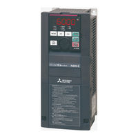
Mitsubishi FR-A800 Instruction Manual (159 pages)
Brand:
Mitsubishi
| Category:
Inverter
| Size: 9.86 MB
Table of Contents
Table of Contents
7
Peripheral Devices
13
Removal and Reinstallation of the Front
16
Installation of the Inverter
19
Terminal Connection
23
Main Circuit Terminals
27
Control Circuit
35
Operation Panel
47
Communication Connectors and Terminals
51
Connection of Motor with Encoder (Vector Control)
55
Parameter Settings for a Motor with Encoder
61
Installing a Communication
74
Electro-Magnetic Interference (EMI) and Leakage Currents
77
Power Supply Harmonics
83
Installation of a Reactor
86
Power-OFF and Magnetic Contactor (MC)
87
Countermeasures against Deterioration of the 400 V Class Motor Insulation
88
Checklist before Starting Operation
89
Failsafe System Which Uses the Inverter
92
Measurement of Powers
126
Measurement of Voltages
126
Measurement of Currents
126
Measurement of Inverter Input Power Factor
126
Measurement of Converter Output Voltage (Across Terminals P and N)
126
Measurement of Inverter Output Frequency
126
Insulation Resistance Test Using Megger
127
Pressure Test
127
Specifications
128
Inverter Rating
129
Common Specifications
130
Inverter Outline Dimension Drawings
132
Appendix
136
Appendix 1 Differences and Compatibility with the FR-A840
137
Appendix 2 Instructions for Compliance with the EU Directives
138
Appendix 3 Instructions for UL and Cul
142
Appendix 4 Instructions for EAC
144
Appendix 5 Restricted Use of Hazardous Substances in Electronic and Electrical Products
145
Appendix 6 Referenced Standard (Requirement of Chinese Standardized Law)
145
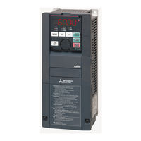
Mitsubishi FR-A800 Manual (83 pages)
Sample Screen
Brand:
Mitsubishi
| Category:
Inverter
| Size: 2.48 MB
Table of Contents
Table of Contents
3
Revisions
5
1 Outline
6
2 System Configuration
6
3 Got
6
System Applications that Are Automatically Selected
6
Controller Settings of Screen Design Software
7
Ethernet Controller Settings of Screen Design Software
7
Overlap Window Settings of Screen Design Software
7
Graphics Mode (Graphics Setting)
7
4 Inverter FR-A800-E
7
Inverter FR-A800-E Communication Settings
7
The Output Terminal Assignment Settings
8
5 Screen Specifications
8
Display Language
8
Screen List/Transition
8
Screen Specifications
11
Menu (B-12000)
11
Startup (B-12010)
12
Operation (B-12020)
13
Maintenance (B-12030)
14
Manual Display (B-12090)
15
Parameter 1 (B-12100)
17
Batch Monitor 1 to 3 (B-12200 to 12202)
18
Operation Command (B-13100)
19
Alarm History (Inverter) (B-14100)
21
Machine Diagnosis (Load Characteristics Measurement) (B-14200)
22
Inverter Life Diagnosis (B-14300)
23
Station Number Switching (W-12010)
24
Parameter Recipe Settings (W-12100)
25
Backup Confirmation Dialog (W-12101)
26
Restoration Confirmation Dialog (W-12102)
27
Machine Diagnosis Confirmation (W-14200)
28
Diagnosis Start Warning (W-14201)
29
Machine Diagnosis Status Dialog (W-14202)
30
Out of Input Range Dialog (W-14900)
31
Alarm Reset (W-30001)
32
Language Setting (W-30002)
33
Clock Setting (W-30003)
34
Device List
35
Comment List
41
Recipe List
43
Script List
60
6 Manual Display
70
Preparing Document Data for Manual Display
70
7 Others
72
Connecting GOT and Inverter Via PLC (Ethernet)
72
Connecting GOT and Inverter Via PLC (CC-Link IE Field Network)
76
Changing the Inverter Channel no
80
Changing the Inverter Network No. and Station no
81
Advertisement
Advertisement
Related Products
Mitsubishi FR-A800-E
Mitsubishi FR-A806-E
Mitsubishi FR-A846-00023
Mitsubishi FR-A846-00126
Mitsubishi FR-A846-00170
Mitsubishi FR-A846-00380
Mitsubishi FR-A846-00470
Mitsubishi FR-A846-00620
Mitsubishi FR-A846-00770
Mitsubishi FR-A846-01160
Mitsubishi Categories
Air Conditioner
Controller
Projector
Automobile
Engine
More Mitsubishi Manuals
Login
Sign In
OR
Sign in with Facebook
Sign in with Google
Upload manual
Upload from disk
Upload from URL