Sign In
Upload
Manuals
Brands
Lincoln Manuals
Automobile
Continental 1964
Lincoln Continental 1964 Manuals
Manuals and User Guides for Lincoln Continental 1964. We have
2
Lincoln Continental 1964 manuals available for free PDF download: Shop Manual, Convertible Top Repair & Adjustment Manual
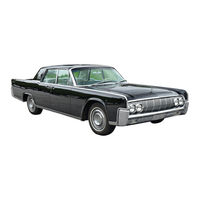
Lincoln Continental 1964 Shop Manual (429 pages)
Brand:
Lincoln
| Category:
Automobile
| Size: 43.84 MB
Table of Contents
Group Index
2
Lincoln-Continental Identification
4
Vehicle Data
4
1964 Lincoln-Continental Warranty Plate
4
Vehide Identification Nvntber Location
4
Trim
5
Date
5
Dso
5
District Code
5
General Brake Service
6
Diagnosis and Testing
6
Preliminary Tests
6
Road Test
6
Booster Inoperative
7
Slow Brake Pedal Return
7
Grabbing Brakes
7
Brake Trouble Symptoms and Possible Causes
8
Common Adjustments and Repairs
9
Parking Brake Linkage Adjustment
9
Master Cylinder Push Rod Adjustment
9
Hydraulic System Bleeding
9
Cleaning and Inspection
10
Brake Assembly
10
Booster Unit
10
Brake System
11
Hydraulic Self-Adjusting Brake System
11
Lincoln Self-Adiusting Bralc:e Assemblies
11
Booster System
12
Booster in Released Position
12
Parking Brake Control Assembly
12
Booster in Applied Position
12
Parking Brakes
13
In-Car Adjustments and Repairs
13
Vacuum Connections for Automatic Parking Brake Release
13
Brake Shoe Adjustments
13
Front Brake Drum
14
Rear Brake Drum
14
Brake Shoes and Adjusting Screw
14
Expanding Brake Shoes
14
Retrading Spring Installation
15
Adiusting Screws and Lever Identification
15
Wheel Cylinder Repair
16
Wheel Cylinder Replacement
16
Brake Backing Plate Replacement
16
Wheel Cylinder
16
Hydraulic Lines
17
Brake Tube Replacement
17
Brake Hose Replacement
17
Service Brake System
17
Vacuum Reservoir
19
Parking Brake Vacuum Power Unit
19
Parking Brake Control and Linkage Connections
19
Brake Pedal
20
Parking Brake System
20
Major Repair Operations
21
Parking Brake Equalizer to Control Assembly Cable
21
Parking Brake Equalizer to Rear Wheel Cable
21
Brake Drum Refinishing
21
Brake Shoe Relining
22
Master Cylinder Disassembly
22
End Plate and Piston Removed
22
Brake Master Cylinder Disassembled
22
Disassembly of Booster Unit
23
Removal of End Plate, Air Cleaner and Booster Piston
23
Removal of Felt Retainer Felt, and Expander Ring
23
Assembly of Booster Unit
23
Assembly of Expander Ring, Felt, and Retainer
24
Assembly of Booster Body, Piston, and End Plate
24
Felt and Expander Ring Installation
24
Specifications
25
Dimensions
25
Brake Check and Adjustments
25
Torque Limits
25
Preliminary Checks
26
Check Fluid Level
26
Check for Fluid Leaks
26
Check Turning Effort
26
Trouble Symptoms and Possible Causes
27
Wheel Alignment Adjustments
28
Caster
28
Camber
28
Toe-In
28
Steering Wheel Spoke Position
29
Turning Angle
29
Wheel Inspection
29
Toe-In and Steering Wheel Spoke Alignment Adiustments
29
Wheel Alignment Definitions
30
Ball Joint Inspection
30
Front Suspension Riding Height Measurement
30
Front Wheel Position for Checking Alignment
30
Riding Height Measurement
31
Power Steering Pump Cleaning and Inspection
31
Front Suspension
31
Rear Suspension Riding Height Measurement
31
Suspension
32
Ball Joint Replacement
32
Rear Suspension Components
33
Front Wheel Spindle
34
Front Shock Absorber
34
Front Spring and Lower Arm
34
Front Suspension Components
35
Coil Spring Compressed for Installation
36
Rear Shock Absorber
36
Upper Arm Shaft Installation Tool
36
Rear Shock Absorber Mounting
37
Lower Mounting Stud Replacement
37
Lower Arm Overhaul-Arm Removed
38
Upper Arm Overhaul-Arm Removed
38
Bushing and Inner Shaft Replacement
38
Rear Spring Overhaul-Spring Removed
39
Front Hanger Assembly
39
Rear Shackle and Hanger Assembly
39
Spring Leaves and Tie-Bolt
39
Steering
40
Power Steering System
40
Torsion Bar Steering Gear
40
Straight-Ahead Position
41
Right Turn
41
Power Steering Gear
41
Valve Detail
41
Steering Wheel Replacement
42
Steering Column Upper Bearing Replacement
42
Power Flows
42
Steering Gear Identification Tag
42
Steering Column and Selector Tube Replacement
43
Steering Column and Selector Lever Tube Details
43
Steering Linkage Replacement
44
Components of Steering Linkage
44
Steering Gear
44
Checking Steering Gear Pre-Load
44
Air Bleeding
45
Pump Reservoir-Withoot Air Conditioning
45
Pre-Load and Mesh Load Adjustments
45
Removing Pitman Arm
45
Pump Reservoir-With Air Conditioning
46
Steering Gear Disassembly
46
Power Steering Pump
46
Removing Cylinder Cap Snap Ring
46
Torsion Bar and Sleeve Disassembly
47
Checking Piston Backlash
47
Removing Sector Shaft
47
Removing Torsion Bar and Sleeve
47
Torsion Bar and Sleeve Assembly
48
Power Steering Gear Disassembled
48
Removing Valve Spool Sleeve
48
Removing Valve Spool Adjuster
48
Assembly of Steering Gear
49
Ball Nut Position
49
Lnstalling Torsion Bar
49
Replacing Sleeve Seal and Bearing
49
Valve Spool Preliminary Centering
50
Pressure Gauge Installed
50
Lnstalling Sedor Shaft
50
Adjusting Centering Spool
51
Power Steering Pump Disassembly
51
Power Steering Pump Assembly
52
Preparation for Installing Rotor Shaft Seals
52
Lnstalling Rotor Shaft in Cover
52
Cam Ring Installation
52
Wheels and Tires
53
Front Wheel Assembly
53
Rear Wheel Assembly
53
Front Hub, Bearings & Grease Retainer
53
Wheel and Tire Assembly
54
Demounting Tire from Wheel
54
Mounting Tire to Wheel
54
Tire Rotation
54
Removing Grease Retainer
55
Front Wheel Bearing Cup Installation-Front Wheel Bearing Cup Removal
55
Grease Retainer Installation
55
Front Hub and Drum Assembly Replacement
56
Front Wheel Alignment
57
Front Suspension Torque Limits
57
Steering Checks and Adjustments
57
Steering Torque Limits
57
General Axle Service
58
Rear Axle Trouble Diagnosis Guide
58
Excessive Rear Axle Noise
58
Pinion and Ring Gear Tooth Contact Adjustment
59
Pinion Location
59
Backlash between Ring Gear and Pinion
59
Pinion Bearing Preload
60
Pinion and Ring Gear Tooth Contact Adjustments
60
Tooth Contact Pattern Check
60
Inspection before Disassembly of Carrier
61
Determining the Shim Packs
61
Axle Housing Assembly in Holding Fixture
61
Backlash Check
61
Gears
62
Bearing Cups and Cone and Roller Assemblies
62
U-Joint Flange
62
Carrier Housing
62
Rear Axle
63
Conventional Axle
63
Rear Axle Assembly
63
"Directed Power" Axle
64
Rear Axle Shaft, Wheel Bearing, and Oil Seal Replacement
65
Drive Pinion Oil Seal Replacement
65
Axle Shaft Removal
65
Rear Wheel Bearing Removal
65
Pinion Shaft Nut Removal or Installation-Axle in Cor
66
Pinion Shaft Oil Seal Removal
66
U-Joint Flange Installation on Car
66
U-Joint Flange Removal-Axle in Car
66
Rear Axle Housing Assembly
67
Rear Wheel Bearing Oil Seal Removal
67
Rear Wheel Bearing Oil Seal Installation
67
Spreading Carrier Housing
68
Differential Bearing Cap Locating Marks
68
Pinion Shaft Nut Removal
68
Pinion and Bearing Assembly Removal
68
Conventional Differential Case Disassembly
69
"Directed Power" Differential Case Disassembly
69
Pinion Rear Bearing CUP Removal
69
Pinion Front Bearing Removal
69
Drive Pinion and Ring Gear Set
70
Pinion and Ring Gear Markings
70
Pinion Rear Bearing Installation
70
Differential Case, Bearings, and Ring Gear
71
Conventional Differential Case Assembly
71
Positioning of Parts for Assembly
71
Installation of Side Gear Ring, Discs, and Plates in Case
71
Installation of Pinion, Bearings, and Differential Case
72
Measuring Differential Case Side Clearance
72
Pinion Rear Bearing Cup Installation
72
Pinion Front Bearing Cup Installation
72
Measuring Pinion Bearing Preload
73
Measuring Pinion Depth
73
Pinion Depth Gauge Adjustment
73
Calibration Chart (Gauge 4020-B)
74
Establishing Pinion Bearing Preload
74
U-Joint Flange Deflector Installation
74
U-Joint Flange Installation-On Bench
74
Differential Bearing Preload and Ring Gear Backlash Adjustment
75
Pinion and Drive Gear Identification
76
Pinion Bearing Preload Adjustment
76
Drive Pinion Adjusting Shim Thickness Changes
76
Drive Line
78
Lubrication Tool
78
Drive Shaft Disassembled
78
Drive Line Balance
79
Drive Line Angle Check
79
Cheddng Pinion Nose Angle-Typical
79
Removing Bearing Cup from Centering Socket Yoke
80
Removing Bearing Cup from Center Yoke
80
Removing Center Socket Yoke
80
Partially Removing Bearing Cup from Center Yoke
80
General Transmission Service
82
Transmission Fluid Level Check
82
Transmission Fluid Leakage Checks
82
Converter Area Oil Leakage
82
Converter Leakage Check
83
Converter Area Oil Leakage Checks
83
Engine Idle Speed Check
84
Manual Linkage Checks
84
Transmission Vent at Front of Transmission Case
84
Converter Leak Checking Tool
84
Control Pressure Is Low
85
Control Pressure Is High
85
Control Pressure Does Not Rise with Throttle Opening
85
Control Pressure Is Extremely Erratic
85
Initial Engagement Checks
86
Shift Point Checks
86
Transmission Case Hydraulic Passages
86
Converter Check
87
Air Pressure Checks
87
Front Clutch
87
Governor
87
Diagnosis Guide
88
Converter Cleaning
89
Oil Cooler Flushing Procedure
89
Turbine and Stator End Play Check
89
Stator One-Way Clutch Check
90
Stator to Impeller Interference Check
90
Stator to Turbine Interference Check
90
Typical Converter Checking Tool
90
Output Shaft and Primary Sun Gear Shaft
91
Distributor Sleeve
91
Pinion Carrier, One-Way Clutch and Center Support
91
Extension Housing
91
Front Pump
92
Rear Pump
92
Pressure Regulator
92
Valve Body
92
Front Servo
93
Rear Servo
93
Case
93
Turbo-Drive Automatic Transmission
94
Turbo-Drive Transmission
94
To Start the Engine
94
To Engage the Transmission
95
Torque Converter Operation
95
Transmission Identification Tag
95
Planetary Gear Train
96
Rear Clutch
96
Front Band and Servo
96
Rear Band and Servo
96
Typital Power Flow-Eath Gear Ratio
97
Power Flows-Each Gear Ratio
98
Power Flow- Neutral
98
Power Flow - First Gear, L
98
Power Flow-First Gear, D1
98
Vacuum Controlled-Main Control, Hydraulic Circuit
99
Governor Pressure
100
Transition Valve
100
1-2 Shift Valve
100
Throttle Reducing Valve
100
Hydraulic Control System-Neutral
101
Hydraulic Control System- D1, First Gear
101
Hydraulic Control System - D1, Second Gear
101
Linkage Adjustments
102
Accelerator Pedal Height Check
103
Downshift Rod
103
Typical Unkage Adiustments
103
Starter Neutral Switch Location
103
Manual Linkage
104
Starter Neutral Switch Adjustment
104
External Transmission Components
104
Front Band Adjustment
105
Rear Band Adjustment
105
Governor Replacement
105
Oil Pan And/Or Control Valve Body Replacement
106
Hydraulic Pressure Tubes
106
Pressure Regulator Replacement
107
Parking Pawl Replacement
107
Vacuum Unit Removal or Installation
107
Extension Housing Seal & Bushing Removal
107
Extension Housing Oil Seal and Bushing Replacement
108
Internal Bolt- Retaining Converter Housing to Case
108
Oil Coolant Line Routing
108
Converter and Converter Housing
109
Transmission Sub-Assemblies
109
Output Shaft Thrust Washer
110
Gear Train Positioned in Holding Fixture
110
Removing Transmission Gear Train
110
Removing Rear Clutch from Primary Sun Gear Shaft
110
Clutch and Gear Train-Explode
111
Removing Belleville Spring Snap Ring
112
Rear Servo Assembly
112
Removing Rear Servo Snap Ring
112
Removing Spring Retainer Snap Ring from Rear Clutch
112
Parts Repair and Replacement
113
Removing Front Servo Snap Ring
113
Front Pump Disassembled
113
Control Valve Body
114
Main Control Valve Body-Exploded View
115
Manual and Parking Pawl Linkage
116
Removing Parking Pawl Toggle Pin
117
Installing Front Servo Piston
117
Installing Front Servo Cover
117
One-Way Clutch Installation on Center Support
117
Installing Rear Servo Apply and Release Tube
118
Installing Compensator Tube
118
Installing Main Pressure Tube
118
Installing Rear Pump Pressure Tube
118
Control Pressure Ranges
120
Transmission Gear Ratios
120
Stall Speeds
120
Lubricant Refill Capacity
120
General Engine Service
122
Engine will Not Crank
122
Engine Cranks Normally, but will Not Start
122
Engine Starts, but Fails to Keep Running
123
Engine Runs, but Misses
124
Camshaft Lobe Lift
128
Manifold Vacuum Test
128
Compression Test
129
Hydraulic Valve Lifter Tests
129
Manifold Vacuum Gauge Readings
129
Valve Clearance
130
Positive Crankcase Ventilation System Test
130
Placing Steel Ball in Valve Lifter Plunger
130
Adjusting the Ram Length
130
Valve Rocker Arm Shaft Assembly
131
Push Rods
131
Cylinder Heads
131
Reaming Valve Guides
131
Valves
132
Refacing Valves
132
Select Fitting Valves
132
Camshaft
132
Fitting Piston Pins
133
Refinishing Cylinder Walls
133
Intake Manifold
134
Exhaust Manifolds
134
Hydraulic Valve Lifters
135
Timing Chain and Sprockets
135
Valve Stem Clearance
135
Checking Valve Spring Tens Ion
135
Connecting Rods
136
Pistons, Pins and Rings
136
Crankshaft Journal Measurements
136
Typical Bearing Failures
136
Main and Connecting Rod Bearings
137
Cylinder Block
137
Oil Pan
137
Oil Pump
137
Crankcase Ventilation System Maintenance
138
430 V-8 Engine
139
Table of Contents
139
Valve Train
140
Front Sectional View
140
Intake Manifold and Cylinder Head Valve Ports
140
Typical Hydraulic Valve Lifter Operation
141
Lubrication System
141
Positive Crankcase Ventilation System
142
Cooling System Stages
143
Engine Supports
144
Engine Front Support
144
Engine Lateral Restrictor
145
Engine Rear Support
145
Intake Manifold Bolt Torque Sequence
146
Valve Push Rod Chamber Cover
147
Valve Rocker Arms, Shafts and Push Rods
147
Repairs
148
Valve Mechanism and Related Parts
148
Rocker Arms and Shaft Installed- Left Bank
148
Hydraulic Valve Lifters
148
Hydraulic Valve Lifter Assembly
149
Lock Ring Installation
149
Lifter Removal or Installation
149
Lifter Plunger Removal
149
Positive Crankcase Ventilation System
149
Cylinder Head Holding Fixtures
150
Cylinder Head Bolt Torque Sequence
150
Cylinder Head and Related Parts
151
Compressing Valve Spring-On Bench
152
Measuring Intake Valve Spring Assembled Height
152
Valve Spring Spacer Installation
152
Compressing Valve Spring-In-Chassis
152
Valve Spring, Retainer and Stem Seal
152
Replacement
152
Crankshaft Damper
153
Cylinder Front Cover
154
Timing Chain, Camshaft and Crankshaft Sprockets
155
Alignment of Timing Marks
155
Crankshaft Sprocket Removal
155
Camshaft and Related Parts
156
Camshaft Rear Bearing Bore Plug Replacement
157
Main and Connecting Rod Bearing Replacement
157
Checking Bearing Clearance
158
Seal to Rear Bearing Cap Installation
158
Cutting Rear Bearing Cap Seal
158
Connecting Rod Bearing Replacement
159
Piston and Connecting Rod Assembly
159
Conneding Rod Side Clearance
159
Removing Cylinder Ridge
160
Piston Installation
160
Piston Pin Removal- Arbor Press
160
Piston Pin Removal- Manual
160
Piston, Connecting Rod and Related Parts
161
Connecting Rod and Piston Assembly
161
Piston Pin Installation-Arbor Press
161
Oil Filter and Adapter
162
Flywheel
162
Oil Pan
162
Oil Pump
163
Oil Filler Pipe and Cap
164
Crankshaft and Related Parts
167
Major Repair Operations
167
Cutting Rear Main Bearing Seal in Cylinder Block
168
Lnstalling Rear Main Bearing Seal in Cylinder Block
168
Camshaft Bearing Replacement
169
Thrust Bearing Alignment
169
Crankshaft End Play
169
Camshoft Bearing Removal and Installation
169
Engine Disassembly
170
Camshaft Front Bearing Measurement
170
Cylinder Block Plugs and Fitings
171
Engine Assembly
171
General Ignition System Service
178
Conventional Ignition System
178
Typical Ignition Circuit
178
Trouble Isolation
179
Transistor Ignition System Schematic
179
Amplifier Assembly
179
Primary Circuit Tests
180
Transistor Ignition System
180
Battery to Coil Test-Sun Tester
180
Ignition Switch Test
180
Secondary Circuit Tests
183
Ignition Timing
184
Ignition System Tests-Rotunda Testers
184
Rotundo RE-235 Test Connedions
184
Rotunda RE-651 Test Connections
185
Rotunda RE-881 Test Connedions
186
Superimposed Secondary Pattern
187
15 Kv Pattern
187
Normal Superimposed Secondary Pattern
187
30 Kv Pattern
188
Sun 900 Tester Connections
188
Ignition System Tests-Sun 900 Tester
188
Cranking Voltage
189
Breaker Points
189
Coil
189
Typical Scope Pattern
189
Primary Resistance
190
Secondary Resistance
190
Available Voltage
190
Secondary Insulation
190
Distributor Diaphragm Leakage and Freeness of Operation
191
Distributor Shaft End Play
191
Breaker Point Resistance
191
Insulation and Leakage
192
Mechanical Operation
192
Dwell Angle
192
Distributor Spark Advance
192
Condenser Testing
193
Distributor Resistance
194
Cam Lobe Accuracy
194
Vacuum Advance
194
Adiusting New Breaker Point Gop
195
Aiigning Breaker Points
195
Adiusting Spring Tens Ion
195
Adjusting Spring Tension
196
Timing Mark Locations
196
Spark Plug Wire Replacement
196
Gapping Spark Plugs
196
Cleaning Plug Electrode
197
Spark Plug Inspection
197
Spark Plugs
198
Distributors
198
Dual Advance Distributors
199
Typical Dual Advance Distributor
199
Diaphragm and Breaker Plate Assembly
200
General Fuel System Service
206
Fuel Tank, Lines and Filter
206
Vapor Discharge Valve and Fuel Pump
206
Vapor Discharge Valve
206
Fuel Pump, Tank and Lines Diagnosis Guide
207
Fuel Pump Pressure and Capacity Tests
207
Air Duct
208
Carburetor
208
Idle Speed-Up Control
208
Accelerating Pump Discharge
208
Carburetor Bench Adjustments
210
Float Adjustments
210
Accelerator Pump Adjustments
210
Float Drop
210
Choke and Countershaft Linkage Adjustment
211
Automatic Choke Adjustment
211
Fast Idle Linkage Adjustment
211
Choke Piston Lever Adiustment
211
Unloader Adjustment
212
Anti-Stall Dashpot Adjustment
212
Secondary Throttle Lever Adjustment - Bench Only
212
Fast Idle Speed Bench Adiustment
212
Secondary Throttle Lockout Adjustment
213
Throttle Linkage Adjustments - on the Car
213
Fuel Filter Replacement
213
Anti-Stall Dashpot Adiustment
213
Primary and Secondary Closing Shoe Clearance
214
Secondary Throttle Lever Adjustment
214
Fuel Pump
215
Air Cleaner Maintenance
215
Body and Cover
215
Carter Carburetor
216
Fuel Inlet System
216
Thermostatic Choke
217
3-Carter 4-Barrel Carburetor-Bottom View
217
Unloader
218
Low Speed (Idle) Fuel System
218
Thermostatic Choke Unit and Linkage
218
Choke System
219
Low Speed System
219
Idle Speed-Up Control-With Air Conditioning
220
Accelerating Pump System
220
Low Speed Idle Mixture System
220
Idle Speed-Up System
220
High Speed System
221
Auelerating Pump System
221
Primory High Speed System
221
Secondory High Speed System
222
Anti-Stoll Doshpot
222
Idle Fuel Mixture and Idle Speed Adjustments
223
Anti-Stall Dashpot
223
Initial Idle Speed and Mixture Settings
223
Hot Idle Rpm Adjustment
223
Main Body
226
Throttle Plate Removal
226
Choke Plate and Shaft Installation
226
Fuellnlet Needle, Seats, and Float Installed
226
Positioning Primary Throttle Plates
227
Secondary Throttle Return Spring Installed
227
Secondary Over-Ride Spring Installed
228
Vacumeter (Metering Rod) Installation
228
Bench Adjustments
229
Dashpot Arms Installation
229
Countershaft Lever Installation
229
Air Cleaner and Air Duct
230
Air Inlet Duct and Air Cleaner-Sectional View
230
Air Inlet Duct Installed
230
Fuel Pump and Vapor Discharge Valve
232
Fuel Pump and Vapor Discharge Valve-Sectional View
233
Fuel Pump, Vapor Return Valve, and Filter
234
Scribe Marked Fuel Pump
235
Rocker Arm Pin Seal Plug Removal
235
Rocker Arm Pin Removal or Installation
235
Fuel Pump Diaphragm Removal or Installation
235
Fuel Tank and Lines
236
Filler Pipe
236
Fuel System Installation
237
Fuel Tank Filler Pipe Puller-Fabricated
238
Fuel Lines
238
Fuel System Specifications
239
General Cooling System Service
240
Cooling System Pressure Test
241
Thermostat Tests
241
Power Booster Clutch
241
Draining and Filling the Cooling System
241
Drive Belts
242
Fan Replacement
242
Fan Belt Replacement
242
Radiator Hose Replacement
242
Cooling System Flushing Procedures
243
Reverse Flushing Procedure
243
Power Flushing Procedure
243
Radiator Flushing Procedure
243
Water Pump
244
Water Pump and Pulley
245
Water Pump Pulley Removal
245
Shaft and Bearing, Seal and Impeller Removal
245
Lnstalling Water Pump Shaft and Bearing
245
Radiator, Supply Tank and Thermostats
246
Thermostat Locations
246
Radiator
247
Radiator Supply Tank and Thermostat
247
Cylinder Block Thermostats
247
Fan Drive Clutch
248
Exhaust System
250
Exhaust System Alignment
250
Lincoln Continental Exhaust System
251
Resonator Inlet Pipe
252
Resonator
252
Exhaust Muffler
252
Lincoln Continental Exhaust System Clearance Dimensions
253
General Charging System Service
256
Test Cir(Uit Resistance
257
Resistance Excessive
257
Resistance Normal
257
Test Alternator Regulator
257
Aiternator Electrical Connections
258
Aiternator Output Test
258
Field Open or Short Circuit Test
258
Positive Diode Test
259
Negative Diode Test
259
Field Relay Test
259
Voltage Limiter Test
259
Regulator and Circuit Tests
260
General Starting System Service
270
Starter Load Test
272
Starter No-Load Test
272
General Lighting System, Horns, and Instruments Service
278
Light Trouble Diagnosis Guide
278
Instrument Trouble Diagnosis Guide
278
Horn Trouble Diagnosis Guide
279
Turn Indicator Trouble Diagnosis Guide
279
Windshield Wiper Trouble Diagnosis Guide
280
Horn Test
280
Headlight and Beam Selector Switch Tests
280
Constant Voltage Regulator Test
280
Fuel Gauge and Fuel Level Sending Unit Test
281
Low Fuel Level Warning System Test
281
Temperature Gauge Test
281
Temperature Sending Unit Test
281
Lighting System and Horns
282
Headlights
282
Headlight Alignment
282
Horns
282
Exterior Lighting, Turn Signals, Horns and Backup Lights
283
Parking Light
284
Tail and Stop Light
284
Back-Up Lights
284
License Plate Light
284
Instrument Panel Lights and Wiring
285
Instrument Lights
286
Ash Tray Lights
286
Glove Compartment Light
286
Map Light
286
Switches, Circuit Breakers and Fuses
287
Headlight Switch
287
Headlight Beam Selector Switch
287
Stop Light Switch
287
Map Light Switch or Antenna Switch
288
Glove Compartment Light Switch
288
Instruments
289
Gauges
289
Fuel Gauge
289
Low Fuel Level Warning System
289
Lnterior Lighting, Gauges, and Heater Schematic
290
Windshield Wiper Blade Adjustment
291
Lower Instrument Panel
291
Clock
291
Windshield Wiper
291
Constant Voltage Regulator
292
Fuel Sending Unit
292
Temperature Gauge
292
Oil Pressure Gauge
292
Charge Indicator Gauge
293
Turn Indicator
293
Turn Indicator Flasher
293
Speedometer
293
Wiper Motor
294
Wiper Control
294
Wiper Pivot Shaft and Link
294
Left Pivot Shaft and Link
294
Bulb Chart
295
Circuit Protection
295
General Ventilating, Heating, and Accessories Service
296
Ventilating and Heating Trouble Diagnosis Guide
296
Air Conditioning Trouble Diagnosis Guide
296
Radio Trouble Diagnosis Guide
297
Electric Antenna Trouble Diagnosis Guide
297
Speed Control Trouble Diagnosis Guide
297
Wiring Diagram
298
Automatic Headlight Dimmer
299
Testing Ventilating and Heating
299
Driver Control Knob
299
Heater Vacuum Line Operation (Regulator Lever at MAX)
299
Air Conditioning
300
Vacuum Drop Vs. Vents-Heater Lever Position
300
Heater-Vacuum Line Connedions
300
Heater-Air Conditioner-Vacuum Line Connections
301
Checking for Leaks
302
Speed Control
302
Manifold Gauge Set
302
Testing for Leaks
303
Trouble Shooting-Locked on Low Beam
303
Trouble Shooting-Lotked on Upper Beam or no Over-Ride
304
Compressor Oil Level Check
305
Checking System Pressures
305
Compressor Oil Level Dip Stick
305
Ventilating and Heating
306
Heater Core and Water Temperature Control
306
Vacuum Actuators
306
Bracket Adjustment
306
Regulator Valve
307
Blower Motor
307
Blower Switch
307
Heater Blower Wiring Circuit
307
Receiver Unit
308
Evaporator Unit
308
Expansion Valve
308
Expansion Valve and Liquid Sight Glass
308
Liquid Sight Glass
309
Magnetic Clutch
309
Compressor Unit
309
Service Valves
309
Isolating the Compressor
310
Charging the System
310
Evacuating the System
310
Making a Partial Charge
310
Making a Complete Charge
311
Charging from Small Containers
311
Charging the Air Conditioning System
311
Evaporator
312
Evaporator Core
313
Evaporator Shutter Actuator
313
Compressor
313
York Compressor Assembly
313
Compressor Components
314
Valve Plate
314
Wiring Diagram Heater and Air Conditioner
314
Clutch
315
Crankshaft Seal
315
Heater Core, Regulator Valve, and Vents-Heater Valve
315
Radio
316
Push Button Adjustment
316
Antenna Installation
316
Antenna
319
Front Speaker
319
Rear Seat Speaker
319
Speed Control Unit-Cover Removed
320
Control Cable
321
Brake Pedal Release Switch
321
Control Unit
321
Selector Assembly and Cable Removal
321
Automatic Head Light Dimmer Installation
322
Phototube Unit
322
Amplifier Unit
322
Foot Control Switch
322
Phototube Unit Vertical Aiming Procedure
323
Hold and DIM Sensitivity Adjustments on Car
323
Hold Sensitivity Adjustment
323
DIM Sensitivity Adjustment
324
Amplifier Unit and Harness
324
Foot Dimmer Switch
324
Blower Motor Current Draw
325
Air Conditioning Compressor
325
Driven Belt Tension
325
General Body Service
326
Types of Sealer and Application
326
Body Maintenance
326
Sealer Application-Front Floor Pan, Cowl Side and Dash Panel
327
Body Alignment
328
Checking Body for Misalignment
328
Sealer Application-Roof and Upper
328
Sealer Application-Side and Center Floor Pan
329
Sealer Application-Rear Floor Pan and Body Rear
330
Checking Underbody for Misalignment
331
Paint Damage and Repair
331
Paint Repairs on Galvanized Metals
331
Paint Refinishing
331
Paint Defects and Repair Procedures
332
Random Blisters Pattern Blisters
332
Line Checking
332
Crow Footing
332
Interior Paint Repairs
334
Rattle Elimination
334
Scuff Plates and Pads-Installation
334
Floor Pan Plugs and Grommets
335
Drain Valves
335
Dust and Water Leaks
335
Exterior Cleaning
335
Rail Type (Free Wheeling) and Fork Lift (Twin Post) Hoists
336
Frame Contact Hoist
336
Jacking Instructions
336
Floor Jack
336
Front Sheet Metal, Bumpers, and Exterior Mouldings
337
Hood
337
Front Bumper Bar Extension
337
Front Impact Bar
337
Front Bumper Installation
338
Radiator Grille Installation
338
Cowl Top Ventilation Grille and Screen
339
Radiator Grille
339
Rear Bumper
339
Rear Bumper Installation
339
Exterior Moulding Installation
340
Exterior Mouldings
341
Doors, Windows and Deck Lid
342
Vacuum Door Lock
342
Vacuum-Operated Door Locking System
342
Complete System Inoperative
342
Power Windows
343
Power Window Circuit
344
Automatic Rear Door Window Circuit
346
Vacuum Luggage Compartment Lock
347
Automatic Rear Door Windows (Model 74A) Operation
348
Window-Down Circuit
348
Window-Up Circuit
348
Vacuum Controlled Luggage Compartment Door Lock
349
Window Bypass Switch
349
Front Door and Vent
349
Rear Door Window
350
Front Door Window Adjustment
350
Front Door Window Mechanism
351
Windshield
352
Front and Rear Door Hinges
352
Door Lock Striker Adjustment
352
Rear Door Window Adiustment
352
Inside Rear View Mirror
354
Front Door Hinge Adjustments
354
Rear Door Hinge Adjustments
354
Lock Striker Adjustment
354
Windshield and Exterior Mouldings
355
Front Door Lock
356
Windshield Prepared for Installation
356
Bonded Windshield Rear View Mirror Installation
356
Vent Window Motor
357
Front Door Window
357
Window Regulator Motor
357
Vent Window Frame
358
Front Door Window Regulator
358
Rear Door Outside Handle
358
Rear Door Lock
358
Remote Control
359
Rear Door Hinges-Upper and Lower
359
Back Window And/Or Weatherstrip
359
Luggage Compartment
360
Lock Cylinder
360
Luggage Compartment Lock Mechanism
360
Interior Trim
362
Door Trim Panel
362
Door Water Shields
362
Headlining
364
Instrument Panel Pad
364
Headlining Installation
364
Advertisement
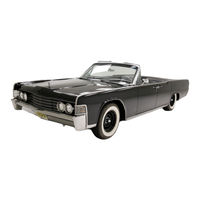
Lincoln Continental 1964 Convertible Top Repair & Adjustment Manual (22 pages)
Brand:
Lincoln
| Category:
Automobile
| Size: 2.28 MB
Table of Contents
Table of Contents
3
Description and Operation
4
Electrical System
5
Hydraulic System
6
Deck Open Cycle
6
Top up Cycle
6
Deck Close Cycle
8
Top down Cycle
8
Schematic Diagrams
10
Top Retract Cycle
10
Deck Lid Unlock IQ
10
Deck Lid Open
11
Upper Bock Panel Erect
12
Top Unlock
13
Top Retract I4
14
Deck Lid Close and Lock
15
Deck Lid Unlock
16
Deck Lid Open
17
Top Erect
18
Top Lock
19
Upper Back Panel Retract
20
Deck Lid Close and Lock
21
Advertisement
Related Products
Lincoln Continental 2001
Lincoln Continental 1965
Lincoln CORSAIR 2023
Lincoln Town Car 2007
Lincoln Town Car 1998
Lincoln Town Car 2000
Lincoln Town Car 2004
Lincoln Town Car 2011
Lincoln Town Car 2010
Lincoln TOWN CAR 1999
Lincoln Categories
Automobile
Water Pump
Welding System
Oven
Tools
More Lincoln Manuals
Login
Sign In
OR
Sign in with Facebook
Sign in with Google
Upload manual
Upload from disk
Upload from URL