Sign In
Upload
Manuals
Brands
Honeywell Manuals
Security System
Gamewell-FCI ILI-MB-E3
Honeywell Gamewell-FCI ILI-MB-E3 Manuals
Manuals and User Guides for Honeywell Gamewell-FCI ILI-MB-E3. We have
1
Honeywell Gamewell-FCI ILI-MB-E3 manual available for free PDF download: Installation & Operation Manual
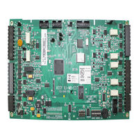
Honeywell Gamewell-FCI ILI-MB-E3 Installation & Operation Manual (190 pages)
Expandable Emergency Evacuation System
Brand:
Honeywell
| Category:
Security System
| Size: 15.58 MB
Table of Contents
Fcc Warning
4
Installation Precautions
4
Table of Contents
6
Section 1: System Overview
11
Description
11
Standard Features
11
1: Optional Features
12
System Components
12
1: Control and Indicator Sub-Assembly (LCD-E3)
12
2: Intelligent Loop Interface - Main Board (ILI-MB-E3)
13
3: Intelligent Loop Interface XP95 - Main Board (ILI95-MB-E3)
13
4: Addressable Node Expander (ANX)
13
5: Power Supply - 9 Amperes (PM-9/PM-9G)
13
Optional Modules
14
1: Addressable Switch Sub-Assembly (ASM-16)
14
2: Digital Alarm Communicator Transmitter (DACT-E3)
14
3: Repeater (RPT-E3)
14
4: Intelligent Loop Interface - Slave Board (ILI-S-E3)
14
5: Intelligent Loop Interface XP95 - Slave Board (ILI95-S-E3)
14
6: Addressable Node Expander (ANX)
15
7: Remote LED Driver (ANU-48)
15
8: LCD Network Graphic Annunciator (NGA)
15
9: Remote LCD Display (LCD-7100)
15
10: Intelligent Network Interface - Voice Gateway (INI-VG Series)
15
11: AM-50 Series, 50 Watt Amplifiers
16
Specifications
17
1: Power Supply (PM-9/PM-9G)
17
2: Signaling Line Circuits (ILI-E3 or ILI95-E3 Series)
17
3: Notification Appliance Circuits (ILI-MB-E3 or ILI95-MB-E3)
18
4: Alarm Dry Contacts (ILI-MB-E3 or ILI95-MB-E3)
18
5: Trouble Dry Contacts (ILI-MB-E3 or ILI95-MB-E3)
18
6: Supervisory Dry Contacts (ILI-MB-E3 or ILI95-MB-E3)
18
7: Earth Ground Connection (ILI-MB-E3 or ILI95-MB-E3)
18
8: 24 VDC Power, System (ILI-MB-E3 or ILI95-MB-E3)
18
9: RS-232 Port
18
10: Battery Connection (PM-9/PM-9G)
19
11: City Master Box Output (ILI-MB-E3 or ILI95-MB-E3)
19
12: Remote Signaling Output (Polarity Reversal)
19
13: Releasing Service (ILI-MB-E3 or ILI95-MB-E3)
19
Section 2: Installation
20
General
20
Installation Requirements
20
Unpacking and Inspecting Components
20
Mounting Sub-Assemblies
20
Cabinets
21
1: Cabinet A1, Installation Instructions
21
Cabinet A1, Backbox Installation
22
Cabinet A1, Trim Rings Installation (Optional Accessory)
23
Cabinet A1, Outer Door Installation
24
Cabinet A1, Inner Door to the Backbox Installation
25
Cabinet A1, Inner Door Installation
26
2: Cabinet A2, Installation Instructions
27
Cabinet A2, Backbox Installation
28
Cabinet A2, Trim Rings Installation (Optional Accessory)
29
Cabinet A2, Outer Door Installation
30
Cabinet A2, Inner Door to the Backbox Installation
31
Cabinet A2, Inner Door Installation
32
3: E3-BBFLUSH-LCD, CAB A2 Flush Annunciator Installation Instructions
33
E3BB-FLUSH-LCD, CAB A2, Remote Flush Annunciator Backbox Installation
34
E3BB-FLUSH-LCD, CAB A2, Remote Flush Annunciator to the Backbox Installation
35
4: Cabinet a or AA, 2-Bay Installation Instructions
36
Cabinet a or AA, 2-Bay and 3-Bay Backbox Installation
37
Cabinet a or AA, Trim Rings Installation (Optional Accessory)
38
Cabinet a or AA, 2-Bay and 3-Bay Outer Door Installation
39
Cabinet a or AA, 2-Bay Inner Door to the Backbox Installation
40
Cabinet a or AA, 2-Bay, Inner Door Installation
41
5: Cabinet a or AA, 3-Bay Installation Instructions
42
Cabinet a or AA, 3-Bay, Inner Door to the Backbox Installation
43
Cabinet a or AA, 3-Bay, Inner Door Installation
44
6: Cabinet B Installation Instructions
45
Cabinet B, Backbox Installation
46
Cabinet B Trim Rings Installation (Optional Accessory)
47
Cabinet B, Outer Door Installation
48
Cabinet B, Backbox Sub-Assembly Installation (Typical)
49
Cabinet B, Inner Door to the Backbox Installation
51
Cabinet B, Inner Door Installation
52
7: B-Slim Cabinet Installation
53
B-Slim Cabinet Backbox Installation
54
LCD-E3 Mounting Plate to the Outer Door Installation
55
B-Slim Cabinet Backbox Installation
56
B-Slim-E3 Plate Installation
57
B-Slim-E3 Sub-Assembly Plate to Backbox Installation
59
8: Cabinet C, E3-INX-C Plate Installation Instructions
60
Cabinet C, Backbox Installation
61
Cabinet C, Trim Rings Installation (Optional Accessory)
62
Cabinet C, E3-INX-C Plate, Outer Door Installation
63
Cabinet C, E3-INX-C Plate, Installation
64
Cabinet C, E3-INX-C Sub-Assemblies Plate to the Backbox Installation
66
9: Cabinet C, E3-INCC-C Plate Installation Instructions
67
Cabinet C, E3-INCC-C Plate, Outer Door Installation
68
Cabinet C, E3-INCC-C Plate Installation
69
Cabinet C, E3-INCC-C PLATE, Sub-Assembly Plate to the Backbox Installation
71
Cabinet C, E3-ILI-C Plate Installation
72
Cabinet C, AM-50 Extender Plate Installation
74
Cabinet C, AM-50 Extender Plate to the Backbox Installation
75
FPT-GATE-3 Extender Plate Installation
76
FPT-GATE-3 Extender Plate to the Backbox Installation
77
Cabinet C, INCC-E3, 7-Bay Inner Door to the Backbox Installation
78
Cabinet C, INCC-E3, 7-Bay Inner Door Installation
79
Cabinet C, INCC-E3, 8-Bay Inner Door to the Backbox Installation
80
Cabinet C, INCC-E3, 7-Bay Inner Door Installation
81
10: Cabinet D Installation Instructions
82
Cabinet D, Plexiglass and INX Door Backbox Installation
83
E3 Cabinet D, Trim Rings Installation (Optional Accessory)
84
Cabinet D, Outer Door Installation
85
Cabinet D, E3-INX-D Plate Installation
86
Cabinet D, E3-INCC-D Plate Installation
88
Cabinet D, E3-INCC-D Sub-Assembly Plate to the Backbox Installation
90
Cabinet D, 13-Bay Inner Door to the Backbox Installation
91
Cabinet D, 13-Bay Inner Door Installation
92
Cabinet D, 14-Bay Inner Door to the Backbox Installation
93
Cabinet D, 14-Bay Inner Door Installation
94
Section 3: E3 Series System Connections
96
ILI-MB-E3 and ILI95-MB-E3 Connections
96
1: Auxiliary Power Output, Resettable/Non-Resettable
96
2: Relay Connections
96
3: Signaling Line Circuits
97
4: Notification Appliance Circuits
98
5: ILI-MB-E3 and ILI95-MB-E3 Outputs
98
6: ILI-MB-E3 and ILI95-MB-E3 Specifications
98
Intelligent Loop Interface-Main Board Connections
99
1: Intelligent Loop Interface-Main Board (ILI-MB-E3) Wiring Connections
100
2: ILI-MB-E3 Wiring Diagram
102
Intelligent Loop Interface XP95-Main Board Connections
103
1: Intelligent Loop Interface XP95 - Main Board (ILI95-MB-E3) Wiring Connections
104
2: ILI95-MB-E3 Wiring Diagram
106
Intelligent Loop Interface - Slave Board (ILI-S-E3) Connections
107
1: Signaling Line Circuits
107
2: Intelligent Loop Interface - Slave Board Sub-Assembly
108
3: Intelligent Loop Interface - Slave Board (ILI-S-E3) Wiring Connections
109
4: ILI-S-E3 Wiring Diagram
110
Intelligent Loop Interface XP95-Slave Board Connections
111
1: Signaling Line Circuits
111
2: Intelligent Loop Interface XP95-Slave Board Sub-Assembly
112
3: Intelligent Loop Interface XP95 - Slave Wiring Connections
113
4: ILI95-S-E3 Wiring Diagram
114
ILI-E3 and ILI95-E3 Series Programming Address Switch Settings
115
Addressable Node Expander (ANX) Connections
116
1: ANX Specifications
116
2: Minimum Configuration
116
3: ANX Wiring Requirements
117
4: Focalpoint Gateway-3 Wiring
117
5: License
117
From Uip
117
6: Addressable Node Expander-Single Ring (ANX-SR)
118
ANX-SR Wiring Connections
119
ANX-SR Wiring Diagram
120
7: Addressable Node Expander-Multi-Ring Twisted-Pair (ANX-MR-UTP)
121
ANX-MR-UTP Wiring Connections
122
ANX-MR-UTP Wiring Diagram
124
8: Addressable Node Expander Multi-Ring Fiber-Optic Pair (ANX-MR-FO)
125
ANX-MR-FO Wiring Connections
126
ANX-MR-FO Wiring Diagram
128
9: ANX Programming Address Switch Settings
129
PM-9/PM-9G Power Supply Connections
130
1: PM-9/PM-9G AC Power Connection
130
129
130
Pm-9G
130
2: PM-9/PM-9Gbattery Connections
131
3: PM-9 and PM-9G Specifications
131
Pm-9/Pm-9G
131
4: PM-9 Power Supply Sub-Assembly
132
5: PM-9 Power Supply Wiring Connections
133
6: PM-9 Wiring Diagram
134
7: PM-9G Power Supply Sub-Assembly
135
8: PM-9G Power Supply Wiring Connections
136
9: PM-9G Wiring Diagram
137
ASM-16 Addressable Switch Connections
138
1: Specifications
138
2: Addressable Switch Sub-Assembly (ASM-16) Sub-Assembly
139
3: ASM-16 Wiring Connections
140
4: ASM-16 or ANU-48 Wiring Connections
140
5: ASM-16 Wiring Diagram
143
6: ASM-16 Programming Address Switch Settings
144
Digital Alarm Communicator Transmitter (DACT-E3) Connections
145
1: Central Station Reporting
145
2: Telephone Requirements
146
3: Specifications
146
4: Digital Alarm Communicator (DACT-E3) Sub-Assembly
147
5: DACT-E3 Event Reporting Codes
148
Reporting Codes for Non-SLC-Device Events
150
6: DACT-E3 Wiring Connections
151
Repeater (RPT-E3) Connections
153
1: Rpt-E3-Fo
153
2: Rpt-E3-Utp
153
3: Specifications
153
4: Repeater RPT-E3 Sub-Assembly
154
5: Repeater-E3 Wiring Connections
155
6: RPT-E3 Wiring Diagram
158
ANU-48 Remote LED Driver Connections
159
1: Specifications
159
2: ANU-48 Sub-Assembly
160
3: ANU-48 Wiring Connections
161
4: ANU-48 Wiring Diagram
162
5: ANU-48 Programming Address Switch Settings
163
LCD-E3 Panel Display Connections
164
1: Specifications
164
2: LCD-E3 Sub-Assembly
165
3: LCD-E3 Wiring Connections
166
4: LCD-E3 Wiring Diagram
167
LCD-7100 Remote Display Connections
168
1: Mounting
168
2: Specifications
168
3: LCD-7100 Remote Display Sub-Assembly
168
4: LCD-7100 Wiring Connections
169
Standby Battery Calculations
170
Analog Sensors
171
1: Address Switches
171
2: Drift Compensation
171
3: Addressable Modules
171
4: Monitor Modules
171
5: Control Modules
171
6: System Response to Input Devices
171
Section 4: Programming/Operation Instructions
173
LED Indicators (LCD-E3)
173
Audible/Visual Condition Indications
174
Switches (LCD-E3)
175
Section 5: Programming
177
MAIN LCD-E3 Menu Selections
177
WALK / DRILL Menu Selection
177
I/O Menu Selection
178
CLOCK Menu Selection
178
MISC Menu Selection
178
LOG Menu Selection
178
INFO Menu Selection
178
Section 6: Power up Procedure
180
General
180
To Set the System Time
180
Automatic Configuration
180
Section 7: Test and Maintenance
181
Test
181
Maintenance
181
Section 8: Power-Limited - Non Power-Limited Wiring
182
E3 Series Control Panel Circuit Wiring Requirements
183
E3 Series Power-Limited and Non Power-Limited Diagram
184
Index
186
Advertisement
Advertisement
Related Products
Honeywell Gamewell-FCI ILI-S-E3
Honeywell Gamewell-FCI ILI95-MB-E3
Honeywell Gamewell-FCI ILI95-S-E3
Honeywell Gamewell-FCI E3 Series
Honeywell Gamewell-FCI MS-95
Honeywell Gamewell-FCI MS-95T
Honeywell Modutrol IV M945F
Honeywell INTEVIO
Honeywell Modutrol IV M9175D 1014
Honeywell I-Class Series
Honeywell Categories
Thermostat
Controller
Control Unit
Security Camera
Accessories
More Honeywell Manuals
Login
Sign In
OR
Sign in with Facebook
Sign in with Google
Upload manual
Upload from disk
Upload from URL