Table of Contents

Related Manuals for Sun Microsystems Ultra 25


Summary of Contents for Sun Microsystems Ultra 25
- Page 1 Sun Ultra 45 and Ultra 25 Workstations Service and Diagnostics Manual Sun Microsystems, Inc. www.sun.com Part No. 819-1892-12 May 2006, Revision A Submit comments about this document at: http://www.sun.com/hwdocs/feedback...
- Page 2 Copyright 2006 Sun Microsystems, Inc., 4150 Network Circle, Santa Clara, Californie 95054, Etats-Unis. Tous droits réservés. Sun Microsystems, Inc. a les droits de propriété intellectuels relatants à la technologie qui est décrit dans ce document. En particulier, et sans la limitation, ces droits de propriété...
-
Page 3: Table Of Contents
Contents Preface xv Product Description 1–1 Product Overview 1–1 External System Description 1–3 Supported Sun Monitors 1–6 Preparing to Replace Components 2–1 Safety Information 2–1 2.1.1 Safety Precautions 2–1 2.1.2 Safety Symbols 2–2 2.1.3 Electrostatic Discharge Safety 2–2 Required Tools 2–3 Powering Off the Workstation 2–4 2.3.1 Opening the Workstation 2–6... - Page 4 Replacing the Hard Drive Backplane and Cables 4–4 4.2.1 Removing the Hard Drive Backplane and Cables 4–4 4.2.2 Installing the Hard Drive Backplane and Cables 4–6 Sun Ultra 45 and Ultra 25 Workstations Service and Diagnostics Manual • May 2006...
- Page 5 Replacing the I/O Module With the DVD-Dual Drive and Audio USB Board 4–6 4.3.1 Removing the I/O Module and DVD-Dual Drive 4–6 4.3.2 Installing the I/O Module and DVD-Dual Drive 4–8 Replacing Chassis Components 5–1 Replacing the Fan Tray and Fan Tray Backplane 5–1 5.1.1 Removing the Fan Tray 5–2 5.1.2...
- Page 6 Command 9–11 9.5.4.1 Options 9–11 9.5.5 ping Command 9–12 9.5.5.1 Options 9–12 9.5.6 ps Command 9–13 9.5.6.1 Options 9–14 9.5.7 prstat Command 9–15 9.5.7.1 Options 9–15 Sun Ultra 45 and Ultra 25 Workstations Service and Diagnostics Manual • May 2006...
- Page 7 NVRAM 10–1 10.1 Obtaining the ok Prompt 10–2 10.2 Changing NVRAM Configuration Parameter Values 10–3 10.2.1 Displaying and Changing Parameter Values 10–3 10.2.2 Configuration Parameter Default Values 10–5 10.3 Setting NVRAM Security Mode 10–7 10.4 eeprom Command 10–9 10.5 Key Commands 10–9 10.5.1 Stop-A Key Sequence 10–10 10.5.2...
- Page 8 12.2.6 watch-clock Utility 12–5 12.2.7 date Utility 12–5 12.2.8 .version Utility 12–5 12.3 OpenBoot Diagnostics 12–6 12.3.1 Starting OpenBoot Diagnostics 12–6 12.3.2 obdiag Menu 12–7 viii Sun Ultra 45 and Ultra 25 Workstations Service and Diagnostics Manual • May 2006...
- Page 9 12.3.2.1 Interpreting OpenBoot Diagnostics Tests 12–8 12.3.3 Configuring OpenBoot Diagnostics 12–8 12.3.4 Initiating a Test 12–9 12.3.5 Test Output 12–9 12.4 OpenBoot PROM Messages 12–11 SunVTS 13–1 13.1 SunVTS Overview 13–1 13.2 Installing SunVTS 13–1 13.3 SunVTS Documentation 13–2 A. Power Management A–1 Power Management Overview A–1 Using Dtpower A–2 Modifying Power Management A–3...
- Page 10 Disabling the Tip Connection on the Server C–9 C.3.5 Permanently Disabling the Keyboard Abort or Configuring an Alternate Break Key Sequence on the Server C–10 Glossary Glossary–1 Index Index–1 Sun Ultra 45 and Ultra 25 Workstations Service and Diagnostics Manual • May 2006...
- Page 11 Figures Monitor, Keyboard, Mouse, and Sun Ultra 45 or Ultra 25 Workstation 1–3 FIGURE 1-1 Front Panel Overview 1–4 FIGURE 1-2 Rear Panel Overview 1–5 FIGURE 1-3 Required Tools 2–3 FIGURE 2-1 Power Button and Sleep Key Location 2–5 FIGURE 2-2 Disconnecting the Workstation Cables 2–5...
- Page 12 FIGURE C-1 Sun Ultra 45 Workstation System Diagram C–3 FIGURE C-2 Sun Ultra 45 Motherboard Block Diagram C–6 FIGURE C-3 UltraSPARC IIIi Chip Architecture C–7 FIGURE C-4 Sun Ultra 45 and Ultra 25 Workstations Service and Diagnostics Manual • May 2006...
- Page 13 Tables Sun Ultra 45 and Ultra 25 Workstations Features 1–1 TABLE 1-1 Front Panel Overview, Sun Ultra 45 and Ultra 25 Workstations 1–4 TABLE 1-2 Rear Panel Overview, Sun Ultra 45 and Ultra 25 workstations 1–5 TABLE 1-3 Monitors supported by the Sun Ultra 45 and Ultra 25Workstations 1–6 TABLE 1-4 Sun Ultra 45 or Ultra 25 Workstation Replaceable Components 2–9...
- Page 14 Declared Noise Emissions: ISO 9296 B–3 TABLE B-4 Environmental Requirements B–4 TABLE B-5 Shock and Vibration Values B–4 TABLE B-6 Twisted-Pair Ethernet LED Status C–5 TABLE C-1 xiv Sun Ultra 45 and Ultra 25 Workstations Service and Diagnostics Manual • May 2006...
-
Page 15: Preface
Preface Use the Sun Ultra 45 and Ultra 25 Workstations Service and Diagnostics Manual to replace Sun Ultra™ 45 or Ultra 25 workstation components and diagnose workstation problems. This document is written for technicians, service personnel, and system administrators who service and repair computer systems. - Page 16 Refer to the following for this information: Software documentation that you received with your system Solaris Operating System documentation, which is at: http://docs.sun.com xvi Sun Ultra 45 and Ultra 25 Workstations Service and Diagnostics Manual • May 2006...
-
Page 17: Typographic Conventions
Shell Prompts Shell Prompt C shell machine-name% C shell superuser machine-name# Bourne shell and Korn shell Bourne shell and Korn shell superuser Typographic Conventions Typeface Meaning Examples The names of commands, files, Edit your.login file. AaBbCc123 and directories; on-screen Use ls -a to list all files. computer output % You have mail. -
Page 18: Index
Your Sun Microsystems service representative can provide these types of services. xviii Sun Ultra 45 and Ultra 25 Workstations Service and Diagnostics Manual • May 2006... - Page 19 Documentation, Support, and Training Sun Function Documentation http://www.sun.com/documentation/ Support http://www.sun.com/support/ Training http://www.sun.com/training/ Third-Party Web Sites Sun is not responsible for the availability of third-party web sites mentioned in this document. Sun does not endorse and is not responsible or liable for any content, advertising, products, or other materials that are available on or through such sites or resources.
-
Page 20: Related Documentation
SunPCi™ III co-processor board SunPCi III 3.2.1 User’s Guide 817-3630 documentation Sun PCi III Quick Start Installation Guide 817-4343 SunPCi III 3.2.2 Product Notes 817-3631 xx Sun Ultra 45 and Ultra 25 Workstations Service and Diagnostics Manual • May 2006... - Page 21 Sun is interested in improving its documentation and welcomes your comments and suggestions. You can submit your comments by going to: http://www.sun.com/hwdocs/feedback Please include the title and part number of your document with your feedback: Sun Ultra 45 and Ultra 25 Workstations Service and Diagnostics Manual, part number 819-1892-12. Preface...
- Page 22 Sun Ultra 45 and Ultra 25 Workstations Service and Diagnostics Manual • May 2006...
-
Page 23: Product Description
512 MB, 1 GB, or 2 GB DIMMs. (Maximum of 4 DIMM pairs per CPU, 8 DIMMS total) Note: Ultra 25 workstation can accept up to 8 GB of the same memory used in the Ultra 45 workstation. (Maximum of 4 DIMMs, installed as matched pairs) -
Page 24: Figure
One headphone connector (front panel) One microphone connector (front panel) Note – Some Sun Ultra 45 or Ultra 25 workstations are configured without a hard drive or DVD-dual drive. The Sun Ultra 45 and Ultra 25 workstations also support the following options. You should contact your Sun representative to confirm the exact option models that are supported. -
Page 25: External System Description
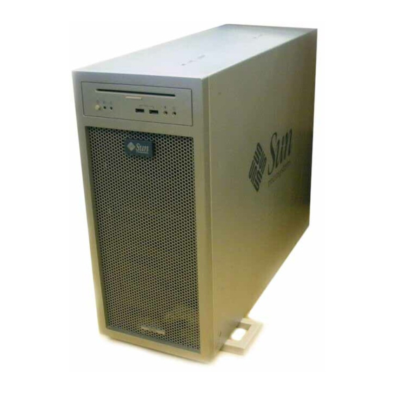
External System Description , and identify external components and connectors FIGURE 1-1 FIGURE 1-2 FIGURE 1-3 of the Sun Ultra 45 or Ultra 25 workstation. Monitor, Keyboard, Mouse, and Sun Ultra 45 or Ultra 25 Workstation FIGURE 1-1 Chapter 1 Product Description... -
Page 26: Figure 1-2 Front Panel Overview
Fault LED (not functional) none Workstation Status/Power LED (green) none Workstation Power button Audio connector, microphone (pink) Audio connector, headphone (lime green) USB 2.x connector (2) Sun Ultra 45 and Ultra 25 Workstations Service and Diagnostics Manual • May 2006... -
Page 27: Figure 1-3 Rear Panel Overview
Rear Panel Overview FIGURE 1-3 Sun Ultra 45 and Ultra 25 workstations Rear Panel Overview, TABLE 1-3 Callout in Rear Panel FIGURE 1-3 Part Description Symbol Audio connector, line in (light blue) Audio connector, line out (lime green) Serial 2 connector TTYB (DB-9) -
Page 28: Supported Sun Monitors
*Sun XVR-100 will not support two monitors at 1920 x 1200. For more information about the graphics accelerators, refer to: Sun XVR-100 Graphics Accelerator Installation Guide, 816-7560 Sun XVR-2500 Graphics Accelerator Installation and User’s Guide, 817-7517 Sun Ultra 45 and Ultra 25 Workstations Service and Diagnostics Manual • May 2006... -
Page 29: Preparing To Replace Components
Preparing to Replace Components This chapter describes common tasks that must be completed prior to performing a removal or installation procedure on any Sun Ultra 45 or Ultra 25 workstation. The procedures described in this chapter are written for workstation service providers and system administrators. -
Page 30: Safety Symbols
Follow all Sun standard cautions, warnings, and instructions marked on the equipment and described in Important Safety Information for Sun Hardware Systems, 816-7190. Follow the cautions, warnings, and instructions in the Sun Ultra 45 and Ultra 25 Workstations Safety and Compliance Guide, 819-2785. The document is available from: http://www.sun.com/documentation/... -
Page 31: Required Tools
Following this caution equalizes all electrical potentials with the workstation. Required Tools Use the following tools to service the Sun Ultra 45 or Ultra 25 workstations FIGURE 2-1 No. 2 Phillips screwdriver No. 0 Phillips screwdriver... -
Page 32: Powering Off The Workstation
For more information, refer to the documentation for the operating system in use. 4. Power off and disconnect any peripherals ( FIGURE 2-3 5. Disconnect the keyboard, mouse, monitor, and network connections. Sun Ultra 45 and Ultra 25 Workstations Service and Diagnostics Manual • May 2006... -
Page 33: Figure 2-2 Power Button And Sleep Key Location
Power Button and Sleep Key Location FIGURE 2-2 Disconnecting the Workstation Cables FIGURE 2-3 Chapter 2 Preparing to Replace Components... -
Page 34: Opening The Workstation
7. If necessary, remove any long PCI cards and pull the fan tray out of the chassis. 8. Find your removal or replacement procedure ( TABLE 2-1 Sun Ultra 45 and Ultra 25 Workstations Service and Diagnostics Manual • May 2006... -
Page 35: Finding Replacement Procedures
Removing the Side Cover and Access Panel FIGURE 2-4 Finding Replacement Procedures Identify the component that you need to replace in and refer to FIGURE 2-5 TABLE 2-1 to find the replacement procedure. Chapter 2 Preparing to Replace Components... -
Page 36: Figure 2-5 Major Workstation Components
Major Workstation Components FIGURE 2-5 Sun Ultra 45 and Ultra 25 Workstations Service and Diagnostics Manual • May 2006... -
Page 37: Table 2-1 Sun Ultra 45 Or Ultra 25 Workstation Replaceable Components
Sun Ultra 45 or Ultra 25 Workstation Replaceable Components TABLE 2-1 Item Animated Component Description Replacement Procedure Procedure? DVD-dual drive Slot loading DVD-dual drive with one “Replacing the I/O Module and cable combined cable for power and signal With the DVD-Dual Drive and Audio USB Board”... - Page 38 Consult your authorized Sun sales representative or service provider to confirm a part number prior to ordering a replacement component, or search this web site: http://www.sun.com/ibb/spares/ 2-10 Sun Ultra 45 and Ultra 25 Workstations Service and Diagnostics Manual • May 2006...
-
Page 39: Replacing The Motherboard And Associated Components
“Preparing to Replace Components” on page 2-1 before you perform any replacement procedure. Additional cautions, warnings, and instructions are provided in the Sun Ultra 45 and Ultra 25 Workstations Safety and Compliance Guide, 819-2785. The document is available from: http://www.sun.com/documentation/... -
Page 40: Motherboard Connector Overview
Motherboard Connector Overview show the connections for some cables and devices that FIGURE 3-1 FIGURE 3-2 connect to the motherboard. not used Motherboard With Component Connections FIGURE 3-1 Sun Ultra 45 and Ultra 25 Workstations Service and Diagnostics Manual • May 2006... -
Page 41: Replacing The Dimms
Motherboard Cables and Cable Clips FIGURE 3-2 Replacing the DIMMs This section describes removal and installation of the memory modules. Caution – DIMM memory is installed in pairs. If you replace a single DIMM, the new DIMM must be identical to the DIMM that you removed. Caution –... -
Page 42: Dimm Configuration Rules
DIMM Configurations for Single-CPU Workstations FIGURE 3-3 Note – The Ultra 25 workstation has one CPU (CPU0) and one bank of four DIMM slots on the motherboard. Sun Ultra 45 and Ultra 25 Workstations Service and Diagnostics Manual • May 2006... -
Page 43: Figure 3-4 Dimm Configurations For Ultra 45 Dual-Cpu Workstations
DIMM Configurations for Ultra 45 Dual-CPU Workstations FIGURE 3-4 Chapter 3 Replacing the Motherboard and Associated Components... -
Page 44: Openboot Prom Memory Message
The workstation must have at least one functional pair of DIMMs to display a message. A workstation with more than one pair of DIMMs might display more than one message. Sun Ultra 45 and Ultra 25 Workstations Service and Diagnostics Manual • May 2006... -
Page 45: Removing The Dimms
3.2.3 Removing the DIMMs 1. Power off the system and attach an antistatic wrist strap. Open and position the chassis, and remove the access panel. Refer to “Powering Off the Workstation” on page 2-4. 2. Release the DIMM by simultaneously pressing down on both ejector levers at the ends of the DIMM slot ( FIGURE 3-5 DIMM connector key... -
Page 46: Installing The Dimms
FIGURE 3-4 minimum of one pair of matching DIMMs. The minimum OpenBoot Prom level for the Sun Ultra 45 or Ultra 25 workstations is OpenBoot 4.21.x. Before installing Sun Ultra 45 and Ultra 25 memory, verify that the latest versions of OpenBoot PROM, system firmware, and recommended system patches are installed on your system. -
Page 47: Replacing The Battery
3. Review the recommended DIMM installation and configurations before installing the DIMM. See “Replacing the DIMMs” on page 3-3. Caution – If you replace a single DIMM, the replacement DIMM must be identical to the DIMM that you removed. 4. Align the DIMM notch to the DIMM connector key ( FIGURE 3-5 5. -
Page 48: Removing The Battery
FIGURE 3-6 3. Remove the battery. Battery clip Removing and Installing the Battery FIGURE 3-6 Note – The workstation does not function without the battery. 3-10 Sun Ultra 45 and Ultra 25 Workstations Service and Diagnostics Manual • May 2006... -
Page 49: Installing The Battery
3.3.2 Installing the Battery The battery fits directly into a socket on the motherboard. There are no additional fasteners or cables. 1. Position the battery over the battery socket with the plus (+) side up ( FIGURE 3-6 2. Press the battery down into the socket until the battery clicks into place. 3. -
Page 50: Installing The Nvram
2. Align the NVRAM key to the NVRAM connector key on the motherboard FIGURE 3-7 3. Press the NVRAM down into the connector. 4. Ensure that the NVRAM is tight in its connector. 3-12 Sun Ultra 45 and Ultra 25 Workstations Service and Diagnostics Manual • May 2006... -
Page 51: Replacing The Pci Cards
5. If you are finished working, reassemble the workstation, power on the workstation, and verify the NVRAM installation. Refer to “Finishing Component Replacement” on page 6-1 and “Verifying Component Installation” on page 6-5. Replacing the PCI Cards This section describes removal and installation of PCI cards in the workstation. 3.5.1 Identifying the PCI Cards There are five PCI connectors on the system motherboard. -
Page 52: Removing A Pci Card
Caution – If you are removing a graphics accelerator from a PCI-Express connector, be sure that you release the PCI-E connector latch ( FIGURE 3-9 3-14 Sun Ultra 45 and Ultra 25 Workstations Service and Diagnostics Manual • May 2006... -
Page 53: General Pci Card Guidelines
3. Gently rock the PCI card forward, then lift it straight out of the PCI card slot, and set it aside on an antistatic mat. Removing the PCI Card FIGURE 3-9 4. If you are not installing another PCI card in the empty slot, insert a filler panel into the rear panel slot. -
Page 54: Installation Considerations For Graphics Accelerators
This example configures the Sun XVR-100 graphics accelerator to be the new console display. 1. Obtain the ok prompt. See “Obtaining the ok Prompt” on page 10-2. 3-16 Sun Ultra 45 and Ultra 25 Workstations Service and Diagnostics Manual • May 2006... - Page 55 2. Display the device nodes for the installed graphics accelerators. For example: ok show-displays a) /pci@1f,700000/SUNW,XVR-2500@0 /pci@1e,600000/pci@0/pci@9/pci@0,2/ SUNW,XVR-100@2 q) NO SELECTION 3. Select the graphics accelerator to be the new console display by typing its respective letter. For example: Enter Selection, q to quit: b The utility ends and the device node path is loaded into a text buffer.
-
Page 56: Installing A Pci Card
PCI card slots. Read the documentation that came with the PCI card and see “General PCI Card Guidelines” on page 3-15. Installing a PCI Card FIGURE 3-10 3-18 Sun Ultra 45 and Ultra 25 Workstations Service and Diagnostics Manual • May 2006... - Page 57 3. Using a No. 2 Phillips screwdriver, remove the chassis filler panel from the PCI card slot and set the screw aside in a container ( FIGURE 3-10 Remove a second filler panel if needed for dual-width PCI cards. 4. Remove the new PCI card from its antistatic container. Caution –...
-
Page 58: Replacing The Motherboard
Note – If you have software that is licensed to the HostID or Ethernet address, you should install the old NVRAM on the new motherboard. 5. Remove all cables from the cable clips ( FIGURE 3-11 3-20 Sun Ultra 45 and Ultra 25 Workstations Service and Diagnostics Manual • May 2006... -
Page 59: Figure 3-11 Removing Components From The Motherboard
Removing Components from the Motherboard FIGURE 3-11 Chapter 3 Replacing the Motherboard and Associated Components 3-21... -
Page 60: Figure 3-12 Disconnecting Motherboard Cables
Power supply cables at connectors J22, J28, J45 (P1, P2, and P5) Hard drive signal cable connector J42 Disconnecting Motherboard Cables FIGURE 3-12 7. Turn the motherboard latch 90 degrees counterclockwise ( FIGURE 3-13 3-22 Sun Ultra 45 and Ultra 25 Workstations Service and Diagnostics Manual • May 2006... -
Page 61: Installing The Motherboard
Motherboard handle Motherboard handle Motherboard latch Releasing the Motherboard Latch FIGURE 3-13 8. Move the cables out of the way. 9. Using the motherboard handles, tilt the motherboard to one side and lift it until it is free of the chassis ( FIGURE 3-13 10. - Page 62 Fan tray backplane cable at connector J20 Power supply cables at connectors J22, J28, and J45 (P1, P2, and P5) Hard drive signal cable connector J42 3-24 Sun Ultra 45 and Ultra 25 Workstations Service and Diagnostics Manual • May 2006...
-
Page 63: Figure 3-14 Reconnecting Cables To The Motherboard
DVD-dual drive I/O module J22 (P2) J28 (P1) Fan tray backplane (not used) J45/P5 Power supply Hard drive backplane Reconnecting Cables to the Motherboard FIGURE 3-14 8. Secure the cables into the cable clips ( FIGURE 3-14 9. If necessary, install the old NVRAM onto the new motherboard ( FIGURE 3-15 Refer to “Replacing the NVRAM”... - Page 64 PCI cards are properly seated and secured. 12. Reassemble the workstation, power on the system, and verify the motherboard installation. Refer to “Finishing Component Replacement” on page 6-1. 3-26 Sun Ultra 45 and Ultra 25 Workstations Service and Diagnostics Manual • May 2006...
-
Page 65: Figure 3-15 Installing The Motherboard And Related Components
Installing the Motherboard and Related Components FIGURE 3-15 Chapter 3 Replacing the Motherboard and Associated Components 3-27... - Page 66 3-28 Sun Ultra 45 and Ultra 25 Workstations Service and Diagnostics Manual • May 2006...
-
Page 67: Replacing Storage Devices
“Preparing to Replace Components” on page 2-1 before you perform any replacement procedure. Additional cautions, warnings, and instructions are provided in the Sun Ultra 45 and Ultra 25 Workstations Safety and Compliance Guide 819-2785. The document is available from: http://www.sun.com/documentation. -
Page 68: Replacing A Hard Drive
3. Grasp the hard drive handle and pull the hard drive out of the hard drive bay. 4. Set the hard drive aside on an antistatic mat. Sun Ultra 45 and Ultra 25 Workstations Service and Diagnostics Manual • May 2006... -
Page 69: Installing A Hard Drive
HDD0 Removing the Hard Drive FIGURE 4-1 4.1.2 Installing a Hard Drive Caution – Use proper ESD grounding technique when handling components. Wear an antistatic wrist strap and use an antistatic mat. Store ESD-sensitive components in antistatic bags before placing them on any surface. 1. -
Page 70: Replacing The Hard Drive Backplane And Cables
1. Power off the system and attach an antistatic wrist strap. Open and position the chassis, and remove the access panel. Refer to “Powering Off the Workstation” on page 2-4. Sun Ultra 45 and Ultra 25 Workstations Service and Diagnostics Manual • May 2006... -
Page 71: Figure 4-2 Disconnecting The Cables From The Hard Drive Backplane
Disconnecting the Cables From the Hard Drive Backplane FIGURE 4-2 2. Remove all hard drives. See “Replacing a Hard Drive” on page 4-2. 3. Remove long PCI cards if they are covering the hard drive backplane cables. Refer to “Removing a PCI Card” on page 3-14. Set these components onto an antistatic mat. -
Page 72: Installing The Hard Drive Backplane And Cables
Refer to “Powering Off the Workstation” on page 2-4. 2. Open the I/O cable clip at the top of the chassis ( FIGURE 4-3 3. Disconnect the following cables: Sun Ultra 45 and Ultra 25 Workstations Service and Diagnostics Manual • May 2006... -
Page 73: Figure 4-3 Removing The I/O Module With The Dvd-Dual Drive And Audio Usb Board
Audio and power cable at J3 on the motherboard DVD cable at J11 on the motherboard USB cable from at J36 on the motherboard. New cables are provided with the DVD-dual drive and the I/O module. If you need to remove a long PCI card to access the USB cable, refer to “Removing a PCI Card”... -
Page 74: Installing The I/O Module And Dvd-Dual Drive
Section 3.5.5, “Installing a PCI Card” on page 3-18. Note – Always use the new cables that are shipped with the DVD-dual drive or I/O module. Sun Ultra 45 and Ultra 25 Workstations Service and Diagnostics Manual • May 2006... -
Page 75: Figure 4-4 Securing The Audio Usb Cables In The I/O Cable Clip
6. Guide the DVD and audio/power cables through the I/O cable clip at the top of the chassis and close the clip. 7. Reconnect the audio and USB cables to: Audio and power cable at J3 on the motherboard and J0201 on the audio USB board ( FIGURE 4-3 FIGURE 4-4... - Page 76 Note – Boot the system with the -r option, so that the Solaris Operating System can reconfigure itself for the new component. Refer to “Finishing Component Replacement” on page 6-1. 4-10 Sun Ultra 45 and Ultra 25 Workstations Service and Diagnostics Manual • May 2006...
-
Page 77: Replacing Chassis Components
“Preparing to Replace Components” on page 2-1 before you perform any replacement procedure. Additional cautions, warnings, and instructions are provided in the Sun Ultra 45 and Ultra 25 Workstations Safety and Compliance Guide, 819-2785. The document is available from: http://www.sun.com/documentation. -
Page 78: Removing The Fan Tray Backplane
Refer to “Powering Off the Workstation” on page 2-4. 2. Using the handle, pull the fan tray from the chassis and set it aside. Fan tray handle Removing the Fan Tray FIGURE 5-1 Sun Ultra 45 and Ultra 25 Workstations Service and Diagnostics Manual • May 2006... -
Page 79: Installing The Fan Tray And Fan Tray Backplane
5.1.2 Removing the Fan Tray Backplane 1. Disconnect the fan tray backplane from the motherboard at connector J20 FIGURE 5-1 2. Using a No. 2 Phillips screwdriver, remove the screws for the fan tray backplane. Removing the Fan Tray Backplane FIGURE 5-2 5.1.3 Installing the Fan Tray and Fan Tray Backplane... -
Page 80: Replacing The Power Supply
1. If necessary, remove any long PCI cards that are blocking the cables. Place the PCI card on an antistatic mat. 2. Remove the fan tray. Sun Ultra 45 and Ultra 25 Workstations Service and Diagnostics Manual • May 2006... -
Page 81: Figure 5-3 Removing The Power Supply
Removing the Power Supply FIGURE 5-3 3. Squeeze the power supply connector clip to disconnect the following cables from the motherboard ( FIGURE 5-3 P2 power cable on the motherboard (J22) P1 power cable on the motherboard at (J28) P5 power supply signal cable on the motherboard (J45) 4. -
Page 82: Installing The Power Supply
2. Align the power supply IEC-320 connector so that the power cord socket is nearest the left rear of the chassis, when viewed from the back ( FIGURE 5-4 Sun Ultra 45 and Ultra 25 Workstations Service and Diagnostics Manual • May 2006... -
Page 83: Figure 5-4 Installing The Power Supply
Installing the Power Supply FIGURE 5-4 3. Guide the cables and push the power supply into the chassis opening until the back of the power supply aligns with the back of the chassis. 4. Tighten the captive screw that secures the power supply to the chassis ( FIGURE 5-4 5. -
Page 84: Figure 5-5 Power Supply Cable Connections At Motherboard And Hard Drive Backplane
6. Inspect the power supply fasteners to verify that: The power supply push bar is seated. The power supply captive screw is tight. 7. Inspect the power supply cabling to verify that: Sun Ultra 45 and Ultra 25 Workstations Service and Diagnostics Manual • May 2006... - Page 85 The three power supply cables are firmly connected to the motherboard at P1, P2, and P5 (J45). The hard drive backplane power cable is firmly connected at J4. The hard drive backplane signal cable is securely connected at both ends and is routed over the other cables.
- Page 86 5-10 Sun Ultra 45 and Ultra 25 Workstations Service and Diagnostics Manual • May 2006...
-
Page 87: Finishing Component Replacement
C H A P T E R Finishing Component Replacement This chapter describes how to finish the replacement of internal workstation replaceable components, close the system, and prepare it for operation. Topics covered in this chapter are: Section 6.1, “Reassembling the Workstation” on page 6-1 Section 6.2, “Verifying Component Installation”... -
Page 88: Figure 6-1 Reassembling The Workstation
8. Reconnect the keyboard, mouse, monitor, network connections, and any peripherals ( FIGURE 6-2 9. Reconnect the power cord to the workstation and the power source. Sun Ultra 45 and Ultra 25 Workstations Service and Diagnostics Manual • May 2006... -
Page 89: Figure 6-2 Reconnecting The Cables
Reconnecting the Cables FIGURE 6-2 10. Power on any connected peripherals or monitors. Note – The monitor must be powered on before the workstation so that the monitor can communicate with the graphics accelerator when the workstation powers on. 11. Power on the workstation. Chapter 6 Finishing Component Replacement... -
Page 90: Figure 6-3 Powering On The Workstation
Solaris OS finds the new component. For example: # reboot -- If you are at the ok prompt, type: ok boot -r Sun Ultra 45 and Ultra 25 Workstations Service and Diagnostics Manual • May 2006... -
Page 91: Verifying Component Installation
Verifying Component Installation There are several methods for verifying the installation of the new component. 6.2.1 Reconfiguring the System With boot -r Option 1. Boot the system with the -r option, so that the Solaris OS can reconfigure itself for the new component. For example: # boot -- -r 2. - Page 92 Sun Ultra 45 and Ultra 25 Workstations Service and Diagnostics Manual • May 2006...
-
Page 93: Diagnostics Overview
Section 7.3, “Power-On Sequence” on page 7-6 Diagnostic Tools Available The Sun Ultra 45 and Ultra 25 Workstations Service and Diagnostics Manual uses displayed messages, system sounds, flowcharts, and firmware and software diagnostic tools to help you locate and identify workstation malfunctions. -
Page 94: Diagnostic Tests
The Predictive Self-Healing (predictive self-healing tools) is often your first and best tool for diagnostics. Use to determine which diagnostic program to use to TABLE 7-2 troubleshoot a component. Sun Ultra 45 and Ultra 25 Workstations Service and Diagnostics Manual • May 2006... -
Page 95: Table 7-2 Diagnostics Tools Sorted By Component
Diagnostics Tools Sorted by Component TABLE 7-2 Solaris 10 Predictive Component Self-Healing POST OpenBoot Diagnostics SunVTS Diagnoses events and Tests workstation core Diagnoses system Exercises and stresses prescribes corrective components such as motherboard and workstation actions. CPU and memory. component interfaces. components. -
Page 96: Diagnostics Hierarchy
* More thorough test results are possible with a loopback connector, however these results are not included in this document. 7.2.1 Diagnostics Hierarchy One approach to diagnostics is shown in FIGURE 7-1 FIGURE 7-2 Sun Ultra 45 and Ultra 25 Workstations Service and Diagnostics Manual • May 2006... -
Page 97: Figure 7-1 Diagnostic Method Flow Chart
Diagnostic Method Flow Chart FIGURE 7-1 Chapter 7 Diagnostics Overview... -
Page 98: Power-On Sequence
Diagnostics Method Flow Chart – Traditional Data Collection FIGURE 7-2 Power-On Sequence When you power on the Sun Ultra 45 or Ultra 25 workstation, a series of processes brings the workstation to a user-ready state. The sequence of power-on events is shown below: 1. - Page 99 4. OpenBoot PROM loads device drivers. 5. OpenBoot PROM loads workstation configuration from NVRAM. 6. OpenBoot PROM probes PCI bus. 7. OpenBoot PROM loads OpenBoot Diagnostics. 8. OpenBoot PROM loads and executes boot block. 9. Boot block loads and executes bootstrap program. Note –...
- Page 100 Sun Ultra 45 and Ultra 25 Workstations Service and Diagnostics Manual • May 2006...
-
Page 101: Basic Diagnostics
C H A P T E R Basic Diagnostics This chapter provides basic diagnostics assistance. Topics include: Section 8.1, “LED Diagnostics” on page 8-1 Section 8.2, “Audio Diagnostics” on page 8-2 Section 8.3, “Display Diagnostics” on page 8-2 LED Diagnostics This section describes LEDs that you can use to diagnose the workstation. -
Page 102: Audio Diagnostics
For example: Sun XVR-2500 Graphics Accelerator Installation and User’s Guide, 817-7517 The graphics accelerator documentation is available at this web site. http://www.sun.com/documentation/ Sun Ultra 45 and Ultra 25 Workstations Service and Diagnostics Manual • May 2006... -
Page 103: Solaris 10 Predictive Self-Healing And Solaris Diagnostics
C H A P T E R Solaris 10 Predictive Self-Healing and Solaris Diagnostics This chapter provides information about the following topics: Section 9.1, “Predictive Self-Healing Overview” on page 9-1 Section 9.2, “Predictive Self-Healing Tools” on page 9-2 Section 9.3, “Using the Predictive Self-Healing Commands” on page 9-3 Section 9.4, “Determining Which Diagnostics Tools to Use”... -
Page 104: Predictive Self-Healing Tools
AUTO-RESPONSE: What, if Nov 1 16:30:20 dt88-292 AUTO-RESPONSE: One or more anything, the system did to device instances may be disabled alleviate any follow-on issues Sun Ultra 45 and Ultra 25 Workstations Service and Diagnostics Manual • May 2006... -
Page 105: Using The Predictive Self-Healing Commands
System Generated Predictive Self-Healing Message TABLE 9-1 Output Displayed Description IMPACT: A description of what Nov 1 16:30:20 dt88-292 IMPACT: Loss of services that response may have done provided by the device instances associated with this fault REC-ACTION: A short description Nov 1 16:30:20 dt88-292 REC-ACTION: Schedule a repair of what the system administrator procedure to replace the affected device. -
Page 106: Fmdump -V Command
Solaris Fault Manager. The fmadm faulty command is primarily used to determine the status of a component involved in a fault. Sun Ultra 45 and Ultra 25 Workstations Service and Diagnostics Manual • May 2006... -
Page 107: Fmadm Config Command
# fmadm faulty STATE RESOURCE / UUID -------- ------------------------------------------------------------- degraded dev:////pci@1e,600000 0ee65618-2218-4997-c0dc-b5c410ed8ec2 The PCI device is degraded and is associated with the same UUID as seen above. You may also see “faulted” states. 9.3.2.1 fmadm config Command The fmadm config command output shows you the version numbers of the diagnosis engines in use by your system, as well as their current state. -
Page 108: Determining Which Diagnostics Tools To Use
“ping Command” on page 9-12 “ps Command” on page 9-13 “prstat Command” on page 9-15 Most of these commands are located in the /usr/bin or /usr/sbin directories. Sun Ultra 45 and Ultra 25 Workstations Service and Diagnostics Manual • May 2006... -
Page 109: Iostat Command
The iostat command iteratively reports terminal, drive, and tape I/O activity, as well as CPU utilization. 9.5.1.1 Options describes options for the iostat command and how those options can TABLE 9-2 help troubleshoot the Sun Ultra 45 or Ultra 25 workstation. Options for iostat TABLE 9-2 Option Description... -
Page 110: Prtdiag Command
AC lists fan status, temperatures, ASIC, and PROM revisions. power failure, the most recent hardware fatal error information, and (if applicable) environmental status. Sun Ultra 45 and Ultra 25 Workstations Service and Diagnostics Manual • May 2006... -
Page 111: Prtconf Command
Similar to the show-devs command run at the ok prompt, the prtconf command displays the devices that are configured for the Sun Ultra 45 or Ultra 25 workstation. The prtconf command identifies hardware that is recognized by the Solaris OS. If... -
Page 112: Table 9-4 Options For Prtconf
(driver not attached) chosen (driver not attached) openprom (driver not attached) client-services (driver not attached) options, instance #0 aliases (driver not attached) . . . 9-10 Sun Ultra 45 and Ultra 25 Workstations Service and Diagnostics Manual • May 2006... -
Page 113: Options
Command The netstat command displays the network status. 9.5.4.1 Options describes options for the netstat command and how those options can TABLE 9-5 help troubleshoot the Sun Ultra 45 or Ultra 25 workstation. Options for netstat TABLE 9-5 Option Description... -
Page 114: Options
Forces the probe packet to By identifying different routes to the target host, those route through a specified individual routes can be tested for quality. gateway. 9-12 Sun Ultra 45 and Ultra 25 Workstations Service and Diagnostics Manual • May 2006... -
Page 115: Ps Command
Command The ps command lists the status of system processes. Using options and rearranging the command output can assist in determining the Sun Ultra 45 or Ultra 25 workstation resource allocation. Chapter 9 Solaris 10 Predictive Self-Healing and Solaris Diagnostics... -
Page 116: Options
Note – When using sort with the option, the column headings are printed so that the value in the first column is equal to zero. 9-14 Sun Ultra 45 and Ultra 25 Workstations Service and Diagnostics Manual • May 2006... -
Page 117: Prstat Command
9.5.7.1 Options describes options for the prstat command and how those options can TABLE 9-8 help troubleshoot the Sun Ultra 45 or Ultra 25 workstation. Options for prstat TABLE 9-8 Option Description... - Page 118 9-16 Sun Ultra 45 and Ultra 25 Workstations Service and Diagnostics Manual • May 2006...
-
Page 119: Nvram
C H A P T E R NVRAM The Sun Ultra 45 and Ultra 25 workstation motherboards use a nonvolatile random access memory module (NVRAM) that stores parameters used for configuring system startup ( ). The NVRAM module uses a SEEPROM chip. -
Page 120: Obtaining The Ok Prompt
10.1 Obtaining the ok Prompt When a Sun Ultra 45 or Ultra 25 workstation is put into run level state 0, the ok prompt is displayed. At the ok prompt, you can make changes to the NVRAM and conduct OpenBoot PROM tests (POST and OpenBoot Diagnostics). -
Page 121: Changing Nvram Configuration Parameter Values
Parameter Values The NVRAM configuration parameter values set the startup behavior of the Sun Ultra 45 or Ultra 25 workstation. Changes made to the variables typically survive power cycling and if not configured properly, might have an adverse affect. Use discretion when changing or resetting NVRAM configuration parameter values. - Page 122 No default security-password No default security-#badlogins No default verbosity diag-trigger none none service-mode? false false diag-script normal normal diag-level diag-switch? false false 10-4 Sun Ultra 45 and Ultra 25 Workstations Service and Diagnostics Manual • May 2006...
-
Page 123: Configuration Parameter Default Values
To change a parameter value, use the setenv command. For example: ok setenv diag-switch? true This example enables diagnostics. Note – Parameters that end with a question mark (?) can only be set true or false. 10.2.2 Configuration Parameter Default Values Typing set-defaults resets all parameters to their default values. - Page 124 No default Value of min provides almost no output during diagnostics. verbosity Reserved. diag-trigger none Reserved. service-mode? false Name of the diagnostics script. diag-script none 10-6 Sun Ultra 45 and Ultra 25 Workstations Service and Diagnostics Manual • May 2006...
-
Page 125: Setting Nvram Security Mode
NVRAM Configuration Parameter Default Values (Continued) TABLE 10-3 Parameter Default Value Description Value of max enables enhanced diagnostics. diag-level Value of false disables diagnostics under the OpenBoot diag-switch? false PROM. Arguments used by the PROM for booting the network. network-boot-arguments none More information about the NVRAM configuration parameters is available from the eeprom man page. - Page 126 10 seconds until authorization can be re- attempted. For example: > printenv Firmware Password: Sorry. Waiting 10 seconds. > 10-8 Sun Ultra 45 and Ultra 25 Workstations Service and Diagnostics Manual • May 2006...
-
Page 127: Eeprom Command
10.4 eeprom Command It is possible to display and change NVRAM configuration parameters from the Solaris OS by using the eeprom command. The eeprom command is executed by superuser in the form of: # eeprom parameter=value If no parameter is specified, the eeprom command displays only the current NVRAM configuration parameter values, similar to the printenv command. -
Page 128: Stop-A Key Sequence
Use the Stop-A key sequence to abort an OpenBoot process. To issue the Stop-A key sequence for the Sun Ultra 45 or Ultra 25 workstation, press both the Stop and A keys (Stop-A) immediately after powering on the workstation. Hold both keys down until the workstation beeps. -
Page 129: Table 10-5 Stop-N Equivalent Configuration Parameters
Note – Once the Power button LED stops flashing and stays lit, pressing the Power button again powers off the system. A screen similar to the following is displayed to indicate that you have successfully reset NVRAM contents to the default values and the system is in Safe NVRAM mode. -
Page 130: Resetting The Nvram Permanently
(power-off) state. To restart the workstation, you must manually press the Power button, which initiates the boot process. 10-12 Sun Ultra 45 and Ultra 25 Workstations Service and Diagnostics Manual • May 2006... -
Page 131: Power-On Self-Test
C H A P T E R Power-On Self-Test This chapter describes the power-on self-test Sun Ultra 45 and Ultra 25 workstation (POST). Topics covered are: Section 11.1, “POST Overview” on page 11-1 Section 11.2, “post Command” on page 11-2 Section 11.3, “POST Output”... -
Page 132: Post Command
If no diagnostic level or output verbosity is provided, the post command uses the NVRAM settings for diag-level and verbosity. See “Changing NVRAM Configuration Parameter Values” on page 10-3 for more information about these parameters. 11-2 Sun Ultra 45 and Ultra 25 Workstations Service and Diagnostics Manual • May 2006... -
Page 133: Diagnostic Levels
11.2.1 Diagnostic Levels You can set the following diagnostic levels with POST. post min normal post min min post min max post max normal post max min post max max summarizes the tests performed at min and max diagnostic levels. TABLE 11-3 Tests Performed at min and max Diagnostic Levels TABLE 11-3... -
Page 134: Post Output
Executing Power On Self Test Q0> POST build version and date is 0>@(#) Sun Ultra 45 POST 4.21.x 2005/10/13 16:57 displayed. POST build path is displayed. /dat/fw/common-source/firmware_re/post/post-build- 4.21.x/Ultra/Ultra45/integrated (firmware_re) 11-4 Sun Ultra 45 and Ultra 25 Workstations Service and Diagnostics Manual • May 2006... -
Page 135: 11.3.2 Post Max Max
Output Comparison (Continued) TABLE 11-5 Output Displayed What Is Happening Copyright and license are 0>Copyright © 2005 Sun Microsystems, Inc. All rights displayed. reserved SUN PROPRIETARY/CONFIDENTIAL. Use is subject to license terms. CPU0 is acknowledged and POST 0>OBP->POST Call with %o0=00000800.01012000. - Page 136 DMMU is set up. 0>Setup and Enable DMMU 0>Setup DMMU Miss Handler Mailbox region is checked and 0>Test Mailbox initialized in L2 cache. 0>Scrub Mailbox 11-6 Sun Ultra 45 and Ultra 25 Workstations Service and Diagnostics Manual • May 2006...
- Page 137 post max max Output Comparison (Continued) TABLE 11-6 Output Displayed What Is Happening Operation of TICK registers is 0>CPU Tick and Tick Compare Registers Test verified. Operation of STICK registers is 0>CPU Stick and Stick Compare Registers Test verified. Motherboard timing is to be 0>Set Timing configured.
- Page 138 0>Addr walk mem test on CPU 0 Bank 0: 00000000.00000000 to 00000000.80000000. Mailbox region is set in memory. 0>Set Mailbox Memory control register1 is set. 0>Final mc1 is 1000000a.1e581c61 11-8 Sun Ultra 45 and Ultra 25 Workstations Service and Diagnostics Manual • May 2006...
- Page 139 post max max Output Comparison (Continued) TABLE 11-6 Output Displayed What Is Happening Memory is allocated for POST. 0>Setup Final DMMU Entries Allocated memory is scrubbed 0>Post Image Region Scrub clean. POST is transferred from ROM to 0>Run POST from Memory RAM memory.
- Page 140 0>Non SPARC Atomic Instruction Test 0>SOFTINT Register and Interrupt Test 0>Branch Memory Test 0>Fast ECC test 0>System ECC test On-board SRAM is checked. 0>XBus SRAM 0>IO-Bridge Quick Read 0> 11-10 Sun Ultra 45 and Ultra 25 Workstations Service and Diagnostics Manual • May 2006...
- Page 141 post max max Output Comparison (Continued) TABLE 11-6 Output Displayed What Is Happening 0>-------------------------------------------------- ------------ 0>--------- IO-Bridge Quick Read Only of CSR and ID - --------- 0>-------------------------------------------------- ------------ 0>fire 1 JBUSID 00000400.0f000000 = 0> fc000002.f03dda23 0>-------------------------------------------------- ------------ 0>fire 1 JBUSCSR 00000400.0f410000 = 0>...
- Page 142 0>POST: Return to OBP. Error messages are reported when they are found. Examples of POST messages are shown in “Analyzing POST Messages” on page 11-14. 11-12 Sun Ultra 45 and Ultra 25 Workstations Service and Diagnostics Manual • May 2006...
-
Page 143: 11.3.3 Post Min Min
Probing memory Probing I/O buses Sun Ultra 45 , Keyboard present Copyright 1998-2005 Sun Microsystems, Inc. All rights reserved. OpenBoot 4.21.x, 1024 MB memory installed, Serial #53463596. Ethernet address 0:3:ba:2f:ca:2c, Host ID: 832fca2c. POST conducted the tests. No output was provided. Error messages are reported when they are found. -
Page 144: Analyzing Post Messages
DIMM0, Motherboard 0>Repair Instructions: Replace items in order listed by ’H/W under test’ above 0>MSG = Pin 72 failed on CPU0: Bank 0 DIMM0, Motherboard 0>END_ERROR 11-14 Sun Ultra 45 and Ultra 25 Workstations Service and Diagnostics Manual • May 2006... -
Page 145: Warning Messages
The DIMM in slot DIMM0 was at fault. Several other error messages were displayed, and a summary was provided: 0>ERROR: 0> POST top level status has the following failures: 0> CPU0: Bank 0 DIMM0, Motherboard 0> CPU0: Bank 1 DIMM0, Motherboard 0>END_ERROR The DIMM in slot DIMM0 should be replaced. -
Page 146: Info Messages
To execute POST and view its output, you must perform the procedures in the following sections. 11.5.1 Verifying the Baud Rate Ensure that the communication parameters are correct. Use one of the following procedures: 11-16 Sun Ultra 45 and Ultra 25 Workstations Service and Diagnostics Manual • May 2006... -
Page 147: Openboot Prom Level Procedure
11.5.3.1 Configuring a Serial Terminal You can view POST output through any VT-100 RS-232 compatible serial terminal. The terminal connects to the Sun Ultra 45 or Ultra 25 workstation at the TTYA port: TTY A Chapter 11 Power-On Self-Test 11-17... -
Page 148: Configuring A Second System
The following URL provides part numbers for adapters and other Sun cables. You must be a registered SunSolve user to access this URL. http://sunsolve.sun.com/handbook_pub/Devices/Cables/cables_ext_d ata.html 11-18 Sun Ultra 45 and Ultra 25 Workstations Service and Diagnostics Manual • May 2006... -
Page 149: Making A Tip Connection
DB-9F DB-9F or other To other serial TTY A port Crossover Cable Wiring Diagram FIGURE 11-1 11.5.3.3 Making a Tip Connection Making a Tip connection requires configuring the serial port of the second system and using the tip command. The following procedure configures for serial port 1, TTY A 1. -
Page 150: Running Post
11.6.0.1 OpenBoot PROM Level Procedure From the ok prompt of the system to run POST, type: ok setenv diag-switch? false ok setenv auto-boot? false 11-20 Sun Ultra 45 and Ultra 25 Workstations Service and Diagnostics Manual • May 2006... -
Page 151: Solaris Os Level Procedure
11.6.0.2 Solaris OS Level Procedure As superuser in a terminal window of the system to run POST, type: # eeprom diag-switch?=false # eeprom auto-boot?=false Chapter 11 Power-On Self-Test 11-21... - Page 152 11-22 Sun Ultra 45 and Ultra 25 Workstations Service and Diagnostics Manual • May 2006...
-
Page 153: Openboot Prom
Because the OpenBoot PROM software resides within the NVRAM, it is called firmware. The OpenBoot PROM plays a major role in starting the Sun Ultra 45 or Ultra 25 workstation (For details see: “Power-On Sequence” on page 7-6.) If an error occurs during that process, a message is usually displayed. -
Page 154: Openboot Prom Utilities
To use the OpenBoot PROM utilities you must first obtain the ok prompt. See “Obtaining the ok Prompt” on page 10-2. 12.2.1 show-devs Utility The show-devs utility displays the devices installed in the Sun Ultra 45 or Ultra 25 workstation recognized by the OpenBoot PROM. For example: ok show-devs /i2c@1f,464000... -
Page 155: Watch-Net Utility
Target 0 Unit 0 Disk HITACHI DK32EJ14NSUN146GPQ0B 286739329 Blocks, 140009 MB If no information regarding an installed device is displayed, check the cable connections inside of the Sun Ultra 45 or Ultra 25 workstation chassis. Chapter 12 OpenBoot PROM 12-3... -
Page 156: Probe-Ide Utility
12.2.4 probe-ide Utility The Sun Ultra 45 or Ultra 25 workstation DVD-dual drive is controlled by the IDE bus. The probe-ide utility displays the manufacturer and model of devices attached to the IDE buses. For example: ok probe-ide Device 0... -
Page 157: Watch-Clock Utility
The .version utility displays the software version of: OpenBoot PROM OpenBoot Diagnostics POST For example: ok .version Release 4.21.x created 2005/11/05 18:29 Sun Ultra 45 or Ultra 25 workstation OBP 4.21.x 2005/11/05 18:29 OBDIAG 4.21.x 2005/11/05 18:31 POST 4.21.x 2005/11/05 19:58 Chapter 12 OpenBoot PROM 12-5... -
Page 158: Openboot Diagnostics
The system restarts and the ok prompt is displayed again. 4. Set the diag-switch? property to true. Type: ok setenv diag-switch? true 5. Start OpenBoot Diagnostics. Type: ok obdiag 12-6 Sun Ultra 45 and Ultra 25 Workstations Service and Diagnostics Manual • May 2006... -
Page 159: Obdiag Menu
12.3.2 obdiag Menu Once started, OpenBoot Diagnostics polls the system for device nodes. If the device has a self-test, the device function can be verified. Some cards may not support self- test. When the poll is finished, OpenBoot Diagnostics lists a menu of the tests that can be executed. -
Page 160: Interpreting Openboot Diagnostics Tests
1. At the obdiag prompt, set the diagnostic passes to 1. Type: obdiag> setenv diag-passes 1 2. Set the diagnostic level to maximum. Type: obdiag> setenv diag-level max 12-8 Sun Ultra 45 and Ultra 25 Workstations Service and Diagnostics Manual • May 2006... -
Page 161: Initiating A Test
3. Set the diagnostics to be verbose and display subtest names during test execution. Type: obdiag> setenv test-args verbose,subtests These settings are stored in the NVRAM test-args parameter and survive power cycling. Note – The help command provides additional information for configuring OpenBoot Diagnostics. - Page 162 Testing /ebus@1f,464000/serial@2,0 ........passed Pass:1 (of 1) Errors:0 (of 0) Tests Failed:0 Elapsed Time: 0:0:0:18 Hit any key to return to the main menu serial port test. 12-10 Sun Ultra 45 and Ultra 25 Workstations Service and Diagnostics Manual • May 2006...
-
Page 163: Openboot Prom Messages
12.4 OpenBoot PROM Messages lists some common fault messages or portions of fault messages displayed TABLE 12-2 by the OpenBoot PROM, their meanings, and actions that you can take to resolve the message condition. OpenBoot PROM Messages and Their Meaning TABLE 12-2 Message Meaning... - Page 164 12-12 Sun Ultra 45 and Ultra 25 Workstations Service and Diagnostics Manual • May 2006...
-
Page 165: Sunvts
13.2 Installing SunVTS The SunVTS software is preinstalled on your Sun Ultra 45 or Ultra 25 workstation hard drive. Use only SunVTS 6.1 or subsequent compatible versions. You can find the latest revisions of SunVTS software on the web at: http://www.sun.com/oem/products/vts/... -
Page 166: Sunvts Documentation
SunVTS Test Reference Manual for SPARC Platforms, 819-2362, provides details about each SPARC SunVTS test. Sun VTS Reference Manual, 819-2364, provides the SunVTS man pages The SunVTS documentation is available at: http://www.sun.com/documentation/ 13-2 Sun Ultra 45 and Ultra 25 Workstations Service and Diagnostics Manual • May 2006... -
Page 167: Power Management
Environmental Protection Agency, the Sun Ultra 45 or Ultra 25 workstation power management features are enabled by default. Note – The Sun Ultra 25 workstation meets or exceeds Energy Star guidelines in operation only when using the Java™ Desktop System (Java DS) windowing system, not while running the Common Desktop Environment (CDE) windowing system. -
Page 168: Using Dtpower
No power management for any device. Before you configure power management, consider the way that you use the Sun Ultra 45 or Ultra 25 workstation. For example: is the workstation used as a server? If so, use only minimal power management, or none at all. -
Page 169: Modifying Power Management
LED will stop flashing. To reactivate the Sun Ultra 45 or Ultra 25 workstation from low-power mode, press the spacebar on the keyboard or move the mouse. If you are connected remotely, any system activity that you initiate can bring the workstation out of low-power mode. - Page 170 Sun Ultra 45 and Ultra 25 Workstations Service and Diagnostics Manual • May 2006...
-
Page 171: Product Specifications
17.520 in. 50 – 58 lbs 569.15 mm 205 mm 445 mm 22.67 – 26.30 kgs If the Sun Ultra 45 or Ultra 25 workstation is placed in an enclosure, be sure to allow adequate airflow from front to rear. -
Page 172: Figure B-1 Workstation Dimensions With Stabilizer Open
18.193 in Workstation Dimensions With Stabilizer Open FIGURE B-1 205 mm 8.07 in 569.15 mm 22.407 in 445 mm 17.52 in Workstation Dimensions Without Stabilizer FIGURE B-2 Sun Ultra 45 and Ultra 25 Workstations Service and Diagnostics Manual • May 2006... -
Page 173: Electrical Specifications
Electrical Specifications lists electrical specifications for the Sun Ultra 45 or Ultra 25 workstation. TABLE B-2 Electrical Specifications TABLE B-2 Maximum AC Input Voltage Current Frequency Range 1 100 VAC 12 amps 50 – 60 Hz Range 2 110 – 127 VAC 10 amps 50 –... -
Page 174: Environmental Requirements
5 G’s, 11 msec, half-sine 30 G’s, 11 msec, half-sine Vibration 0.2 G’s, 5 to 500 Hz swept-sine 1.0 G’s, 5 to 500 Hz swept-sine Handling 100 mm Drop Sun Ultra 45 and Ultra 25 Workstations Service and Diagnostics Manual • May 2006... -
Page 175: Functional Description
FIGURE C-1 and jumper locations. Note – The Sun Ultra 25 workstation motherboard has one CPU (CPU0) and one bank of four DIMM slots. Other aspects of the Sun Ultra 25 are the same as the Sun Ultra 45 workstation. -
Page 176: Figure C-1 Sun Ultra 45 Motherboard Diagram
PCI-E1 (x8 speed) J37 SAS / SATA back- PCI-E0 (x4 speed) plane PCI-X1 100 MHz PCI-X0 100MHz J45 Pwr supply data Sun Ultra 45 Motherboard Diagram FIGURE C-1 Sun Ultra 45 and Ultra 25 Workstations Service and Diagnostics Manual • May 2006... -
Page 177: System Block Diagram
FIGURE C-2 Note – The Sun Ultra 25 workstation motherboard has one CPU (CPU0) and one bank of four DIMM slots. Other aspects of the Sun Ultra 25 are the same as the Sun Ultra 45 workstation. Appendix C Functional Description... -
Page 178: Component Overview
PCI-E 0 short connector is 8 lane capable, running at 4 lanes C.1.3.4 I/O Subsystem UltraDMA ATA 133 controller AC-97 compliant audio interface USB 2.x interface Sun Ultra 45 and Ultra 25 Workstations Service and Diagnostics Manual • May 2006... -
Page 179: Gigabit Ethernet
FIGURE C-3 Note – The Sun Ultra 25 workstation motherboard has one CPU (CPU0) and one bank of four DIMM slots. Other aspects of the Sun Ultra 25 are the same as the Sun Ultra 45 workstation. Appendix C Functional Description... -
Page 180: Cpu Description
The UltraSPARC IIIi CPU supports full implementation of the 64-bit SPARC-V9 architecture, a 64-bit virtual address space, and a 43-bit physical address space. The core instruction set includes graphics instructions that provide the most common Sun Ultra 45 and Ultra 25 Workstations Service and Diagnostics Manual • May 2006... -
Page 181: Memory Controller
Note – DIMMs must always be installed in pairs. A memory controller sends requests in the pipeline, using 16 memory banks in the Sun Ultra 45 when fully loaded, and 8 memory banks in the Sun Ultra 25 when fully loaded. -
Page 182: Serial Ports
The Sun Ultra 45 or Ultra 25 workstation has two serial ports. When powering off, the Sun Ultra 45 or Ultra 25 workstation sends a Break signal out the serial ports. This break could interfere with a workstation-controlled server if the server is operating through a Tip connection. -
Page 183: Disabling The Keyboard Abort On The Server
protocol. If the workstation sends the BREAK signal, it is ignored by the network terminal concentrator. Additionally, the concentrator does not send the BREAK signal upon powering off. C.3.3 Disabling the Keyboard Abort on the Server This procedure configures the server to ignore the BREAK signal. As superuser, open a terminal window and disable the keyboard abort. -
Page 184: Permanently Disabling The Keyboard Abort Or Configuring An Alternate Break Key Sequence On The Server
#KEYBOARD_ABORT=disable To configure the alternate BREAK key sequence, uncomment this line: #KEYBOARD_ABORT=alternate 2. Save the file. 3. Reinitialize the kbd drivers. Type: # kbd -i C-10 Sun Ultra 45 and Ultra 25 Workstations Service and Diagnostics Manual • May 2006... -
Page 185: Glossary
Glossary address (1) A number used by system software to identify a data storage location. (2) In networking, a unique code that identifies a node to the network. ASIC Application-specific integrated circuit. Advanced Technology Attachment. See also SATA. A bank can be: bank (1) Interleaving within a single device on a DDR1 SDRAM. - Page 186 Mounting hardware used to secure hard drives and other peripherals inside the workstation. D-TLB Data translation look-aside buffer. DVD-dual Optical drive that can read and write DVDs and CDs. Glossary-2 Sun Ultra 45 and Ultra 25 Workstations Service and Diagnostics Manual • May 2006...
- Page 187 DVD-ROM Digital versatile disc read-only memory. Error checking and correction. The detection and correction of all single-bit errors, plus the detection of double-bit and some multiple-bit errors. Extended capabilities port. EEPROM Electrically erasable programmable read only memory. Electromagnetic interference. An electrical characteristic that directly or indirectly contributes to a degradation in performance of an electronic system.
- Page 188 L2 cache Level 2 cache. Local area network. leaf Any node (location in a tree structure) that is farthest from the primary node. Light-emitting diode. Glossary-4 Sun Ultra 45 and Ultra 25 Workstations Service and Diagnostics Manual • May 2006...
- Page 189 Media access controller. See also PHY. Mbit (Mb) Megabit. 1,048,576 bits. MByte (MB) Megabyte. One million bytes. Mbps Megabits per second. Memory controller unit. Megahertz. One million cycles per second. Media independent interface. Multiplex, multiplexer. A multiplexer merges information from multiple signals to a single channel.
- Page 190 RISC Reduced instruction set computer. A computer using the RISC architecture. Serial attached SCSI. SATA Serial ATA. Small computer system interface. SCSI Single data rate. Glossary-6 Sun Ultra 45 and Ultra 25 Workstations Service and Diagnostics Manual • May 2006...
- Page 191 SDRAM Synchronous DRAM. SEEPROM Serial electrically erasable programmable read only memory. SMBus System management bus. The SMBus protocol is a subset of the I C protocol. smart card A card used for user authentication or storing individual user preferences. A search for the latest data in memory. snoop Southbridge A highly integrated system I/O chip.
- Page 192 Voltage at the common collector (positive [+] electrical connection). Glossary-8 Sun Ultra 45 and Ultra 25 Workstations Service and Diagnostics Manual • May 2006...
- Page 193 Index crossover diagram, 11-18 DVD-dual drive, disconnecting, 4-7, 4-9 antistatic mat and wrist strap, 2-3 hard drive backplane, installing, 4-6 audio hard drive backplane, replacing, 4-4 responses, 8-2 motherboard, reconnecting, 3-24 SunVTS, 13-1 Tip diagram, 11-18 audio USB board cautions cables, 4-7, 4-9 definitions, 2-2 installing, 4-8...
- Page 194 4-2 testing, SunVTS, 13-1 slot locations, 4-2 testing, OpenBoot PROM, 12-3 hard drive backplane, 4-4 ECC, 1-1, 2-9 headphone jack, 1-4 eeprom command, 7-2, 10-1 Index-2 Sun Ultra 45 and Ultra 25 Workstations Service and Diagnostics Manual • May 2006...
- Page 195 abort, C-9 stop commands, 10-9 testing, 7-4 activity, 9-7 USB, 1-2 subsystem, C-2 I/O module installing, 4-8 LEDs replacing, 4-6 DVD dual drive, 1-4 DVD-dual drive, 7-4 bus, C-6 motherboard, C-2 IDE, testing, OpenBoot PROM, 12-4 system, 7-1 identifying TPE, C-5 DIMMs, 3-4 low-power mode memory, 3-4...
- Page 196 11-18 menu, 12-7 serial terminal, 11-17 overview, 12-6 overview, 11-1 purpose, 7-2 purpose, 7-2 starting, 12-6 running, 11-20 tests setting up, 11-16 initiating, 12-9 Index-4 Sun Ultra 45 and Ultra 25 Workstations Service and Diagnostics Manual • May 2006...
- Page 197 warning messages, 11-15 power registered DIMMs, C-7 cycling, 10-12 removing supply audio USB board, 4-6 replaceable component, 2-9 battery, 3-10 power management DIMMs, 3-7 enabling, A-3 DVD-dual drive, 4-6 modes, A-2 fan tray, 5-2, 5-3 overview, A-1 hard drive, 4-2 motherboard, 3-20 power off procedures, 2-4 NVRAM, 3-11...
- Page 198 TOD, C-2 tools required, 2-3 basic configuration, 1-2 LEDs, C-5 symbol, 1-5 troubleshooting, Solaris commands, 9-6 UltraDMA, C-4 UltraSPARC IIIi basic architecture, C-7 basic configuration, 1-1 Index-6 Sun Ultra 45 and Ultra 25 Workstations Service and Diagnostics Manual • May 2006...