Table of Contents
Advertisement
Quick Links
Advertisement
Table of Contents

Related Manuals for Toa TS-800 Series


Summary of Contents for Toa TS-800 Series
-
Page 1: Operating Instructions
OPERATING INSTRUCTIONS INFRARED CONFERENCE SYSTEM TS-800 series TS-905/-907 TS-802/-903 TS-800 TS-801/-903 Thank you for purchasing TOA's Infrared Conference System. Please carefully follow the instructions in this manual to ensure long, trouble-free use of your equipment. -
Page 2: Table Of Contents
TABLE OF CONTENTS 1. SAFETY PRECAUTIONS ....................4 2. GENERAL DESCRIPTION .................... 7 3. FEATURES ........................7 4. SYSTEM EQUIPMENT CONFIGURATION ............. 8 5. NOMENClATURE AND FUNCTIONS 5.1. Central Unit TS-800 ......................9 5.2. Chairman Unit TS-801 ....................12 5.3. Delegate Unit TS-802 ....................15 6. - Page 3 11. CHAIRMAN AND DELEGATE UNIT INSTALLATION AND SETTINGS ..39 12. CHAIRMAN AND DELEGATE UNIT POWER SUPPLY 12.1. BP-900 Lithium-Ion Battery 12.1.1. Inserting the lithium-ion battery ............... 40 12.1.2. Recharging ...................... 41 12.2. AD-0910 AC Adapter ....................42 13. CENTRAL UNIT RACK MOUNTING ...............
-
Page 4: Safety Precautions
1. SAFETY PRECAUTIONS • Before installation or use, be sure to carefully read all the instructions in this section for correct and safe operation. • Be sure to follow all the precautionary instructions in this section, which contain important warnings and/or cautions regarding safety. - Page 5 • Should the following irregularity be found during use, immediately switch off the power, disconnect the power supply plug from the AC outlet and contact your nearest TOA dealer. Make no further attempt to operate the unit in this condition as this may cause fire or electric shock.
- Page 6 • Replace the battery only with the TOA BP-900. Using a battery other than designated may cause it to explode. When you discard batteries, please contact the local dealer from whom you bought.
-
Page 7: General Description
2. GENERAL DESCRIPTION The TOA TS-800 Series is a cordless infrared conference system that can be installed and removed quickly and easily. Since the TS-801 Chairman unit and the TS-802 Delegate unit require no wiring, they permit easy installation based on a free layout. The Infrared Transmitter/Receiver unit and recording equipment are connected to the TS-800 Central unit, and the system function settings and status indications are performed at the Central unit. -
Page 8: System Equipment Configuration
4. SYSTEM EQUIPMENT CONFIGURATION Distributor Infrared transmitter/receiver YW-1024 (4-branch distributor) TS-905 or TS-907 YW-1022 (2-branch distributor) Note The maximum number of Infrared Transmitter/Receiver units to be installed TS-905 only: 16 TS-907 only: 12 (Also 12 when both models are mixed.) Infrared transmitter/receiver TS-905 or TS-907 AC adapter... -
Page 9: Nomenclature And Functions
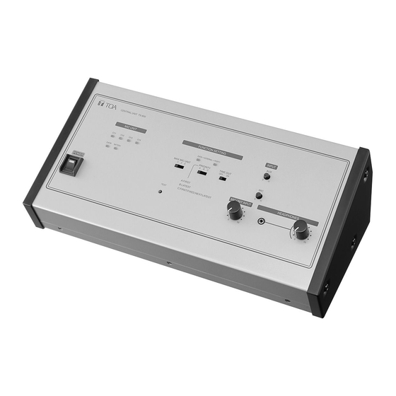
5. NOMENCLATURE AND FUNCTIONS 5.1. Central Unit TS-800 [Top] CENTRAL UNIT TS-800 MIC UNIT FUNCTION SETTING INPUT DATA–EXT–PRIORITY UNIT PRIORITY TIME OUT DATA BATTERY 1 2 4 A B C A: FIRST POWER MIC UNIT INPUT HEADPHONES B: LATEST C: FIRST: FIXED, NEXT: LATEST TEST 9 10 1. - Page 10 10. Simultaneous speaker No. setting switch 12. Mic-off setting switch Used to set the number of Chairman and Automatically turns off Chairman or Delegate unit Delegate units that can be simultaneously microphones 30 seconds after speech is operated. The indications [1], [2], and [4] completed if the user should neglect to turn off represent the number of simultaneously operable the microphone.
- Page 11 [Bottom] DC24V 3A(MAX) EXT CONTROL CHIME REC OUT SHORT INFRARED TRANSMITTER/RECEIVER 16. DC input 23. Infrared transmitter/receiver unit I/O terminals Connect the supplied AC adapter to this terminal. Connect the Infrared Transmitter/Receiver unit or distributor to this terminal. By using the YW-1022 17.
-
Page 12: Chairman Unit Ts-801
5.2. Chairman Unit TS-801 [Top] CHAIRMAN UNIT TS-801 POWER PRIORITY TALK Note No microphone is supplied with the TS-801 Chairman unit. 1. Monitor speaker 6. Talk key Speech input from other Chairman or Delegate When this key is pressed, both the Microphone In- units and the Central unit is output from this Use indicator (3) and the Speech indicator (5) speaker. - Page 13 [Bottom] Remove the cover on the bottom side of the unit to expose its setting switches. Note The label describing the setting switches is shown in the following figure. PRIORITY RESET RESTORE CHIME MUTE NOT USE Not used. UNIT ID 9.
- Page 14 [Right side] 13. Monitor volume control Adjusts the output volume of the monitor speaker and headphone. 14. Headphone jack Connect a headphone to this jack (mini-jack). Connecting the headphone cuts off the output from the monitor speaker. 13 14 Note A headphone jack is located on both the left and right side panels.
-
Page 15: Delegate Unit Ts-802
5.3. Delegate Unit TS-802 [Top] DELEGATE UNIT TS-802 POWER TALK Note No microphone is supplied with the TS-802 Delegate unit. 1. Monitor speaker 5. Speech indicator Speech input from other Chairman or Delegate Remains lit while the microphone is in use (during units and the Central unit is output from this speech). - Page 16 [Bottom] Remove the cover on the bottom side of the unit to expose its setting switches. Note The label describing the setting switches is shown in the following figure. UNIT ID 8. Lithium-ion battery compartment 9. Unit address number setting switch Install only a dedicated BP-900 Lithium-Ion Set the unit address number ([01] –...
- Page 17 [Right side] 10. Monitor volume control Adjusts the output volume of the monitor speaker and headphone. 11. Headphone jack Connect a headphone to this jack (mini-jack). Connecting the headphone cuts off the output from the monitor speaker. Note A headphone jack is located on both the left and right side panels.
-
Page 18: Operation
6. OPERATION 6.1. Initiating Speech Step 1. Press the Talk key on the Chairman or Delegate unit. The Speech indicator and Microphone In-Use indicator light, placing the unit in CHAIRMAN UNIT TS-801 speech mode. No sound is output from the monitor Speech indicator speaker while both indicators are POWER... -
Page 19: Initiating Priority Speech (Ts-801 Only)
6.2. Initiating Priority Speech (TS-801 only) The Chairman unit features the function that allows its speech to take precedence over that of the Delegate unit. The Chairman unit's speech is prior to the AUX and MIC inputs. Step 1. Speak while holding down the Priority Speech key. -
Page 20: Function Settings
7. FUNCTION SETTINGS 7.1. Setting the Maximum Number of Simultaneous Speakers Using the Simultaneous Speaker No. Setting switch on the TS-800 Central FUNCTION SETTING Unit, set the maximum total number of Chairman and Delegate units that can simultaneously initiate speech. DATA–EXTERNAL–PRIORITY UNIT PRIORITY... -
Page 21: Mode C: Priority Fixed For First-Enabled Unit, And Last-In/First-Out Priority For All Subsequent Units
7.2.3. Mode C: priority fixed for first-enabled unit, and last-in/first-out priority for all subsequent units The first-enabled Chairman or Delegate unit is given fixed speech priority until its Talk key is pressed again. All subsequent Talk key-enabled units are given last-in/first-out priority, as in Mode B. •... -
Page 22: System Connection Examples
8. SYSTEM CONNECTION EXAMPLES Central unit TS-800 RS-232C CHIME DC24V 3A(MAX) REC OUT SHORT INFRARED TRANSMITTER/RECEIVER AC adapter Cassette player (supplied with the TS-800) Alternate recording deck Power cord (supplied with the TS-800) Speaker Amplifier Distributor YW-1024 (4-branch distributor) YW-1022 (2-branch distributor) Infrared transmitter/receiver TS-905 or TS-907 For details of the installation and connection of the Infrared Transmitter/Receiver unit,... -
Page 23: Infrared Service Areas
9. INFRARED SERVICE AREAS 9.1. Infrared Transmitter/Receiver • TS-905 150° Ceiling height 2.5 – 4.5 m Radius of communication area • TS-907 90° Ceiling height 5 – 7 m Radius of communication area Model Ceiling height Radius of communication area 2.5 m Approx. -
Page 24: Chairman Unit And Delegate Unit
9.2. Chairman Unit and Delegate Unit 120° 90° 15° 120° 15° CHAIRMAN UNIT TS-801 POWER PRIORITY TALK... -
Page 25: Installation And Connections
10. INSTALLATION AND CONNECTIONS 10.1. Notes on Installation of the Infrared Transmitter/Receiver Unit Installing the Infrared Transmitter/Receiver unit in locations exposed to sunlight or in proximity to such infrared sources as fluorescent lights could result in system failures or the introduction of noise into the system. Avoid installing the Infrared Transmitter/Receiver unit in close proximity to infrared sources, as instructed below: [Avoid direct sunlight] •... -
Page 26: Infrared Transmitter/Receiver Unit Arrangement Examples
10.2. Infrared Transmitter/Receiver Unit Arrangement Examples The area range that an Infrared Transmitter/Receiver unit covers differs depending on the height from the Chairman/Delegate units to the ceiling. (Refer to p. 23.) Arrange the Infrared Transmitter/Receiver units so that all Chairman and Delegate units are included in the service area. -
Page 27: Wiring Between The Infrared Transmitter/Receiver Unit And The Central Unit
10.3. Wiring between the Infrared Transmitter/Receiver Unit and the Central Unit 10.3.1. Notes on wiring Infrared transmitter/receiver Distributor Central unit When two or more Infrared Transmitter/Receiver units receive infrared signals from the Chairman and Delegate units, the signal reception level increases if input signals to each Transmitter/Receiver unit are in phase. - Page 28 [Example 2] Infrared transmitter/receiver Distributor When installing in the same space, • All "L" cables must be identical in length • All "M" cables must be identical in length. Note To facilitate the unification of coaxial cables used in different connections into the same length, it is highly recommended that wiring from the Central unit to the distributor mounted in a ceiling be performed with a single cable.
-
Page 29: Mounting The Infrared Transmitter/Receiver Unit
10.4. Mounting the Infrared Transmitter/Receiver Unit 10.4.1. Ceiling mounting 83.5 mm ø68 ±5 mm Coaxial cable Mounting plate (supplied with the TS-905/-907) Mounting screw Tabs (3 places) Notes • The screws supplied with the TS-905 and TS-907 used for mounting it to the microphone stand. (Refer to the next page.) •... -
Page 30: Mounting On A Microphone Stand
10.4.2. Mounting on a microphone stand Anti-drop screws M3 x 6 (supplied with the TS-905/-907) Infrared transmitter/receiver TS-905/-907 Stand mounting frame (supplied with the TS-905/-907) Coaxial cable Tabs (3 places) Rotate to fix. Mounting plate (supplied with the TS-905/-907) W5/16 – W5/8 thread adapter (supplied with the TS-905*/-907) -
Page 31: Connections Between The Infrared Transmitter/Receiver Unit And The Central Unit
10.5. Connections between the Infrared Transmitter/Receiver Unit and the Central Unit 10.5.1. Connecting Use the coaxial cable with a BNC connector to connect the Infrared Transmitter/Receiver unit to the Central unit. Coaxial cable Central unit TS-800 (rear panel) Live status indicator Infrared transmitter/receiver TS-905/-907 Short circuit indicator... -
Page 32: Coaxial Cable Processing
10.5.2. Coaxial cable processing Coaxial cable Applicable BNC plug 3C-FB and 5C-FB YA-641 (1 piece per package), CC-4900 (10 pieces per package), and CC-4901 (10 pieces per package) 7C-FB YA-642 (1 piece per package) Note: Purchase both the coaxial cable and the required BNC plugs separately. Follow the procedure below to attach the BNC connector to the coaxial cable: Attaching a YA-641 or CC-4901 BNC Plug to the 3C-FB Cable Braided shield... - Page 33 Attaching a CC-4900 BNC Plug to the 3C-FB Cable Braided shield Step 1. Strip the jacket 10 mm from the end of the coaxial cable. 10 mm Tube Step 2. Slip the tube supplied with the BNC plug over the jacket.
- Page 34 Attaching a YA-641 or CC-4901 BNC Plug to the 5C-FB Cable Braided shield Step 1. Strip the jacket 10 mm from the end of the coaxial cable. 10 mm Aluminum cladding Step 2. Unravel the braided shield and turn it back, then peel away the aluminum cladding.
- Page 35 Attaching a CC-4900 BNC Plug to the 5C-FB Cable Braided shield Step 1. Strip the jacket 10 mm from the end of the coaxial cable. 10 mm Aluminum cladding Step 2. Unravel the braided shield and turn it back, then peel away the aluminum cladding.
- Page 36 Attaching a YA-642 BNC Plug to the 7C-FB Cable Step 1. Disassemble the BNC plug as shown in the figure at right. Clamping Open ring Clamping Plug fixture ring Step 2. Strip the jacket 15 mm from the end of the Braided shield coaxial cable.
-
Page 37: Using Wired Microphones And Sound Source Equipment
10.6. Using Wired Microphones and Sound Source Equipment 10.6.1. Wired microphone use Connect a wired microphone to the Central unit's MIC input and adjust its volume with the corresponding MIC input volume control. MIC input volume control Central unit TS-800 Wired microphone (Top panel) CENTRAL UNIT TS-800... -
Page 38: Recording The Conference Contents
10.7. Recording the Conference Contents Connect the recorder's recording input terminal to the Central unit's recording output terminal. If the recorder has its recording level control, adjust it to an appropriate recording level. Note: For operation of the recorder, refer to the instruction manual included with the recorder. Alternate recording deck (Front panel) Headphone... -
Page 39: Chairman And Delegate Unit Installation And Settings
11. CHAIRMAN AND DELEGATE UNIT INSTALLATION AND SETTINGS Step 1. Set the unit address numbers for the Chairman or Delegate unit Chairman and Delegate units to be Bottom side used. To perform this setting, rotate the rotary DIP switches located on the bottom (Inside of the cover) side of the unit with a screwdriver. -
Page 40: Chairman And Delegate Unit Power Supply
12. CHAIRMAN AND DELEGATE UNIT POWER SUPPLY Use either the optional BP-900 Lithium-Ion Battery or the AD-0910 AC Adapter for the power supply of the Chairman and Delegate units. 12.1. BP-900 Lithium-Ion Battery 12.1.1. Inserting the lithium-ion battery Lithium-ion battery BP-900 Arrow Chairman unit TS-801 Delegate unit TS-802... -
Page 41: Recharging
12.1.2. Recharging Use the BC-900 Battery Charger to recharge the BP-900 Lithium-Ion Battery. BP-900 Lithium-Ion Battery Power cord (supplied with the BC-900) Charging status indicator (Red/green) AC adapter (supplied with the BC-900) Power switch Power input terminal BC-900 Battery Charger Step 1. -
Page 42: Ad-0910 Ac Adapter
12.2. AD-0910 AC Adapter Connect the AD-0910 AC Adapter to the DC Inlet located on the left side panel of the Chairman and Delegate units. TS-801/802 DC inlet Power cord AC adapter (supplied with the AD-0910) AD-0910... -
Page 43: Central Unit Rack Mounting
- 8 0 Fiber washers (supplied with the MB-TS900) Rack mounting screws 5 x 12 (supplied with the MB-TS900) Note Supplied 5 x 12 rack mounting screws are designed specifically for TOA's equipment rack. Avoid using them for other rack mounting. -
Page 44: Installation Status Confirmation
14. INSTALLATION STATUS CONFIRMATION Installation status for the Infrared Transmitter/Receiver unit, Chairman unit, and Delegate units can be checked from the Central unit. Switch on the power to the Chairman and Delegate units to confirm their installation status after completing installation and connection. Note None of the unit's functions can be used while in installation status confirmation mode, except Priority Speech initiated from the Chairman unit. -
Page 45: Appendix
15. APPENDIX (Finding the maximum cable length between the Central Unit and the Infrared Transmitter/Receiver Unit) Values calculated here are given only as guidelines, since they can vary depending on ambient building conditions and the Infrared Transmitter/Receiver unit. 15.1. Confirming the Wiring Design To obtain the maximum cable length between the Infrared Transmitter/Receiver unit and the Central unit, calculate the cable length on the following each condition. -
Page 46: Computational Equation
15.2. Computational Equation 15.2.1. Finding the wiring loss Requirement: Total loss 20 dB Cable loss = (Length / 100) x Loss per 100 m Total loss = Cable 1 loss + Cable 2 loss + Cable 3 loss + Distributor 1 loss + Distributor 2 loss Central Unit Distributor 1 Distributor 2... -
Page 47: Design Examples
15.3. Design Examples 15.3.1. Example 1: When installing 4 TS-905 Infrared Transmitter/Receiver units using 4 coaxial cables reaching from the Central unit: Infrared Transmitter/Receiver units Central unit TS-905 1) Finding the maximum cable length using maximum allowable cable losses Assuming that the type of coaxial cable used is RG-59/U, Maximum cable length L = (Coaxial cable loss / its cable loss per 100 m ) = (20 dB / 3.3 dB) x 100 m = 606 m... -
Page 48: Example 2: When Installing 4 Ts-905 Infrared Transmitter/Receiver Units
15.3.2. Example 2: When installing 4 TS-905 Infrared Transmitter/Receiver units using 1 coaxial cable reaching from the Central unit (one 4-branch distributor connected): Condition: Cable length between the Distributor and the TS-905 Infrared Transmitter/Receiver unit is assumed to be 50 meters. Infrared Transmitter/Receiver units Central unit Distributor... - Page 49 2) Finding the maximum cable length using voltage drop The current flowing from the Distributor into each coaxial cable connected to the TS-905 Infrared Transmitter/Receiver unit is 0.1 A, since the number of Infrared Transmitter/Receiver units connected to each coaxial cable is 1. Assuming that RG-59/U coaxial cable is used, the voltage drop between the Distributor and the Infrared Transmitter/Receiver unit is calculated by the following equation: Voltage drop = 16.82 Ω...
-
Page 50: Example 3: When Installing Each 4 Ts-905 Infrared Transmitter/Receiver
15.3.3. Example 3: When installing each 4 TS-905 Infrared Transmitter/Receiver units using 4 coaxial cables reaching from the Central unit (four 4-branch distributors connected): Condition: Cable length between the Distributor and the TS-905 Infrared Transmitter/Receiver unit is assumed to be 50 meters. Infrared Transmitter/Receiver units Distributor TS-905... -
Page 51: Example 4: When Installing 16 Ts-905 Infrared Transmitter/Receiver Units
15.3.4. Example 4: When installing 16 TS-905 Infrared Transmitter/Receiver units using 1 coaxial cable reaching from the Central unit (five 4-branch distributors connected): Condition: Length between the Distributor 2 and the TS-905 Infrared Transmitter/Receiver unit is assumed to be 50 meters, and the length between Distributor 1 and Distributor 2 10 meters. Infrared Transmitter/Receiver units Distributor 2 TS-905... - Page 52 2) Finding the maximum cable length using voltage drop The current flowing from the Distributor 2 into each coaxial cable connected to the TS-905 Infrared Transmitter/Receiver unit is 0.1 A, since the number of Infrared Transmitter/Receiver units connected to each coaxial cable is 1. Assuming that RG-59/U coaxial cable is used, the voltage drop between the Distributor 2 and the Infrared Transmitter/Receiver unit is calculated by the following equation: Voltage drop = 16.82 Ω...
-
Page 53: If A Failure Is Detected
16. IF A FAILURE IS DETECTED 16.1. Chairman Unit TS-801 and Delegate Unit TS-802 Symptom Cause and Points to Check Remedy Cannot turn ON power. (When using the lithium-ion battery) Batteries are not charged as shipped Battery not charged. from the factory. Be sure to fully charge the battery before use. -
Page 54: Central Unit Ts-800
AC outlet. power switch is turned Fuse has blown. The fuse must be replaced. For replacement, consult your TOA dealer. Charging status indicator Is the lithium-ion battery correctly Insert the lithium ion battery fully into its... -
Page 55: Specifications
17. SPECIFICATIONS 17.1. Central Unit TS-800 Power Source 100 – 240V AC, 50/60 Hz (supplied from the accessory AC adapter) Power Consumption 72 W Input MIC: –60 dB*, 600 Ω, unbalanced, phone jack AUX: –20 dB*, 10 kΩ, unbalanced, phone jack Output REC OUT: –20 dB*, 10 kΩ, unbalanced, phone jack, RCA pin jack... -
Page 56: Chairman Unit Ts-801, Delegate Unit Ts-802
17.2. Chairman Unit TS-801, Delegate Unit TS-802 Power Source 7.4 V DC (battery), 9 V DC (AC adapter) (supplied from BP-900 battery or AD-0910 AC adapter) Current Consumption Max. 270 mA Wavelength 870 nm (AM: Brightness modulation) Modulation Method Frequency modulation Carrier Frequency Transmission: Audio channel 1: 7.35 MHz Audio channel 2: 8.10 MHz... -
Page 57: Infrared Transmitter/Receiver Ts-905, Ts-907
17.4. Infrared Transmitter/Receiver TS-905, TS-907 Model No. TS-905 TS-907 Power Source 24 V DC (supplied from the optional TS-800) Current Consumption Max. 150 mA Max. 180 mA Wavelength 870 nm (AM: Brightness modulation) Modulation Method Frequency modulation Carrier Frequency Transmission: Audio channel 1: 7.35 MHz Audio channel 2: 8.10 MHz... -
Page 58: Battery Charger Bc-900
17.6. Battery Charger BC-900 Power Source 100 – 240 V AC, 50/60 Hz Current Consumption Max. 5 A Charging Time Approx. 5 hours Charging Capacity 8 BP-900 batteries (optional) LED Indicator Charging status (Green: Full charge, Red: On charge), Power indicator Operating Temperature 0°C to 40°C Finish... -
Page 59: Distributor Yw-1022 (2-Branch Distributor), Yw-1024 (4-Branch Distributor)
17.8. Distributor YW-1022 (2-branch distributor), YW-1024 (4-branch distributor) Model No. YW-1022 YW-1024 Number of I/O terminals 1 Mixing / 2 Distribution 1 Mixing / 4 Distribution Frequency Range 1.6 – 1,000 MHz (excluding 50 – 70 MHz) Distribution Loss 4.5 dB ±3 dB 8.5 dB ±3 dB (between the Mixing and each (between the Mixing and each... - Page 60 Traceability Information for Europe (EMC directive 2004/108/EC) Manufacturer: Authorized representative: TOA Corporation TOA Electronics Europe GmbH 7-2-1, Minatojima Nakamachi, Chuo-ku, Kobe, Hyogo, Suederstrasse 282, 20537 Hamburg, Japan Germany URL: http://www.toa.jp/ 133-12-911-5H...