Table of Contents
Advertisement
Quick Links
CONFERENCE SYSTEM
Infared Transmitter/
Receiver
Central unit
Thank you for purchasing TOA's Conference System.
Please carefully follow the instructions in this manual to ensure long, trouble-free use of your equipment.
OPERATING INSTRUCTIONS
TS-910 SERIES
E R
O N
P O W
O FF
SU
B
MA
IN
ON
ES
AD
PH
HE
Infrared Delegate unit
Wired Delegate unit
E R
P O W
O N
O FF
SU
B
MA
IN
ON
ES
AD
PH
HE
Infrared Chairman unit
Wired Chairman unit
Advertisement
Table of Contents

Related Manuals for Toa TS-910 s


Summary of Contents for Toa TS-910 s
-
Page 1: Operating Instructions
O FF O FF Infrared Delegate unit Infrared Chairman unit Central unit Wired Delegate unit Wired Chairman unit Thank you for purchasing TOA's Conference System. Please carefully follow the instructions in this manual to ensure long, trouble-free use of your equipment. -
Page 2: Table Of Contents
TABLE OF CONTENTS 1. SAFETY PRECAUTIONS ................4 2. GENERAL DESCRIPTION ................7 3. FEATURES ......................7 4. SYSTEM EQUIPMENT CONFIGURATION ........8 5. NOMENCLATURE AND FUNCTIONS ..........9 5.1. Central Unit TS-910 ....................9 5.2. Infrared Chairman Units TS-901 and TS-801 ............. 11 5.3. - Page 3 11.11. Battery Charger BC-900 .................. 43 11.12. AC Adapter AD-0910 ..................43 11.13. Distributor YW-1022 (2-branch distributor), YW-1024 (4-branch distributor) ... 43 11.14. Rack Mounting Bracket MB-TS900 ..............44 11.15. Half Width Blank Panel MB-15B-BK ..............44 11.16. Rack Joint Bracket MB-15B-J ................44...
-
Page 4: Safety Precautions
1. SAFETY PRECAUTIONS • Before installation or use, be sure to carefully read all the instructions in this section for correct and safe operation. • Be sure to follow all the precautionary instructions in this section, which contain important warnings and/or cautions regarding safety. • After reading, keep this manual handy for future reference. Safety Symbol and Message Conventions Safety symbols and messages described below are used in this manual to prevent bodily injury and property damage which could result from mishandling. Before operating your product, read this manual first and understand the safety symbols and messages so you are thoroughly aware of the potential safety hazards. - Page 5 Applicable to Central unit, Conference unit, Expansion unit, Battery charger, and AC adapter • Should the following irregularity be found during use, immediately switch off the power, disconnect the power supply plug from the AC outlet and contact your nearest TOA dealer. Make no further attempt to operate the unit in this condition as this may cause fire or electric shock.
- Page 6 Applicable to Infrared conference unit • When the unit is not in use for 10 days or more, be sure to take the battery out of the unit because battery leakage may cause a fire, personal injury, or contamination of environment. Applicable to Battery charger • Remove the power supply plug of charger from the AC outlet after charging completion, as doing otherwise may cause a fire. Applicable to Lithium-ion battery • When you discard batteries, please contact the local dealer from whom you bought. Applicable to Central unit, Conference unit, Expansion unit, and Battery charger This is a class A product. In a domestic environment this product may cause radio interference in which case the user may be required to take adequate measures.
-
Page 7: General Description
2. GENERAL DESCRIPTION The TOA TS-910 Series conference system permits both its infrared wireless system unit and wired system unit via CAT-5 LAN cable connections to be used in combination. The wired Chairman and Delegate units (collectively referred to as “Conference units”) are connected to the Central unit via the wired Expansion unit and Bridge unit. -
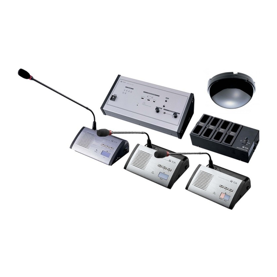
Page 8: System Equipment Configuration
4. SYSTEM EQUIPMENT CONFIGURATION Distributor YW-1024 (4-branch distributor) Infrared Transmitter/ Receiver YW-1022 (2-branch distributor) TS-905 or TS-907 Infrared Transmitter/Receiver Microphone (standard) TS-903 TS-905 or TS-907 Microphone (long) TS-904 Central unit TS-910 PO W OF F PO W OF F Infrared Chairman unit TS-901/801 Infrared Delegate unit TS-902/802 Bridge unit Bridge unit... -
Page 9: Nomenclature And Functions
5. NOMENCLATURE AND FUNCTIONS 5.1. Central Unit TS-910 [Top] 12 13 15 16 1. Power switch 5. External control communication indicator Setting this switch to the ON position causes the Remains lit during communications with a computer Power indicator to light. (PC) or operation panel connected to the rear- mounted External Control terminal. - Page 10 10. Microphone Mix/Cut switch Note (for the base language channel) This switch is factory-preset to the [1] position. MIX: S peech input from the Conference units, and AUX 1 and MIC 1 input signals are 17. Speech priority selector switch output to the base language channel* , and Determines the priority mode when the Talk key of...
-
Page 11: Infrared Chairman Units Ts-901 And Ts-801
5.2. Infrared Chairman Units TS-901 and TS-801 [TS-901 Top] [TS-801 Top] CHAIRMAN UNIT TS -9 0 1 CHAIRMAN UNIT T S - 8 0 1 POWER POWER PRIORITY TALK PRIORITY TALK Note: No microphone is supplied with the TS-901/801. 1. Monitor speaker speech). The indicator flashes when the unit is out Speech signals from other Conference units and of the communications service area. - Page 12 [Bottom] Remove the cover on the bottom side of the unit to expose its setting switches. Note The figure below shows the setting switch labels for both models. [TS-901 setting switch label] [TS-801 setting switch label] RESET RESTORE PRIORITY RESET RESTORE PRIORITY CHIME MUTE...
- Page 13 [Right side] 16. Monitor volume control Adjusts the output volume of the monitor speaker and right-side headphone output. 17. Monitor selector switch (TS-901 only) Selects either Base Language or Translation Language for the source to be output to the monitor speaker and headphones. 18. Headphone jack Connect headphones to this jack (mini-jack). Connecting the headphone cuts off the output from the monitor speaker.
-
Page 14: Wired Chairman Units Ts-911 And Ts-811
5.3. Wired Chairman Units TS-911 and TS-811 [TS-911 Top] [TS-811 Top] PUSH PUSH Note: No microphone is supplied with the TS-911/811. 1. Monitor speaker 7. Priority speech key Speech signals from other Conference units and Gives speaking priority to the current speaker. other audio signals from the Central unit are output When this key is used for speech, no other delegate from this speaker. - Page 15 [Bottom] Remove the cover on the bottom side of the unit to expose its setting switches. Note The figure below shows the setting switch labels for both models. [TS-911 setting switch label] [TS-811 setting switch label] RESET RESTORE PRIORITY RESET RESTORE PRIORITY CHIME MUTE...
- Page 16 [Right side] 14. Monitor volume control Adjusts the output volume of the monitor speaker and right-side headphone output. 15. Headphone jack Connect headphones to this jack (mini-jack). Connecting the headphone cuts off the output from the monitor speaker. (Refer to the table below.) Model Output signal 14 15 TS-911 Base language or Translation language Note: Switchable by the Monitor selector switch (16).
-
Page 17: Infrared Delegate Units Ts-902 And Ts-802
[Rear] 18. Communication cable connection terminal Connects to the TS-919B4 or TS-919B1 Bridge unit with a CAT-5 LAN cable. 5.4. Infrared Delegate Units TS-902 and TS-802 [TS-902 Top] [TS-802 Top] DELEGATE UNIT TS -9 0 2 DELEGATE UNIT T S - 8 02 POWER POWER TALK... - Page 18 signal access to this part of the unit, as this would Use indicator (3) and the Speech indicator (6) light, prevent the unit from transmitting or receiving its and the microphone turns on. Pressing this key required infrared signal. again turns off both indicators and the microphone. 5.
- Page 19 [Right side] 11. Monitor volume control Adjusts the output volume of the monitor speaker and right-side headphone output. 12. Monitor selector switch (TS-902 only) Selects either Base Language or Translation Language for the source to be output to the monitor speaker and headphone. 13. Headphone jack Connect headphones to this jack (mini-jack). Connecting the headphone cuts off the output from the monitor speaker.
-
Page 20: Wired Delegate Units Ts-912 And Ts-812
5.5. Wired Delegate Units TS-912 and TS-812 [TS-912 Top] [TS-812 Top] PUSH PUSH Note: No microphone is supplied with the TS-912/812. 1. Monitor speaker 4. Voting keys (TS-912 only) Speech signals from other Conference units and Use these keys to start, end, and cast voting. The other audio signals from the Central unit are output voting status indicator is provided on each key. - Page 21 [Bottom] Remove the cover on the bottom side of the unit to expose its setting switches. Note The figure below shows the setting switch label. NOT USE UNIT ID 8. Unit address number setting switch Set the unit address number (001 – 192), taking Set a numeral for the ones place and tens place.
-
Page 22: Expansion Unit Ts-918
[Left side] 12. Headphone volume control Adjusts the output volume of the left-side headphone output. 10 12 5.6. Expansion Unit TS-918 [Front] 1. Power indicator 2. Connection status indicators Lights when connecting the supplied AC adapter to The corresponding LINE indicator lights when the the DC inlet on the rear panel. -
Page 23: Bridge Unit (4-Conference Unit Connection Type) Ts-919B4
5.7. Bridge Unit (4-Conference unit connection type) TS-919B4 [Front] 1. Connection status indicators The corresponding LINE indicator lights when the Wired Conference unit is connected to the Conference unit connection terminal on BRIDGE UNIT TS-919B4 the bottom side and power is supplied to it. EXPANSION BRIDGE 5.8. -
Page 24: Function Settings
6. FUNCTION SETTINGS 6.1. Setting the Maximum Number of Simultaneous Speakers Using the Simultaneous Speaker No. Setting switch on the TS- 910 Central Unit, set the maximum total number of Conference units that can simultaneously initiate speech. Set the switch to [1], [2], [3], or [4] depending on the type of the conference. -
Page 25: Mic-Off Function
6.2.3. Mode C: Priority fixed for first-enabled unit, and last-in/first-out priority for all subsequent units The first-enabled Conference unit is given fixed speech priority until its Talk key is pressed again. All subsequent Talk key-pressed units are given last-in/first-out priority, as in Mode B. • Example showing the number of simultaneous speakers set to [2]. -
Page 26: Microphone Mix/Cut Switch Settings
7. MICROPHONE MIX/CUT SWITCH SETTINGS Whether to output voice signals from Conference units to the base or translation language channel can be determined by setting the Microphone Mix/ Cut switch on the TS-910 Central unit. Outputs for individual inputs (MIC 1 – 2, and AUX 1 –... -
Page 27: Operation
8. OPERATION 8.1. Initiating Speech Step 1. Press the Talk key on the Conference unit. The Speech indicator and Microphone In-Use indicator light, placing the unit in speech mode. CHAIRMAN UNIT TS-901 No sound is output from the monitor Speech indicator speaker while both... -
Page 28: Initiating Priority Speech (Ts-901, Ts-801, Ts-911, And Ts-811 Only)
8.2. Initiating Priority Speech (TS-901, TS-801, TS-911, and TS-811 only) The Chairman unit features the function that allows its speech to take precedence over that of the Delegate unit. The Chairman unit's speech is prior to the AUX 1, AUX 2, AUX 3, MIC 1, and MIC 2 inputs. The priority speech method can be determined by the Priority speech key operation setting switch built in the Chairman unit’s bottom. - Page 29 8.2.2. When the Priority Speech key is set to ALT type Step 1. Press the Priority Speech key. Both the Speech indicator and the Microphone In-Use indicator light, placing the unit in priority speech mode. No sound is output from the monitor speaker while both indicators are continuously lit.
-
Page 30: Voting (Ts-901, Ts-911, Ts-902, And Ts-912 Only)
8.3. Voting (TS-901, TS-911, TS-902, and TS-912 only) Voting can be started and terminated from the Central unit or the Chairman unit. To perform this operation from the Chairman unit, set the Voting activation setting switch to ON as shown in the figure. -
Page 31: If Acoustic Feedback Occurs
Step 3. Terminate voting. (For the Chairman unit) Again hold down the Voting Start/End button on the Central unit for 1 second or more or alternatively the Chairman unit’s Talk key. Voting operations from the Conference units are confirmed PRIORITY TALK and Voting Status indicators [1] through [3] go out. The result Hold down this key of computed votes is displayed on Voting Result displays [1] for 1 second or more. -
Page 32: Using An External Graphic Equalizer
9.1.2. Using in manual operation mode (MANUAL mode) If acoustic feedback does not stop even using the FBS function in automatic operation mode, follow the procedure below to search the frequency that caused feedback, then suppress the feedback. Step 1. Set the Feedback suppressor switch to the MANUAL position. -
Page 33: If A Failure Is Detected
10. IF A FAILURE IS DETECTED 10.1. Infrared Chairman Unit TS-901/801 and Infrared Delegate Unit TS-902/802 Symptom Cause and Points to Check Remedy Cannot turn ON power. (When using the lithium-ion battery) Batteries are not charged as shipped Battery not charged. from the factory. -
Page 34: Wired Chairman Unit Ts-911/811 And Wired Delegate Unit Ts-912/812
Symptom Cause and Points to Check Remedy Indicator on the Mic-Off function set to ON. Disable the Mic-Off function if a long microphone goes out pause is made during speech. during speech. Microphone indicator Battery voltage has dropped below a Replace the battery with a fully charged flashes. -
Page 35: Central Unit Ts-910
Fuse has blown. The fuse must be replaced. switch is turned ON. For replacement, consult your TOA dealer. Charging status Lithium-ion battery not correctly inserted Insert the lithium ion battery fully into its indicator (red) does into its receptacle. -
Page 36: Specifications
11. SPECIFICATIONS 11.1. Central Unit TS-910 Power Source 100 – 240 V AC, 50/60 Hz (use of the supplied AC adapter) Power Consumption 72 W Current Consumption Max. 3 A DC (when 24 V DC is supplied from the supplied AC adapter) Current Frequency Reception: Audio channel 1:... -
Page 37: Infrared Chairman Unit Ts-901, Infrared Delegate Unit Ts-902
• Accessory AC adapter* (DC cord: 1.8 m or 5.91 ft, Detachable AC cord: 2 m or 6.56 ft) ..1 * N ot supplied with the TS-918 (KR). For the usable power supply cord and AC adapter, consult your nearest TOA dealer. 11.2. Infrared Chairman Unit TS-901, Infrared Delegate Unit TS-902 Model No. TS-901 TS-902 Power Source 7.4 V DC (battery), 9 V DC (AC adapter) (supplied from BP-900 battery or AD-0910 AC adapter) Current Consumption Max. -
Page 38: Infrared Chairman Unit Ts-801, Infrared Delegate Unit Ts-802
11.3. Infrared Chairman Unit TS-801, Infrared Delegate Unit TS-802 Model No. TS-801 TS-802 Power Source 7.4 V DC (battery), 9 V DC (AC adapter) (supplied from BP-900 battery or AD-0910 AC adapter) Current Consumption Max. 270 mA Wavelength 870 nm (AM: Brightness modulation) Modulation Method Frequency modulation Carrier Frequency Transmission: Audio channel 1: 7.35 MHz... -
Page 39: Wired Chairman Unit Ts-911, Wired Delegate Unit Ts-912
11.4. Wired Chairman Unit TS-911, Wired Delegate Unit TS-912 Model No. TS-911 TS-912 Power Source 24 V DC (supplied from the optional TS-918 Expansion unit) Current Consumption Max. 60 mA Modulation Method Frequency modulation Carrier Frequency Transmission: Audio channel 1 7.35 MHz Audio channel 2 8.10 MHz Audio channel 3 8.55 MHz... -
Page 40: Wired Chairman Unit Ts-811, Wired Delegate Unit Ts-812
11.5. Wired Chairman Unit TS-811, Wired Delegate Unit TS-812 Model No. TS-811 TS-812 Power Source 24 V DC (supplied from the optional TS-918 Expansion unit) Current Consumption Max. 60 mA Modulation Method Frequency modulation Carrier Frequency Transmission: Audio channel 1: 7.35 MHz Audio channel 2: 8.10 MHz Audio channel 3: 8.55 MHz Audio channel 4: 9.15 MHz Control channel: 6.45 MHz Reception: Audio channel: 1.95 MHz... -
Page 41: Infrared Transmitter/Receiver Ts-905, Ts-907
11.7. Infrared Transmitter/Receiver TS-905, TS-907 Model No. TS-905 TS-907 Power Source 24 V DC (supplied from the optional TS-910) Current Consumption Max. 150 mA Max. 180 mA Wavelength 870 nm (AM: Brightness modulation) Modulation Method Frequency modulation Carrier Frequency Transmission: Audio channel 1: 7.35 MHz Audio channel 2: 8.10 MHz Audio channel 3: 8.55 MHz Audio channel 4:... -
Page 42: Bridge Unit Ts-919B1, Ts-919B4
• Accessories AC adapter* (DC cord: 1.8 m or 5.91 ft, Detachable AC cord: 2 m or 6.56 ft ) ..1 BNC plug-to BNC plug cord (50 cm or 1.64 ft) ............1 * N ot supplied with the TS-918 (KR). For the usable power supply cord and AC adapter, consult your nearest TOA dealer. 11.9. Bridge Unit TS-919B1, TS-919B4 Model No. TS-919B1 TS-919B4 Power Source 24 V DC (supplied from the optional TS-918 Expansion Unit) Current Consumption Max. -
Page 43: Battery Charger Bc-900
11.11. Battery Charger BC-900 Power Source 100 – 240 V AC, 50/60 Hz (use of the supplied AC adapter) Current Consumption Max. 5 A DC Charging Time Approx. 5 hours Charging Capacity 8 BP-900 batteries (optional) LED Indicator Charging status (Green: Full charge, Red: On charge), Power indicator Operating Temperature 0 to 40 ºC (32 to 104 ºF) Operating Humidity 90 %RH or less (no condensation) -
Page 44: Rack Mounting Bracket Mb-Ts900
Tapping screw 3 x 8 ........6 Machine screw M3 x 12 ......6 Machine screw M3 x 6 ....... 4 Traceability Information for Europe Manufacturer: Authorized representative: TOA Corporation TOA Electronics Europe GmbH 7-2-1, Minatojima-Nakamachi, Chuo-ku, Kobe, Hyogo, Suederstrasse 282, 20537 Hamburg, Japan Germany URL: http://www.toa.jp/ 133-07-00007-03...