Table of Contents
Advertisement
Quick Links
Advertisement
Table of Contents

Related Manuals for Toa TS-800


Summary of Contents for Toa TS-800
- Page 1 TS-800/900 Infrared Wireless Conference System COOKBOOK...
-
Page 2: General Description
• The TS-800 Series represents a cordless version of the TS-700 Series. Thus, its functions are almost identical with those of the TS-700. - Page 3 The number of the Chairman and Delegate units can be varied according to fit the number of participants. (TS-800 Series: up to 64 units; TS-900 Series: up to 96 units) Up to 16 Transmitter/Receiver units (when using TS-905 units only) and up to 12...
-
Page 4: System Equipment Configuration
YW-1022 (2-branch distributor) Note: Connectable up to 16 units (TS-905) and up to 12units (TS-907) Infrared transmitter/receiver TS-905/TS-907 AC adapter Power cord Central unit (supplied with the TS-800) (supplied with the TS-800) TS-800 Microphone (standard) TS-903 Microphone (long) TS-904 Chairman unit TS-801... - Page 5 SYSTEM EQUIPMENT CONFIGURATION TS-800 SERIES SYSTEM EQUIPMENT CONFIGURATION Central Unit: TS-800 • The unit is used to select the speech system as well as set the number of participants allowed to talk. • The unit can handle up to 64 conference units (TS-801, TS-802).
- Page 6 SYSTEM EQUIPMENT CONFIGURATION TS-900 SERIES SYSTEM EQUIPMENT CONFIGURATION Distributor YW-1024 (4-branch distributor) Infrared transmitter/receiver TS-905/TS-907 YW-1022 (2-branch distributor) Note: Connectable up to 16 units (TS-905) and up to 12units (TS-907) Infrared transmitter/receiver TS-905/TS-907 AC adapter Power cord Central unit (supplied with the TS-900) (supplied with the TS-900) TS-900 Microphone (standard) TS-903...
- Page 7 SYSTEM EQUIPMENT CONFIGURATION TS-900 SERIES SYSTEM EQUIPMENT CONFIGURATION Central Unit: TS-900 • The unit is used to select the speech system and set the number of participants allowed to talk. • The unit features the threefold vote function. • The unit is equipped with two channels (MAIN, SUB) for speech output to conference units.
- Page 8 SYSTEM EQUIPMENT CONFIGURATION TS-800/TS-900 SERIES Accessories (for both TS-900 Series and TS-800 Series) Dedicated battery charger: BC-900 • A dedicated battery charger for use with the BP-900 Standard microphone: TS-903 lithium-ion battery. • A microphone designed for exclusive • Capable of simultaneously use with conference units.
-
Page 9: System Connection Examples
Central unit TS-800 DC24V 3A(MAX) RS-232C CHIME REC OUT SHORT INFRARED TRANSMITTER/RECEIVER AC adapter Cassette player (supplied with the TS-800) Power cord Alternate recording deck (supplied with the TS-800) Speaker Amplifier Distributor YW-1024 (4-branch distributor) YW-1022 (2-branch distributor) Infrared transmitter/receiver... - Page 10 SYSTEM CONNECTION EXAMPLE TS-900 SYSTEM CONNECTION EXAMPLES For the translation For the base language channel language channel For the base language and translation language channels Central unit TS-900 MIX CUT DC24V 3A(MAX) AUX3 AUX2 MIC2 AUX1 MIC1 EXT CONTROL LEVEL CHIME AUX3 LINE OUT...
- Page 11 SYSTEM CONNECTION EXAMPLE TS-900 SERIES System connection example for bilingual conferencing (TS-900 Series) The 2-channel monitor function enables to conduct a simple bilingual conference. (Refer to the connections shown in the chart) Interpreter’s booth (1) Interpreter’s booth (2) English Japanese Japanese English [ X ]...
- Page 12 SYSTEM CONNECTION EXAMPLE TS-900 SERIES Sound Input/Output Diagram (TS-900 Series) Main Sound Sub Sound Line Rec. Out Infrared MIC1 AUX1 MIC2 AUX2 AUX3 Aux3 Cut Sub Cut Main Cut Link...
-
Page 13: Infrared Transmitter/Receiver
INFRARED SERVICE AREAS TS-800/TS-900 Infrared Transmitter/Receiver [Side view] TS-905 TS-907 [Optimal Coverage Areas] [Top view] Ceiling Radius of Model No. height coverage area (A) 2.5m Approx. 7.0m Infrared transmitter/ 3.0m receiver TS-905 3.5m Approx. 6.5m 4.0m 4.5m 5.0m 5.5m TS-907 6.0m... -
Page 14: Chairman Unit And Delegate Unit
INFRARED SERVICE AREAS TS-800/TS-900 Chairman Unit and Delegate Unit Note: The conference unit sends and receives signals only in the front direction. The conference unit thus cannot communicate with Transmitter/Receiver units that are placed behind it. It is important to set up the Transmitter/Receiver in front of terminals to be used. - Page 15 As with the TOA Infrared Conference System, these systems also use infrared light. Thus, if used in the same location, they could interfere with each other. In some cases, it may be the TOA system that fails; in other cases, it may be the other system that becomes inoperable.
- Page 16 CAUTIONS IN INSTALLING TS-800/900 SERIES Cautions in installing the Transmitter/Receiver unit 1. Install the Transmitter/Receiver unit away from windows. Install the unit 2 – 3 meters away from the nearest window, so that the effect of sunlight is minimized. Sunlight 2 –...
- Page 17 CAUTIONS IN INSTALLING TS-800/900 SERIES Cautions in installing the Transmitter/Receiver unit 4. Arrange the Transmitter/Receiver unit in such a way that individual conference units can communicate with more than one Transmitter/Receiver unit. As shown in a drawing, when a speaker in the front row talks while standing up, the infrared reception could be interrupted.
- Page 18 CAUTIONS IN INSTALLING TS-800/900 SERIES Cautions in installing the conference unit Make sure that the infrared signal receiver of the unit is not exposed to direct sunlight. If direct sunlight hits the infrared signal receiver, the reception may be interrupted.
- Page 19 TRANSMITTER/RECEIVER UNIT TS-800/900 SERIES Transmitter/Receiver unit arrangement example The maximum straight-line distance permissible for communication between the Transmitter/Receiver unit and the conference unit is 7 meters. Thus, the area range the Transmitter/Receiver unit Area for installing the Chairman/Delegate units can cover varies depending on the height from the conference unit to the ceiling.
- Page 20 TRANSMITTER/RECEIVER UNIT TS-800/900 SERIES Transmitter/Receiver unit arrangements according to the seating style When the same number of Transmitter/Receiver units is installed in rooms with the same size, the arrangement of the units varies depending on the seat layout. The drawings below represent ideal Transmitter/Receiver unit arrangements for roundtable seating and parliamentary seating styles.
- Page 21 TRANSMITTER/RECEIVER UNIT TS-800/900 SERIES Transmitter/Receiver unit arrangements according to the room size The drawings below show examples of the Transmitter/Receiver unit placement for different room sizes for both roundtable and parliamentary seating styles. Roundtable seating 6000 10000 15000 TS-802 TS-802...
- Page 22 TRANSMITTER/RECEIVER UNIT TS-800/900 SERIES Wiring between the Transmitter/Receiver unit and the Central unit 1. Note on wiring When two or more Transmitter/Receiver units receive infrared signals from the conference unit, the signal reception level increases if input signals to each Transmitter/Receiver unit are in phase.
- Page 23 TRANSMITTER/RECEIVER UNIT TS-800/900 SERIES Wiring between the Transmitter/Receiver unit and the Central unit [Example 2] Infrared transmitter/receiver Distributor When installing in the same space. • All "L" cables must be identical in length. • All "M" cables must be identical in length.
- Page 24 TRANSMITTER/RECEIVER UNIT TS-800/900 SERIES Wiring Design Exsamples (Finding the maximum cable length between the Central Unit and the Infrared Transmitter/Receiver Unit) Values calculated here are given only as guidelines, since they can vary depending on ambient building conditions and the Infrared Transmitter/Receiver unit.
-
Page 25: Computational Equation
TRANSMITTER/RECEIVER UNIT TS-800/900 SERIES Wiring Design Exsamples Computational Equation Finding the wireing loss Requirement: Total loss & 20 dB Cable loss = (Length/100) Loss per 100 m Total loss = Cable 1 loss + Cable 2 loss + Cable 3 loss + Distributor 1 loss + Distributor 2 loss... -
Page 26: Design Examples
TRANSMITTER/RECEIVER UNIT TS-800/900 SERIES Wiring Design Exsamples Design Examples Example 1: When installing 4 TS-905 Infrared Transmitter/Receiver units using 4 coaxial cables reaching from the Central unit: Central unit Transmitter/Receiver units 1) Finding the maximum cable length using maximum allowable cable losses... - Page 27 TRANSMITTER/RECEIVER UNIT TS-800/900 SERIES Wiring Design Exsamples Example 2: When installing 4 TS-905 Infrared Transmitter/Receiver units using 4 coaxial cables reaching from the Central unit (one 4-branch distributor connected): Condition: Cable length between the Distributor and the Infrared Transmitter/Receiver unit is assumed to be 50 meters.
- Page 28 TRANSMITTER/RECEIVER UNIT TS-800/900 SERIES Wiring Design Exsamples 2) Finding the maximum cable length using voltage drop The current flowing from the Distributor into each coaxial cable connected to the TS-905 Infrared Transmitter/Receiver unit is 0.1 A, since the number of Infrared Transmitter/Receiver units connected to each coaxial cable is 1.
- Page 29 TRANSMITTER/RECEIVER UNIT TS-800/900 SERIES Wiring Design Exsamples Example 3: When installing 4 TS-905 Infrared Transmitter/Receiver units using 4 coaxial cables reaching from the Central unit (four 4-branch distributors connected): Condition: Cable length between the Distributor and the TS-905 Infrared Transmitter/Receiver unit is assumed to be 50 meters.
- Page 30 TRANSMITTER/RECEIVER UNIT TS-800/900 SERIES Wiring Design Exsamples Example 4: When installing 16 TS-905 Infrared Transmitter/Receiver units using 1 coaxial cable reaching from the Central unit (five 4-branch distributors connected): Condition: Length between the Distributor 2 and the TS-905 Infrared Transmitter/Receiver unit is assumed to be 50 meters, and the length between Distributor 1 and Distributor 2 10 meters.
- Page 31 TRANSMITTER/RECEIVER UNIT TS-800/900 SERIES Wiring Design Exsamples 2) Finding the maximum cable length using voltage drop The current flowing from the Distributor 2 into each coaxial cable connected to an Infrared Transmitter/Receiver unit is 0.1 A, since the number of Infrared Transmitter/Receiver units connected to each coaxial cable is 1.
- Page 32 TRANSMITTER/RECEIVER UNIT TS-800/900 SERIES Notes on installation (summary) Notes on installation (summary) • The coverage area of infrared communication varies depending on the type of the Transmitter/Receiver unit used and ceiling height. (see page 5-1) • The TS-905 works for ceiling heights of more than 2.5 meters and less than 5 meters, while the TS-907 works for heights of between 5.0 meters and 7.0 meters.
- Page 33 Note: This function is also available on the TS-800 Series. In the case of the TS-800, switch on the power while holding down the TEST button. Indication of the numbers of installed units is not...
- Page 34 USEFUL-TO-KNOW FUNCTIONS TS-800/900 SERIES Useful-to-know functions (2) Monitor-dedicated unit A conference unit can be used exclusively as a monitor by assigning the ID number "00" to the unit. (In this situation, the unit cannot be used for speech) Because the monitor-dedicated unit is free from the restrictions on the maximum number of connectable conference units (96 units for the 900 Series and 64 for the 800 Series), it is possible to use any number of monitor-dedicated units.
- Page 35 COMPARISON OF FEATURES TS-800/900 SERIES Comparison of features between the TS-800/900 and TS-700 series TS-800/900 TS-700 Number of simultaneous speaker units 1/2/4 1/2/4/6 Auto Mic-off time setting Fixed at 30 seconds 20 seconds/40 seconds Speech system First-in-first-out/Last-in-first-out/ Last-in-first-out after 2nd unit First-in-firs out”...
-
Page 36: Specifications
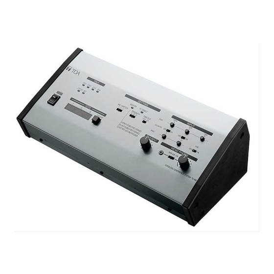
TS-800 TS-800 CENTRAL UNIT The TS-800 is a Central unit of the Infrared Conference system. Since the system is cordless, it can be easily installed and removed based on a free layout. Connecting the TS-800 to the Transmitter/Receiver units permits control of the conference units. - Page 37 SPECIFICATIONS TS-801 TS-801 CHAIRMAN UNIT The TS-801 is a Chairman unit of the Infrared Conference system. Since the system is cordless, it can be easily installed and removed. The Chairman unit features a priority speech key which allows it to take precedence over the TS-802 Delegate units (optional) when speaking.
- Page 38 SPECIFICATIONS TS-802 TS-802 DELEGATE UNIT The TS-802 is a Delegate unit of the Infrared Conference system. Since the system is cordless, it can be easily installed and removed. It can be operated on either the AD-0910 AC adapter (optional) or the BP-900 lithium-ion battery (optional). It is equipped with a remaining battery indicator.
- Page 39 SPECIFICATIONS TS-900 TS-900 CENTRAL UNIT The TS-900 is a Central unit of the Infrared Conference system. Since the system is cordless, it can be easily installed and removed based on a free layout. Connecting the TS-900 to the Transmitter/Receiver units permits control of the conference units. It features control function from a PC (The control software is not attached.), installation confirmation function that confirms the connection status for the Transmitter/Receiver units and installation status for the conference units, and voting function that computes and displays the voting result.
- Page 40 SPECIFICATIONS TS-901 TS-901 CHAIRMAN UNIT The TS-901 is a Chairman unit of the Infrared Conference system. Since the system is cordless, it can be easily installed and removed. The Chairman unit features a priority speech key which allows it to take precedence over the TS-902 Delegate units (optional) when speaking.
- Page 41 SPECIFICATIONS TS-902 TS-902 DELEGATE UNIT The TS-902 is a Delegate unit of the Infrared Conference system. Since the system is cordless, it can be easily installed and removed. It can be operated on either the AD-0910 AC adapter (optional) or the BP-900 lithium-ion battery (optional). It is equipped with a remaining battery indicator.
- Page 42 SPECIFICATIONS TS-903 TS-903 MICROPHONE The TS-903 is a designed microphone for exclusive use with the conference units of the Infrared Conference system. Ring type In-Use lamp located at the microphone head permits displaying the operation status of the conference units Type Electret condenser microphone Directivity...
- Page 43 SPECIFICATIONS TS-904 TS-904 MICROPHONE The TS-904is a designed microphone for exclusive use with the conference units of the Infrared Conference system. Ring type In-Use lamp located at the microphone head permits displaying the operation status of the conference units Type Electret condenser microphone Directivity Unidirectional...
-
Page 44: Mounting Bracket
TS-905 permits transmit and receive with the Central unit. It can be mounted not only to the ceiling and wall but on the microphone stand. Power Source 24 V DC (supplied from the optional TS-900 or TS-800) Current Consumption Max. 100 mA... - Page 45 TS-907 permits transmit and receive with the Central unit. It can be mounted not only to the ceiling and wall but on the microphone stand. Power Source 24 V DC (supplied from the optional TS-900 or TS-800) Current Consumption Max. 180 mA...
- Page 46 SPECIFICATIONS YW-1022 YW-1022 DISTRIBUTOR The YW-1022 is a distributor that can work in the frequency range of 1.6 to 1,000 MHz (except 50 to 70 MHz). Power passing type permits easy power supply. Frequency Range 1.6 – 1,000 MHz (excluding 50 – 70 MHz) Distribution Loss 4.5 dB 3 dB (between the Mixing and each Distribution terminals) Input/Output Impedance...
- Page 47 SPECIFICATIONS YW-1024 YW-1024 DISTRIBUTOR The YW-1024 is a distributor that can work in the frequency range of 1.6 to 1,000 MHz (except 50 to 70 MHz). Power passing type permits easy power supply. Frequency Range 1.6 – 1,000 MHz (excluding 50 – 70 MHz) Distribution Loss 8.5 dB 3 dB (between the Mixing and each Distribution terminals) Input/Output Impedance...
- Page 48 SPECIFICATIONS AD-0910 AD-0910 AC ADAPTER The AD-0910 is an AC adapter to operate the Chairman units TS-801 and TS-901, and the Delegate units TS-802 and TS-902 on AC. Power Source 100 – 240 V AC, 50/60 Hz Output 9 V DC, 1 A Ripple Voltage 100 mV (p-p) Power Consumption...
- Page 49 SPECIFICATIONS BC-900 BC-900 BATTERY CHARGER The BC-900 is a dedicated battery charger for the BP-900 (optional) used in the Chairman Units, and Delegate Units. It permits up to 8 batteries to be simultaneously charged within up to 5 hours. Power Source 100 –...
-
Page 50: Bp-900 Lithium-Ion Battery
SPECIFICATIONS BP-900 BP-900 LITHIUM-ION BATTERY The BP-900 is a rechargeable lithium-ion battery designed for exclusive use with the conference units TS-801, TS-802, TS-901 and TS-902. Nominal Voltage 7.4 V DC Nominal Capacity 1700 mAh Operating Temperature 0 C to +40 C Dimensions 71.6 (W) 20.4 (H) 37.6 (D) mm Weight... - Page 51 MB-TS900 MB-TS900 RACK MOUNTING BRACKET The MB-TS900 Rack Mounting Bracket is designed for exclusive use with the Central units TS-800 and TS-900 of the TOA Infrared Conference Systems. The MB-TS900 is a 4-units size that can be mounted in an EIA Standard equipment rack.
- Page 52 INTERNAL CONTROL FUNCTIONS TS-800/900 SERIES Functions that can be performed without using external equipment (PC) Basic Operations When the TALK key of the Chairman and Delegate units (hereinafter referred to as "the conference . (similar to the TS-700's) unit") is pressed, the Speech indicator (located on the control panel of the conference unit and at the tip of the standard/long microphone) lights up and the microphone turns on, placing the unit in speech mode.
- Page 53 EXTERNAL CONTROL FUNCTIONS TS-800/900 SERIES Functions that can be Enabled by External Equipment The system can be remotely controlled by connecting external equipment, such as a personal computer or operation desk to the Center Unit. Connecting external equipment enables the following functions to be performed.