Table of Contents
Advertisement
Quick Links
Advertisement
Table of Contents

Related Manuals for Toa TS-920 Series


Summary of Contents for Toa TS-920 Series
- Page 1 INSTRUCTION MANUAL CONFERENCE SYSTEM TS-920 SERIES Infrared transmitter/receiver Infrared delegate unit Infrared chairman unit Central unit Thank you for purchasing TOA's Conference system. Please carefully follow the instructions in this manual to ensure long, trouble-free use of your equipment.
-
Page 2: Table Of Contents
TABLE OF CONTENTS 1. SAFETY PRECAUTIONS ................4 2. GENERAL DESCRIPTION ................7 3. FEATURES ......................7 4. SYSTEM EQUIPMENT CONFIGURATION ........8 5. NOMENCLATURE AND FUNCTIONS ..........9 5.1. Central Unit TS-920RC ..................9 5.2. Infrared Chairman Units TS-921 and TS-821 ............ 14 5.3. - Page 3 16.2. Initiating Priority Speech (TS-921 and TS-821 only) ........45 16.3. Voting (TS-921 and TS-922 only) ..............47 16.4. Using the Recording Function ................48 17. IF ACOUSTIC FEEDBACK OCCURS ..........54 17.1. Using the Built-in FBS Function ................ 54 17.2.
-
Page 4: Safety Precautions
1. SAFETY PRECAUTIONS • Before installation or use, be sure to carefully read all the instructions in this section for correct and safe operation. • Be sure to follow all the precautionary instructions in this section, which contain important warnings and/or cautions regarding safety. - Page 5 • Should the following irregularity be found during use, immediately switch off the power, disconnect the power supply plug from the AC outlet and contact your nearest TOA dealer. Make no further attempt to operate the unit in this condition as this may cause fire or electric shock.
- Page 6 Applicable to Central unit, Conference unit, Battery charger, and AC adapter • Never plug in nor remove the power supply plug with wet hands, as doing so may cause electric shock. • When unplugging the power supply cord, be sure to grasp the power supply plug; never pull on the cord itself. Operating the unit with a damaged power supply cord may cause a fire or electric shock.
-
Page 7: General Description
2. GENERAL DESCRIPTION The TOA TS-920 Series conference system employs its infrared wireless system unit. The Infrared chairman and Delegate units (collectively referred to as "Conference units") provide wireless communication via the Infrared transmitter/receiver unit connected to the Central unit. Since wiring to the individual Conference units is not required, they can be easily installed in freely versatile configurations. -
Page 8: System Equipment Configuration
4. SYSTEM EQUIPMENT CONFIGURATION Distributor YW-1024 (4-branch distributor) Infrared Transmitter/ Receiver YW-1022 (2-branch distributor) TS-905 or TS-907 Infrared Transmitter/Receiver Microphone (standard) TS-923 TS-905 or TS-907 Microphone (long) TS-924 Central unit TS-920RC Infrared Chairman unit TS-921/821 Infrared Delegate unit TS-922/822 Lithium-Ion Battery BP-900A (for TS-921/922/821/822) AC Adapter AD-0910RC (for TS-921/922/821/822) -
Page 9: Nomenclature And Functions
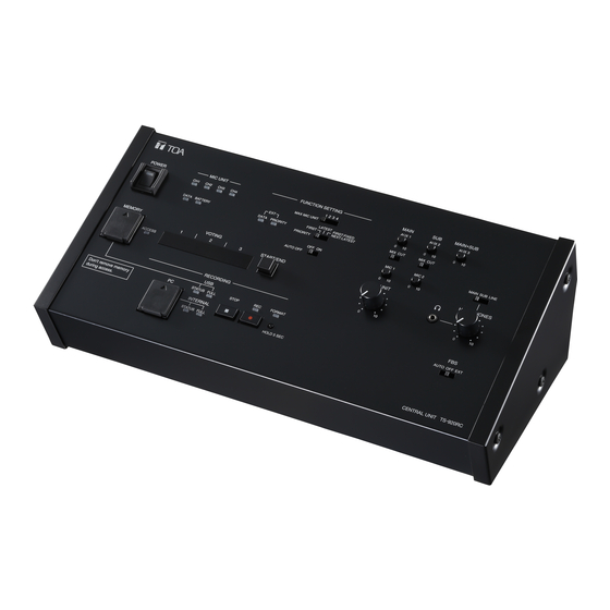
5. NOMENCLATURE AND FUNCTIONS 5.1. Central Unit TS-920RC [Top] 13 14 Internal of rubber cap 25 26 33 34 Internal of rubber cap 1. Power switch [POWER] 5. Battery indicator [BATTERY] Setting this switch to the ON position causes the Flashes when the lithium-ion battery of the Infrared Power indicator to light. - Page 10 8. Number of open microphones setting switch 14. Microphone Mix/Cut switch [MAX MIC UNIT, 1/2/3/4] (for the translation language channel) Used to set the number of Conference units that [SUB, MIX/CUT] can be simultaneously operated. The indications MIX: Speech input from the Conference units is [1], [2], [3], and [4] represent the number of output to the translation language channel* simultaneously operable units.
- Page 11 21. Internal memory status indicator (green/red) 30. Voting start/end button [START/END] [INTERNAL, STATUS] Holding this button down for 1 second or more Lights green when recordings can be made to the places the Central unit in Vote reception mode. internal memory, and flashes green while a PC is While in this mode, the unit can receive voting connected to the PC connection port (20).
- Page 12 [Rear] 36 37 38 39 40 42 43 44 45 46 48 49 50 51 52 36. AUX 3 input terminal [AUX 3] 43. External control terminal [USB] −20 dB*, 10 kΩ, unbalanced, phone jack. Connects to the external control terminal of a Connect a CD player, tape recorder, or other PC, operation panel or other connected external similar equipment to this terminal.
- Page 13 49. Graphic equalizer output terminal 53. Short circuit indicator [SHORT] [EQUALIZER, OUT] Lights when the Infrared transmitter/receiver unit −20 dB*, 10 kΩ, unbalanced, RCA jack. or its connected cable is shorted. Connect this terminal to the graphic equalizer’s input terminal. 54.
-
Page 14: Infrared Chairman Units Ts-921 And Ts-821
5.2. Infrared Chairman Units TS-921 and TS-821 [TS-921 Top] [TS-821 Top] Note: No microphone is supplied with the TS-921/821. 1. Infrared emitter/detector 6. Priority speech key The device used to transmit and receive infrared Gives speaking priority to the current speaker. communication signals is built inside this panel. - Page 15 [Rear] 10. DC inlet Connect the dedicated AD-0910 AC Adapter to this terminal. 11. Power switch Press this switch to switch on the power. To switch off the power, press this switch again. [Bottom] Remove the cover on the bottom side of the unit to expose its setting switches. Note The figure below shows the setting switch labels for both models.
- Page 16 [Right side] 20. Monitor volume control Adjusts the output volume of the monitor speaker and right-side headphone output. 21. Headphone jack Connect headphones to this jack (mini-jack). Connecting the headphone cuts off the output from the monitor speaker. (Refer to the table below.) Model Output signal...
-
Page 17: Infrared Delegate Units Ts-922 And Ts-822
5.3. Infrared Delegate Units TS-922 and TS-822 [TS-922 Top] [TS-822 Top] Note: No microphone is supplied with the TS-922/822. 1. Infrared emitter/detector 4. Voting keys (TS-922 only) The device used to transmit and receive infrared Use these keys to start, end, and cast voting. The communication signals is built inside this panel. - Page 18 [Bottom] Remove the cover on the bottom side of the unit to expose its setting switches. Note The label describing the setting switches is shown in the following figure. Cover of the setting switches 11. Lithium-ion battery compartment 14. Rating nameplate Install only a dedicated BP-900A Lithium-Ion Battery in this compartment.
- Page 19 [Right side] 15. Monitor volume control Adjusts the output volume of the monitor speaker and right-side headphone output. 16. Headphone jack Connect headphones to this jack (mini-jack). Connecting the headphone cuts off the output from the monitor speaker. (Refer to the table below.) Model Output signal...
-
Page 20: System Connection Examples
6. SYSTEM CONNECTION EXAMPLES External equipment connections For base language Speaker Amplifier For translation language Recording unit Graphic equalizer For base and translation languages Central unit TS-920RC Infrared unit connections Infrared transmitter/receiver TS-905/907 AC adapter Distributor (supplied with YW-1024 the TS-920RC) Infrared Chairman units TS-921 and TS-821 Power cord Infrared Delegate units TS-922 and TS-822... -
Page 21: Infrared Transmitter/Receiver Installation And Connections
7. INFRARED TRANSMITTER/RECEIVER INSTALLATION AND CONNECTIONS 7.1. Notes on Installation of the Infrared Transmitter/Receiver Unit Installing the Infrared transmitter/receiver unit in locations exposed to sunlight or in proximity to such infrared sources as fluorescent lights could result in system failures or the introduction of noise into the system. Avoid installing the Infrared transmitter/receiver unit in close proximity to infrared sources, as instructed below: [Avoid direct sunlight] •... -
Page 22: Infrared Service Areas
7.2. Infrared Service Areas 7.2.1. Infrared transmitter/receiver [TS-905] 150° Ceiling height 2.5 – 4.5 m Radius of communication area [TS-907] 90° Ceiling height 5 – 7 m Radius of communication area Model Ceiling height Radius of communication area 2.5 m Approx. - Page 23 7.2.2. Infrared conference unit 120° MAIN/SUB 90° 15° 120° 15° MAIN/SUB The figure shows the TS-921.
-
Page 24: Infrared Transmitter/Receiver Arrangement Examples
7.3. Infrared Transmitter/Receiver Arrangement Examples The area range that an Infrared transmitter/receiver unit covers differs depending on the height from the Infrared conference units to the ceiling. (Refer to p. 22.) Arrange the Infrared transmitter/receiver units so that all Infrared conference units are included in the service area. -
Page 25: Wiring Between The Infrared Transmitter/Receiver Unit And The Central Unit
7.4. Wiring between the Infrared Transmitter/Receiver Unit and the Central Unit 7.4.1. Notes on wiring Infrared Transmitter/Receiver Distributor Central unit When two or more Infrared transmitter/receiver units receive infrared signals from the Infrared conference units, the signal reception level increases if input signals to each Transmitter/Receiver unit are in phase. If not in phase, the signal reception level may decrease. - Page 26 7.4.3. Wiring examples (Example 1) Infrared transmitter/receiver All cables for "N" must be identical in length when the Infrared transmitter/receiver unit and the Central unit are installed in the same space. Central unit (Example 2) Infrared transmitter/receiver Distributor When installing in the same space, •...
-
Page 27: Mounting The Infrared Transmitter/Receiver Unit
7.5. Mounting the Infrared Transmitter/Receiver Unit 7.5.1. Ceiling mounting 83.5 mm ø68 5 mm Coaxial cable Mounting plate (supplied with the TS-905/907) Mounting screw Tabs (3 places) Notes The screws supplied with the TS-905 and TS907 • are used for mounting it to the microphone stand. (Refer to the next page.) Mounting screws for ceiling or wall are not supplied •... - Page 28 7.5.2. Mounting on a microphone stand Anti-drop screws M3 x 6 (supplied with the TS-905/907) Infrared transmitter/receiver TS-905/907 Stand mounting frame (supplied with the TS-905/907) Coaxial cable Tabs (3 places) Rotate to fix. Mounting plate (supplied with the TS-905/907) U 5/16 – NS 5/8 thread adapter (supplied with the TS-905*/907)
-
Page 29: Connections Between The Infrared Transmitter/Receiver Unit And The Central Unit
7.6. Connections between the Infrared Transmitter/Receiver Unit and the Central Unit 7.6.1. Connecting Use the coaxial cable with a BNC connector to connect the Infrared transmitter/receiver unit to the Central unit. Coaxial cable Central unit TS-920RC (rear panel) Infrared transmitter/receiver TS-905/907 Live status indicator Short circuit indicator... - Page 30 7.6.2. Coaxial cable processing Coaxial cable Applicable BNC plug RG-59/U YA-641 (1 piece per package) and CC-4901 (10 pieces per package) RG-6/U YA-641 (1 piece per package) RG-11/U YA-642 (1 piece per package) Note: Purchase both the coaxial cable and the required BNC plugs separately. Follow the procedure below to attach the BNC connector to the coaxial cable: Attaching a YA-641 or CC-4901 BNC Plug to the RG-59/U Cable Step 1.
- Page 31 Attaching a YA-641 BNC Plug to the RG-6/U Cable Braided shield Step 1. Strip the jacket 10 mm from the end of the coaxial cable. 10 mm Aluminum cladding Step 2. Unravel the braided shield and turn it back, then peel away the aluminum cladding.
- Page 32 Attaching a YA-642 BNC Plug to the RG-11/U Cable Step 1. Disassemble the BNC plug as shown in the figure at right. Clamping Open Clamping Plug fixture ring ring Step 2. Strip the jacket 15 mm from the end of the coaxial cable. Braided shield 15 mm Open ring...
-
Page 33: Using Wired Microphones And Sound Source Equipment
8. USING WIRED MICROPHONES AND SOUND SOURCE EQUIPMENT 8.1. Wired Microphone Use Connect a wired microphone to the Central unit's MIC input and adjust its volume with the corresponding MIC input volume control. MIC 1 or MIC 2 input volume control Central unit TS-920RC Wired microphone (Top panel) -
Page 34: Recording Equipment Connection
9. RECORDING EQUIPMENT CONNECTION Connect the recorder's recording input terminal to the Central unit's recording output terminal. If the recorder has its recording level control, adjust it to an appropriate recording level. Tip: For operation of the recorder, refer to the instruction manual included with the recorder. Central unit TS-920RC (Rear panel) Recording output (REC OUT, monaural) - Page 35 Step 3. Set the Priority operation, Priority chime mute, Voting activation, and Priority speech key operation functions using the DIP switch located on the Chairman unit’s bottom side. Chairman unit Factory-preset Setting switch (bottom side) position (1) Priority operation setting switch RESET (2) Priority chime mute setting switch (3) Voting activation setting switch...
-
Page 36: Infrared Conference Unit Power Supply
11. INFRARED CONFERENCE UNIT POWER SUPPLY Use either the optional BP-900A Lithium-ion battery or the AD-0910 AC adapter for the power supply of the Infrared conference units. 11.1. BP-900A Lithium-Ion Battery Note Before using the BP-900A battery, be sure to carefully read the instructions on its use described in the manual enclosed with the BP-900A. - Page 37 11.1.2. Recharging Use the BC-900 Battery charger to recharge the BP-900A Lithium-Ion battery. BP-900A Lithium-ion battery Power cord (supplied with the BC-900) Charging status indicator (Red/green) AC adapter (supplied with the BC-900) Power switch Power input terminal BC-900 Battery charger Step 1.
-
Page 38: Ad-0910 Ac Adapter
11.2. AD-0910 AC Adapter Connect the AD-0910 AC adapter to the DC inlet located on the rear side panel of the Infrared conference units. TS-921/922/821/822 MAIN/SUB DC inlet Power cord AC adapter (supplied with the AD-0910) AD-0910... -
Page 39: Mounting The Central Unit On A Rack
(supplied with the MB-TS920) Rack mounting screw 5 x 12 (supplied with the MB-TS920) CAUTION The rack mounting screws 5 x 12 supplied with the MB-TS920 can be used for the TOA equipment rack only. Do not use them for other racks. -
Page 40: Installation Status Confirmation
13. INSTALLATION STATUS CONFIRMATION Installation status for the Infrared transmitter/receiver unit and Conference units can be checked from the Central unit. Switch on the power to the Conference units to confirm their installation status after completing installation and connection. Note None of the unit's functions can be used while in installation status confirmation mode, except Priority Speech initiated from the Chairman unit. -
Page 41: Function Settings
14. FUNCTION SETTINGS 14.1. Setting the Maximum Number of Open Microphones Using the Number of open microphones setting switch on the Central unit, set the maximum number of conference units that can be simultaneously activated. Set the switch to [1], [2], [3], or [4] depending on the type of the conference. -
Page 42: Mic-Off Function
14.2.3. Priority fixed for first-enabled unit, and last-in/first-out priority for all subsequent units (FIRST: FIXED, NEXT: LATEST) The first-enabled Conference unit is given fixed speech priority until its Talk key is pressed again. All subsequent Talk key-pressed units are given last-in/first-out priority, as in "LATEST." •... -
Page 43: Microphone Mix/Cut Switch Settings
15. MICROPHONE MIX/CUT SWITCH SETTINGS Whether to output voice signals from Conference units to the base or translation language channel can be determined by setting the Microphone Mix/ Cut switch on the TS-920RC Central unit. Outputs for individual inputs (MIC 1 – 2, and AUX 1 –... -
Page 44: Operation
16. OPERATION 16.1. Initiating Speech Step 1. Press the Talk key on the Conference unit. The Speech indicator and Microphone in-use indicator light, placing the unit in speech mode. No sound is output from the monitor speaker while both indicators continuously lit. -
Page 45: Initiating Priority Speech (Ts-921 And Ts-821 Only)
16.2. Initiating Priority Speech (TS-921 and TS-821 only) The Chairman unit features the function that allows its speech to take precedence over that of the Delegate unit. The Chairman unit's speech is prior to the AUX 1, AUX 2, AUX 3, MIC 1, and MIC 2 inputs. The priority speech method can be determined by the Priority speech key operation setting switch built in the Chairman unit’s bottom. - Page 46 16.2.2. When the Priority speech key is set to ALT type Step 1. Press the Priority speech key. Both the Speech indicator and the Microphone in-use indicator light, placing the unit in priority speech mode. No sound is output from the monitor speaker while both indicators are continuously lit.
-
Page 47: Voting (Ts-921 And Ts-922 Only)
16.3. Voting (TS-921 and TS-922 only) Vote Reception mode can be started and stopped using either the Central unit or Chairman unit. To perform this operation from the Chairman unit, set the Voting activation setting switch to ON as shown in the figure. -
Page 48: Using The Recording Function
Step 3. Terminate voting. (For the Chairman unit) Again hold down the Voting start/end button on the Central unit for 1 second or more or alternatively the Chairman unit’s Talk key. Voting operations from the Conference units are confirmed PRIORITY TALK and Voting status indicators [1] through [3] go out. - Page 49 The internal clock can be set and confirmed using a connected PC installed with the TS-820RC/920RC Time setting tool. The TS-820RC/TS-920RC Time setting tool can be downloaded from the TOA product data download site (https://www.toa-products.com/international/). Click on the link above to access the download site, then enter the model number (TS-920RC) in the Model No.
- Page 50 16.4.4. Recording to a USB memory device A commercially available USB memory device (flash drive/thumb drive) is required to make USB memory recordings using the Central unit. Prepare a USB memory device that meets all the conditions shown in the section, "Usable USB memory devices"...
- Page 51 [Selecting sound source files on the USB memory device and deleting them] Delete the selected sound source file using a PC. Please refer to the instruction manual for either the USB memory device or the PC concerning file deletion procedures. Important When disconnecting and removing the USB memory device from the PC, be sure to perform "Safe Hardware Removal"...
- Page 52 [Moving sound source files from the internal memory] Step 1. Connect a PC to the PC Connection port. The Internal memory status indicator flashes green, and the USB drive window at right is displayed on the PC screen. Step 2. Open the "recording" folder. Step 3.
- Page 53 [Selecting and deleting an internal memory sound source file] Step 1. Connect a PC to the PC Connection port. The Internal memory status indicator flashes green, and the USB drive window at right is displayed on the PC screen. Step 2. Open the "recording" folder. Step 3.
-
Page 54: If Acoustic Feedback Occurs
17. IF ACOUSTIC FEEDBACK OCCURS An annoying screeching sound may be produced when using a public address system. It is referred to as "Acoustic feedback*" that will occur at various frequencies depending on the surrounding environment. The TS-920RC's built-in Feedback suppressor (FBS) function effectively suppresses acoustic feedback through simple operation (depresses the volume level at the feedback frequency). -
Page 55: If A Failure Is Detected
18. IF A FAILURE IS DETECTED 18.1. Infrared Chairman Unit TS-921/821 and Infrared Delegate Unit TS-922/822 Symptom Cause and Points to Check Remedy Cannot turn ON power. (When using the lithium-ion battery) Batteries are not charged as shipped Battery not charged. from the factory. - Page 56 Symptom Cause and Points to Check Remedy Indicator on the Mic-Off function set to ON. Disable the Mic-Off function if a long microphone goes out pause is made during speech. during speech. Microphone indicator Battery voltage has dropped below a Replace the battery with a fully charged flashes.
-
Page 57: Central Unit Ts-920Rc
Fuse has blown. The fuse must be replaced. switch is turned ON. For replacement, consult your TOA dealer. Charging status Lithium-ion battery not correctly inserted Insert the lithium ion battery fully into its indicator (red) does into its receptacle. -
Page 58: Appendix (Infrared Transmitter/Receiver Connection)
19. APPENDIX (INFRARED TRANSMITTER/RECEIVER CONNECTION) This chapter describes how to find the maximum cable length between the Central unit and the Infrared transmitter/receiver unit. Values calculated here are given only as guidelines, since they can vary depending on ambient building conditions and the Infrared transmitter/receiver unit. - Page 59 19.1.2. Computational equation • Finding the wiring loss Requirement: Total loss 20 dB Cable loss = (Length / 100) x Loss per 100 m Total loss = Cable 1 loss + Cable 2 loss + Cable 3 loss + Distributor 1 loss + Distributor 2 loss Central Unit Distributor 1 Distributor 2...
-
Page 60: Design Examples
19.2. Design Examples 19.2.1. Example : When installing 4 TS-905 infrared transmitter/receiver units using 4 coaxial cables reaching from the central unit: Infrared Transmitter/Receiver units Central unit TS-905 1) Finding the maximum cable length using maximum allowable cable losses Assuming that the type of coaxial cable used is RG-59/U, Maximum cable length L = (Coaxial cable loss / its cable loss per 100 m ) = (20 dB / 3.3 dB) x 100 m = 606 m... - Page 61 19.2.2. Example 2: When installing 4 TS-905 infrared transmitter/receiver units using 1 coaxial cable reaching from the central unit (one 4-branch distributor connected): Condition: Cable length between the Distributor and the TS-905 Infrared transmitter/receiver unit is assumed to be 50 meters. Infrared Transmitter/Receiver units TS-905 Central unit...
- Page 62 2) Finding the maximum cable length using voltage drop The current flowing from the Distributor into each coaxial cable connected to the TS-905 Infrared transmitter/ receiver unit is 0.1 A, since the number of Infrared transmitter/receiver units connected to each coaxial cable is 1.
- Page 63 19.2.3. Example 3: When installing each 4 TS-905 infrared transmitter/receiver units using 4 coaxial cables reaching from the central unit (four 4-branch distributors connected): Condition: Cable length between the Distributor and the TS-905 Infrared transmitter/receiver unit is assumed to be 50 meters. Infrared Transmitter/Receiver units TS-905 Distributor...
- Page 64 19.2.4. Example 4: When installing 16 TS-905 infrared transmitter/receiver units using 1 coaxial cable reaching from the central unit (five 4-branch distributors connected): Condition: Length between the Distributor 2 and the TS-905 Infrared transmitter/receiver unit is assumed to be 50 meters, and the length between Distributor 1 and Distributor 2 10 meters. Infrared Transmitter/Receiver units TS-905 Distributor 2...
- Page 65 2) Finding the maximum cable length using voltage drop The current flowing from the Distributor 2 into each coaxial cable connected to the TS-905 Infrared transmitter/receiver unit is 0.1 A, since the number of Infrared transmitter/receiver units connected to each coaxial cable is 1.
-
Page 66: Signal Flow Diagram Inside The Central Unit
20. SIGNAL FLOW DIAGRAM INSIDE THE CENTRAL UNIT Translation language Base language LINE REC OUT MIC 1 input AUX 1 input MIC 2 input Inter- locking AUX 2 input AUX 3 input AUX 3 output Mix/Cut switch (for base language) Audio signal from Conference units Microphone... -
Page 67: Specifications
21. SPECIFICATIONS 21.1. Central Unit TS-920RC Power Source 100 – 240 V AC, 50/60 Hz (use of the supplied AC adapter) Power Consumption 72 W Current Consumption Max. 3 A DC (when 24 V DC is supplied from the supplied AC adapter) Current Frequency Reception: Audio channel 1:... -
Page 68: Infrared Chairman Unit Ts-921, Infrared Delegate Unit Ts-922
Operating Temperature 0 to 40 ºC (32 to 104 ºF) Operating Humidity 90%RH or less (no condensation) Finish Panel: Surface-treated steel plate, black, 30% glossy, paint Dimensions 361 (w) x 122.6 (h) x 184.2 (d) mm (14.21" x 4.83" x 7.25") Weight 2.8 kg (6.17 lb) 0 dB = 1 V... -
Page 69: Infrared Chairman Unit Ts-821, Infrared Delegate Unit Ts-822
21.3. Infrared Chairman Unit TS-821, Infrared Delegate Unit TS-822 Model No. TS-821 TS-822 Power Source 7.2 V DC (supplied from optional lithium-ion battery), 9 V DC (supplied from optional AC adapter) Current Consumption Max. 390 mA Wavelength 870 nm (AM: Brightness modulation) Modulation Method Frequency modulation Carrier Frequency... -
Page 70: Microphone (Standard) Ts-923, Microphone (Long) Ts-924
21.4. Microphone (standard) TS-923, Microphone (long) TS-924 Model No. TS-923 TS-924 Type Electret condenser microphone Directivity Unidirectional Rated Impedance 1.4 kΩ Rated Sensitivity –37 dB (1 kHz, 0 dB = 1 V/Pa) LED Indicator Speech indicator (ring type), red Frequency Response 100 Hz –... -
Page 71: Lithium-Ion Battery Bp-900A
21.6. Lithium-Ion Battery BP-900A Nominal Voltage 7.2 V DC Nominal Capacity 2100 mAh Operating Temperature 0 to 40 ºC (32 to 104 ºF) Operating Humidity 90%RH or less (no condensation) Dimensions 71.6 (w) x 20.5 (h) x 37.5 (d) mm (2.82" x 0.81" x 1.48") Weight 95 g (0.21 lb) Note: The design and specifications are subject to change without notice for improvement. -
Page 72: Distributor Yw-1022 (2-Branch Distributor), Yw-1024 (4-Branch Distributor)
Rack mounting screw 5 x 12 ..... 4 Fiber washer (for M5) ........ 4 Traceability Information for Europe Manufacturer: Authorized representative: TOA Corporation TOA Electronics Europe GmbH 7-2-1, Minatojima-Nakamachi, Chuo-ku, Kobe, Hyogo, Suederstrasse 282, 20537 Hamburg, Japan Germany URL: https://www.toa.jp/...