Panasonic WJ-SX550A Operating Instructions Manual
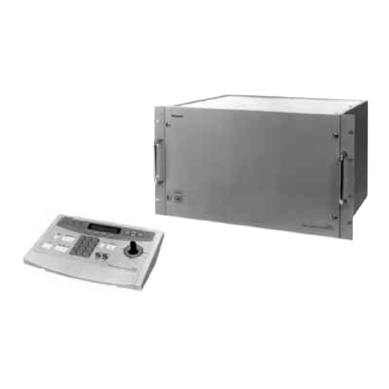
Matrix switcher and system controller
Hide thumbs
Also See for WJ-SX550A:
- Operating instructions manual (135 pages) ,
- Operating instructions manual (132 pages)

Related Manuals for Panasonic WJ-SX550A


Summary of Contents for Panasonic WJ-SX550A
- Page 1 Matrix Switcher WJ-SX550A System Controller WV-CU550A Before attempting to connect or operate this product, please read these instructions completely...
- Page 2 If you lose the fuse cover the plug must not be used until a replacement TO REDUCE THE RISK OF ELECTRIC SHOCK, cover is obtained. DO NOT REMOVE COVER (OR BACK), NO USER A replacement fuse cover can be purchased from your local Panasonic SERVICEABLE PARTS INSIDE. Dealer. REFER SERVICING TO QUALIFIED SERVICE IF THE FITTED MOULDED PLUG IS UNSUITABLE FOR THE SOCK- PERSONNEL.
- Page 4 There are no user-serviceable parts lished for customized security requirements. inside. The use of modular construction for the WJ-SX550A Matrix Do refer all servicing to qualified service personnel. Switcher allows for flexible expansion for future needs. • Handle the unit with care.
-
Page 5: Basic Operation Of A Matrix Switcher
HOW TO USE THIS MANUAL The purpose of this manual is to provide step-by-step instructions for setting up and operating a Matrix System 500. If Matrix Switchers are new to you, it is highly recommended that you read this manual in its entirety. If you are already familiar with Matrix Switchers you might want to skip over Section 1, Basic Operation of a Matrix Switcher, and go directly to Section 4, Installation and System Connections. - Page 6 TABLE OF CONTENTS §1 BASIC OPERATION OF A MATRIX SWITCHER PAGE 5 - 10 §2 FEATURE OF THE SYSTEM 500 MATRIX SWITCHER PAGE 11 - 22 §3 DETAILED PRODUCT DESCRIPTION AND SELECTION PAGE 23 - 48 §4 INSTALLATION AND SYSTEM CONNECTIONS PAGE 49 - 64 §5 SOFTWARE SETUP...
- Page 8 BASIC OPERATION A MATRIX SWITCHER...
-
Page 9: Basic Operation Of A Matrix Switcher
BASIC OPERATION OF A MATRIX SWITCHER Crosspoint Switches Camera 1 SW11 SW21 SW31 SW41 Camera 2 SW12 SW22 SW32 SW42 Camera 3 SW13 SW23 SW33 SW43 Camera 4 SW14 SW24 SW34 SW44 Camera 5 SW15 SW25 SW35 SW45 Camera 6 SW16 SW26 SW36... - Page 10 Activation of crosspoint switches Matrix Switcher Crosspoint Switch Sequence Pattern Timer Memory SW11 SW21 SW31 SW41 SW12 SW22 SW32 SW42 SW13 SW23 SW33 SW43 SW14 SW24 SW34 SW44 SW15 SW25 SW35 SW45 SW16 SW26 SW36 SW46 SW17 SW27 SW37 SW47 SW18 SW28 SW38...
- Page 11 Units, Zoom Lenses and auxiliary circuits through the use of Control Data multiplexed with the video signals. Also, in cases of Panasonic Matrix Switchers, a unique signal called VD2 is multiplexed with the video signals and is used to syn- chronize Panasonic cameras to prevent picture rolling during switching between cameras.
- Page 12 • Examples of Advanced Applications As previously described, the Matrix Switcher controls both the crosspoint switches and external devices. By combining these two functions, complicated Systems Control applications can be implemented as shown below. Receiver Camera 1 Camera 5 Camera 4 Pre 1 Pre 2 Aux 1...
- Page 13 Alarm 3 input by infrared sensor Monitor 1 Step (1) Camera 1 picture is shown for 1 second (2) Camera 4 picture at preset 1 position is shown for 3 seconds (3) Camera 4 picture at preset 2 position is shown for 2 seconds (4) Gate open (Auxiliary 1) Light on (Auxiliary 2) Camera 5 picture is shown for 30 seconds...
- Page 14 FEATURES OF THE SYSTEM 500 MATRIX SWITCHER -11-...
- Page 15 Also, access to the Programming Set Up Menu may be gained through the system controller. VCR: Up to 16 VTRs can be connected. The video signal controlled by the WJ-SX550A Matrix Switcher is supplied to the VTR. Also, the Matrix Switcher can supply the VTRs with an alarm output signal to switch time lapse recording mode.
-
Page 16: Camera
These items are described in more detail on page WV-RC150 Monitor-1 Monitor-2 Operator Name: Mike Operator Number: Operator Level: WJ-SX550A Password: 07171 Priority: Operator Name: Robert Controller Operator Number: Operator Level:... -
Page 17: Camera
See page 20 This control is used to open or close the iris of specified for more details. DC servo lens with Panasonic WV-BP510, or WV-CP610 2. The desired monitor is presently selected by series cameras. - Page 18 This control is available with the Panasonic WV-CS500 or WV-CS600 Combination Camera, which enables the setting and recalling of the Preset function from the System Controller.
- Page 19 • Auto Skip Function The Auto Skip function is available in sequence. If there is no video signal present at a step, the sequence will automatically skip that step. This function is enabled with the Programming Set Up Menu. • Dwell Time The amount of time each camera is displayed on the monitor (Dwell Time) can be set from 1 sec.
- Page 20 The applicable units for camera site alarm inputs are the WV-RC100, WV-RC150 and WV-RC170 Receivers. 2. Interface Alarm This alarm signal is supplied from the Alarm Input Connector on the optional Alarm Board installed in the WJ-SX550A Matrix Switcher. Up to 128 alarm inputs are available.
- Page 21 Any sequence, preset and auxiliary control Alarm Any monitors 8-3. Alarm Recall The WJ-SX550A Matrix Switcher can store up to 99 Alarm Events in its memory. The alarms may be recalled and displayed, in chronological order, on any desired monitor. -18-...
- Page 22 9. Operator Registration In the Operator Registration, an operator's level, priority, password and camera access limits are determined. Up to 30 operators may be registered. For example: OPE-1 Priority OPE-2 OPE-3 OPE-4 12123 Level 1 MENU 12243 12341 12443 CAMERA TITLE Level 2 TIMER PROG SEQ...
- Page 23 11. Status Display M o n i t o r C a m e r a M o d e C T R L R O p e r a t o r P r i o r i t y S P O T C A M S P O T...
- Page 24 Setting Procedure 1. Operator No.1 has first priority . Cameras 1 - 8 can be selected by MON-1. 2. Operator No.2 has second priority. Cameras 1-5 can be selected by MON-2 (limited access due to operator partitioning). 3. Operator No.3 also has second priority. Cameras 4 - 8 can be selected by MON-3. Operator's Partitioning Operator's...
- Page 25 The recommended printer to use is the Panasonic KX-P1624 Impact Dot Matrix Printer. 20. RS-232C Port This port used for connecting with a Personal Computer. The memory of the WJ-SX550A Matrix Switcher can be loaded or saved. Also, a Personal Computer can be substituted for the WV-CU550A System Controller.
- Page 26 DETAILED PRODUCT DESCRIPTION SELECTION -23-...
-
Page 27: Major Operating Controls And Their Functions
VIDEO OUT2 1. Operation Indicator (OPERATE) 5. Video Output Board (OUTPUT) This indicator lights up when the WJ-SX550A Matrix The monitors connect to this board. Switcher is turned power on. Refer to the Video Output Board on page 32 for more details. - Page 28 2. Time Adjustment Input Connector (TIME ADJUST IN) PRINTER This connector accepts the time adjustment signal from a Time Lapse VTR. It enables the time display of the WJ-SX550A Matrix Switcher and the Time Lapse VTR to be matched. Pin No. Designation...
- Page 29 By changing the position of jumper connector (CN14) on the board, this connector can be used as the monitor output for the system status display. (Set Up Menu is displayed during Set up mode.) Caution This board should be installed in the WJ-SX550A Matrix Switcher even if the WJ-AD550 Extension Unit is used. -26-...
- Page 30 CPU Board Dip Switch and Jumper Setting CN12 CN13 CN14 1. Confirm Switches (SW2) on the board are set to the following positions. Note These switches are used only for factory test. Always keep these switches in the positions shown on right in the field. 2.
- Page 31 2. Test Port (TEST 1, 2) These ports are used only for factory test. DATA 6 Caution DATA 7 This board should be installed in the WJ-SX550A Matrix Switcher even if the WJ-AD550 Extension Unit is used. DATA 8 TEST 1 TEST 2...
- Page 32 Control Board Dip Switch Setting Confirm switches (SW2) on the board are set to the following positions. Note These switches are used only for factory test. Always keep these switches in the “OFF” positions in the field. -29-...
- Page 33 WV-PB5508E Video Input Board Video Output Connector (VIDEO OUT 1, 2) The video signal connected to the Camera Input Connector (CAMERA IN) is looped through to INPUT this connector with 75 ohms termination. VIDEO OUT1 The camera control signal multiplexed on the video signal has been eliminated at this connec- tor.
- Page 34 • The Board Number 1 to 8 should be installed in the WJ- SX550A Matrix Switcher and the Board Number 9 to 16 are 89-96 installed in the WJ-AD550 Extension Unit. Do not install more than nine(9) boards in the WJ-SX550A Matrix Switcher. 97-104 105-112...
- Page 35 WV-PB5504AE Video Output Board Alarm Output/Reset Output Connector (ALARM OUT/RESET OUT) External Timing Input Connector (EXT TIMING IN) Recover Input Connector (RECOVER IN) ALARM OUT: When the Matrix Switcher receives an alarm from the WV-PB5564E Alarm Board or camera site receivers WV-RC100, WV-RC150 or WV-R170, the alarm output signal is provided at this connector for the Time Lapse VTR.
- Page 36 E/A/B/G EIA standard CCIR standard SPECIFICATIONS Scanning: 525 lines / 60 fields / 30 frames 625 lines / 50 fields / 25 frames Horizontal: 15.734 KHz 15.625 KHz Vertical: 59.94 Hz 50 Hz Horizontal Resolution: 570 lines Video Output: 1.0 Vp-p NTSC composite 75 ohms 1.0 Vp-p PAL composite 75 ohms Signal-to-Noise Ratio: 00 dB (AGC OFF)
- Page 37 Extension Unit is used. 13-16 • The Board Number 1 to 4 should be installed in the WJ-SX550A Matrix Switcher and the Board Number 5 to 8 are installed in the WJ- AD550 Extension Unit. Do not install more than five (5) boards in the WJ-SX550A Matrix Switcher.
- Page 38 WV-CU550A System Controller ALARM BUSY BACK FORWARD IRIS RESET SEQ ALT PRESET CLOSE OPEN LEFT RIGHT ZOOM FOCUS DOWN -1CAM +1CAM STOP TELE NEAR WIDE System Controller WV-CU CONTROLLER DATA CONTROLLER UNIT NO. MODE TERM -34-...
- Page 39 1. Alarm Indicator (ALARM) AF: This switch is used to activate the auto focus This LED indicator blinks to indicate an alarm condi- function when selected the specified camera tion exists. such as the WV-CS600 Combination Camera. 2. Busy Indicator (BUSY) 11.
- Page 40 22. Data Input/Output Connectors (DATA IN, OUT) These connectors are used to transmit/receive control data to/from the WJ-SX550A Matrix Switcher in a sys- tem. 23. Termination Switch (TERM ON/OFF) This switch is used to enable termination of this con- troller’s data connector.
- Page 41 Extension Unit WJ-AD Extension Extension DATA DATA ADDRESS ADDRESS POWER WJ-SX550A WJ-SX550A WJ-AD550 WJ-AD550 11A00001 1. Operation Indicator (OPERATE) 3. Voltage Indicator (+9V, +5V, –5V) This indicator lights up when the WJ-AD550 Extension These LEDs indicate the presence of +9V, +5V and Unit is turned power on.
- Page 42 3. WJ-SX550A Indicator (WJ-SX550A) DATA ADDRESS This indicator lights up if the board is installed in the WJ-SX550A Matrix Switcher after making switch setting. 4. WJ-AD550 Indicator (WJ-AD550) This indicator lights up if the board is installed in the WJ-AD550 Extension Unit after making switch setting.
- Page 43 2. Set the Data Unit Address Switch on the board to meet the WV-PB5548E Data Boards as shown below. 1) The board installed in the WJ-SX550A Set the switches to the “ON” positions to meet the identification number of the Data Boards where installed in the WJ-AD550 Extension Unit.
- Page 44 WV-PB5564E Alarm Board Alarm Number display This display indicates the alarm input number when the associated alarm sensor unit is activat- Note: The display indicator lights up as shown below when the alarm number is over one hun- dred. indicator ALARM MODE TEST...
- Page 45 Alarm Input Connector (1-32, 33-64) This connector accepts the alarm signals, either normally open or normally closed, from the associated alarm sensor unit. Normal Condition Alarm In Alarm Signal (Open) Alarm Sensor (Close) Alarm Sensor 100 msec. Normally Open (NOR OPEN) (Close) Alarm Sensor (Open) Alarm Sensor 100 msec.
- Page 46 WV-PB5564E Alarm Board Dip Switch Setting 1. Set switches (SW1) on the board to meet the alarm input number as shown below. BOARD ALARM SW1 SETTING INPUT NO. 1-64 UNIT ADR 65-128 UNIT ADR SW12 2. Set switches (SW4 - SW11) on the board to meet the Alarm Input Switch No.
- Page 47 WV-PB5548E Data Board 1. Data Connector (TA/TB/RA/RB/GND, 1 - 8) These connectors are used to transmit/receive control data to/from the camera site. Use data grade cable, suitable for RS-485 (shielded, twisted pairs). Cable length may be extended up to 1,200 m (4,000 ft). TA (+) DATA (RS485)
- Page 48 WV-PB5548E Data Board Dip Switch Setting 1. Set switches (SW1) on the board to meet the data board number as shown in the following table. Initially, board number 1 is selected at the factory. BOARD SW1 SETTING SW100 SW150 SW200 SW250 SW300 SW350...
-
Page 49: Board Selection For System Expansion
The CPU and Control Board, along with one Video Input Board and one Video Output Board are supplied as standard acces- sories. Depending on the number of camera inputs and monitor outputs required, additional WV-PB5508E Video Input Boards, WV- PB5504AE Video Output Boards will be required. • WJ-SX550A Matrix Switcher CONTROL INPUT OUTPUT... - Page 50 The following table shows components required for various system configurations. Extension Unit Input Boards Output Boards Cameras Monitors Slots Used Slots Left WJ-AD550 WV-PB5508E WV-PB5504AE 1 - 8 1 - 4 not required 9 - 16 1 - 4 not required 17 - 24 1 - 4 not required...
- Page 51 Extension Unit Input Boards Output Boards Cameras Monitors Slots Used Slots Left WJ-AD550 WV-PB5508E WV-PB5504AE 1 - 8 9 - 12 not required 9 - 16 9 - 12 not required 17 - 24 9 - 12 not required 25 - 32 9 - 12 not required 33 - 40...
- Page 52 -48-...
- Page 53 INSTALLATION SYSTEM CONNECTIONS -49-...
- Page 54 Side Panel Rack Mount Screws Remove screws. Tighten Palm-rest Rack Angle Bracket screws. WJ-SX550A Matrix Switcher Mounting into the Rack Rubber feet 1. Remove four rubber feet by removing four screws on Rubber the bottom of the Matrix Switcher. feet Remove Screws 2.
- Page 55 • Extension Unit is not required. Rear Panel Caution Before installing any boards be sure to turn off the Power Switch of the WJ-SX550A Matrix Switcher. 1. Remove the screws from the rear panel(s) of the Matrix Switcher. Remove four screws.
- Page 56 Caution Before installing any boards, be sure to turn off the Remove screws. Power Switch of the WJ-SX550A Matrix Switcher and WJ-AD550 Extension Unit. When the Extension Unit is required to install the boards, it is recommended to install the boards as shown below.
-
Page 57: System Connections
SYSTEM CONNECTIONS Combination Camera Max. 128 cameras Receive Receiver WJ-SX550A Matrix Switcher Computer RS-232C Port Extension CONTROL INPUT INPUT INPUT INPUT INPUT INPUT INPUT INPUT OUTPUT OUTPUT OUTPUT OUTPUT VIDEO OUT1 VIDEO OUT1 VIDEO OUT1 VIDEO OUT1 VIDEO OUT1 VIDEO OUT1... -
Page 58: Connection With The Camera Sites
Input Connectors (CAMERA IN, 1-8) on the Video Input Board. Caution: Make sure that the cable length between the camera site and the WJ-SX550A Matrix Switcher is less than 1,200m (4,000 ft) when using 5C - 2V coaxial cable or equivalent. -
Page 59: Connection With The Monitors
Connection with the Monitors Connect the Monitors to the Monitor Output Connec- tors (MONITOR OUT) on the Video Output Board(s). ALARM ALARM WARNING SERIES REC IN SERIES 1 SHOT IN HUMID OUT REC OUT ALARM TIME REC OUT CAMERA RESET IN ADJUST IN SW OUT ALARM... - Page 60 RS-485 (2 shield, twist- installed in a Matrix System. ed pairs) is used. The Control Board installed in the WJ-SX550A Matrix Low grade cable will result in unstable operation of the Switcher has eight ports that correspond to eight WV- system.
- Page 61 • Direct connection between the Control Board and System Controllers (“Home Run” Type Wiring) In this type of installation there is one control cable directly connecting each System Controller to one Control Board port. Refer to the connections and controller settings shown below. Matrix Switcher WJ-SX550A Control Board CONTROL...
- Page 62 In this type of installation only one control cable directly connects between System Controller #1 and the Control Board. The rest of the System Controllers connect to System Controller #1 in a Daisy-Chain type of connection. Refer to the connections and controller settings shown below. Matrix Switcher WJ-SX550A Control Board CONTROL...
- Page 63 In this type of installation there is a mixture of wiring methods,with some System Controllers connecting directly to the Control Board while other System Controllers connect to the Control Board through other System Controllers. Refer to the connections and controller settings shown below. Matrix Switcher WJ-SX550A Control Board CONTROL...
- Page 64 Connection with the Alarm Sensor Units 1-32 Connect the sensor switches to the Alarm Input Common (Ground) Connector on the Alarm Board as shown in the exam- ple below. Alarm Sensor Alarm Sensor Alarm Sensor Designation Designation Pin No. Pin No. Board No.1 Board No.2 Board No.1...
- Page 65 Connection between the Data Board and Camera Site Connect the Data Board and the Camera Controller by DATA (RS485) specified data cable. Basically, connect shown right. DATA Then the following settings should be made by using the T(A) T(B) R(A) R(B) Setup Menu.
- Page 66 The Camera Status Display only works correctly while the camera power is turned on. Set the same Communication Parameters on the Setup Menus of the Matrix Switcher and Camera Controller. Models Matrix Switcher Camera Controller Parameters WJ-SX550A WV-RM70E F/H Duplex Full or Half Baud Rate 19200...
- Page 67 • Indirect Connection between the Data Board and Camera Controllers (“Daisy-Chain” Type Wiring) In this type of connection only one control cable directly connects between the Data Connector #1 and the Camera Controller #1. The rest of the Camera Controllers connect to Camera Controller #1 in a Daisy-Chain of connection. Refer to the connec- tions and settings shown below.
- Page 68 Set the Matrix Switcher and the Camera Controllers (up to 8) shown below. Models Matrix Switcher Camera Controller Parameters WJ-SX550A WV-RM70E F/H Duplex : Full Daisy Camera In Number #1 - - - Unit Number : Camera In Number #2 - - -...
- Page 69 SOFTWARE SETUP -65-...
- Page 70 SET UP MENU Executes the setting or Selection. The Set Up Menu provides a way for controlling functions not available through direct keyboard input. It is accessi- ble to system operators with the proper operator level. The Set Up Menu also provides access for system program- ming to authorized operators.
-
Page 71: Table Of Contents
Set Up Programming Menu As shown below, the Set Up Menu has six main sub menus: Program, Operator, Camera Title, Alarm Recall, Status and System. Three of these sub menus; Program, Operator and System, are further divided in to additional submenus. Set Up Program Program Sequence .................. -
Page 72: Set Up
1. Set Up Menu After selecting the Set Up Menu on mode, the Set Up Menu allows access to six items as shown below.. P r o g r a m O p e r a t o r C a m e r a T i t l e A l a r m R e c a l l... -
Page 73: Program Sequence
3. Program Sequence (P-SEQ) After selecting the Program Sequence sub menu, a table appears on the monitor. This table is used to programme or edit a Program Sequence. A Program Sequence is a series of 64 steps assigned to a particular monitor. -
Page 74: Tour Sequence
4. Tour Sequence (T-SEQ) This table is used to programme or edit a Tour Sequence. There are 32 Tour Sequences available, each with 64 steps. Each step consists of a camera number, a dwell time, an associated Pan/Tilt preset position address (if applicable), and auxiliary switches 1 and 2. -
Page 75: Group Sequence
5. Group Sequence (G-SEQ) This table is used to programme or edit a Group Sequence. A Group Sequence consists of up to 64 steps. Each step can assign to a maximum of 16 monitors, 16 cameras, each with preset position (if applicable) and AUX 1 and AUX 2 control. There are 8 Group Sequences available in this system. - Page 76 6. Timer Menu As shown below, the Timer Menu allows access to two items, Event and Special Day Schedule. With these two items it is possible to enable or disable Tour and Group Sequences on selected monitors based on time of day, day of the week, and user-definable special days.
-
Page 77: Timer Event Schedule
8. Timer Event Schedule This table is used to enable and disable Tour and Group Sequences according to the time of day and day of the week. There are 45 events available in one day. S e t P R O G . T i m e r E v e n t S U N . -
Page 78: Special Day Schedule
9. Special Day Schedule Before programming this table, confirm that the Timer Event Schedule (Special Day 1-5) is programmed completely. This table allows for up to 48 days to be defined as special days. In the Timer Event Schedule there are 5 tables where the special days 1 through 5 are programmed for sequences. -
Page 79: Alarm Menu
10. Alarm Menu As shown below, the Alarm Menu allows access to five items: Alarm Mode Select, Set Up Alarm Modes 1-3 and Timer Alarm Schedule.. S e t P R O G . A l a r m A l a r m M o d e S e l e c t S e t... -
Page 80: Alarm
11. Alarm Mode Select There are 5 Alarm modes available, Mode-1, Mode-2, Mode-3, Off mode and Timer mode. In Alarm mode-1, All alarm inputs are displayed in sequential order on monitor #1. In Alarm mode-2, All alarm inputs are displayed in sequential order on monitors #1 through #4. In Alarm mode-3, Any alarm input can be displayed on any monitor, along with preset (if applicable) and AUX 1 and 2 control. -
Page 81: Set Up Alarm Mode
12. Set Up Alarm Mode 1 This table can be set up only after the alarm mode is set to the Off mode in the Alarm Mode Select table. S e t P R O G . A l a r m M o d e 1 S e t A l a r m... -
Page 82: Set Up Alarm Mode
13. Set Up Alarm Mode 2 This table can be set up only after the alarm mode is set to the Off mode in the Alarm Mode Select table. S e t P R O G . A l a r m M o d e 2 S e t A l a r m... -
Page 83: Set Up Alarm Mode
14. Set Up Alarm Mode 3 This table can be set up only after the alarm mode is set to the Off mode in the Alarm Mode Select table. There is a total of 110 programmable alarm functions available through 10 pages of tables. S e t P R O G . - Page 84 The follows are explanation on the setup example 1 to 6 in the table. 1. Spot (S) Setup example 1 When an Alarm is activated, it is able to display the desired camera picture on the desired monitor. Example 1 shows: An Alarm 1 is activated, Monitor 1 displays Camera 1 picture at preset 1 position.
-
Page 85: Timer Alarm Schedule
15. Timer Alarm Schedule This table can be set up only after the alarm mode is set up to the Off mode in the Alarm Mode Select table. This table is used to enable and disable the Alarm Modes according to the time of day and day of the week. S e t P R O G . -
Page 86: Operator
16. Operator Menu The operator menu allows access to two items, the level table and operator registration. S e t O P E . L e v e l T a b l e O p e r a t o r R e g i s t r a t i o n F 1 : - - F 2 : - -... -
Page 87: Operator Registration
18. Operator Registration This table is used to establish operator numbers for the users of the system, along with associated passwords, operator levels and priorities. Up to 30 operators may be registered. Additionally, operator limits for camera access are set in this table. S e t O P E . -
Page 88: Camera Title
19. Camera Title There are 128 camera titles available. Each title is composed of 15 characters per line, times 2 lines. S e t C A M C a m e r a T i t l e C A M T i t l e A B C D E F G H I J K L M N 1 s t... -
Page 89: Alarm Recall
20. Alarm Recall There are 99 alarm records stored in chronological order in 7 pages of tables. The tables also show all involved monitor numbers when Alarm Mode-3 is activated, and indicates the alarm mode number when Alarm Mode-1 or Alarm Mode-2 is activated. S e t R E C A l a r m... -
Page 90: Controller
22. System Menu As shown below, the system menu allows access to six items. S e t S y s t e m C o n t r o l l e r E X T T i m i n g S e l e c t C o m p e n s a t i o n / V D 2 R S - 4 8 5 S i t e C o m m u n i c a t i o n C o m m u n i c a t i o n... -
Page 91: Ext Timing Select
24. EXT Timing Select This table permits the sequence dwell time on the selected monitor to be synchronized with the time lapse mode set in the associ- ated Time Lapse VTR. S e t S y s t e m E X T . -
Page 92: Compensation/Vd2
25. Compensation/VD2 This table is used to for selecting the most suitable position of the cable-loss compensator and to turn on or off the VD2 (Sync. sig- nal) or the control data for the cameras. S e t S y s t e m C O M / V D C o m p e n s a t i o n / V D 2 P a g e... -
Page 93: Site Communication
26. RS-485 Site Communication This table is used to set the Communication Parameters between the Data Boards installed in the Matrix Switcher and the Camera Site.. S e t S y s t e m R S - 4 8 5 R S - 4 8 5 S i t e C o m m u n i c a t i o n B o a r d A d d r . -
Page 94: Communication Speed
27. Communication Speed This table is used to set the Communication Parameters between the System Controllers (or PCs) and the Matrix Switcher. S e t S y s t e m S p e e d C o m m u n i c a t i o n S p e e d B a u d W a i t D a t a... -
Page 95: Clock
28. Clock Set This table is used to set the present time and date. Note: The date and time are updated when the Escape (ESC) Key is pressed. S e t S y s t e m C l o c k C l o c k S e t D a y... - Page 96 -92-...
- Page 97 OPERATING PROCEDURES -93-...
- Page 98 C h a r a c t e r T y p e V D / V S Caution : If the WJ-AD550 Extension Unit is used in the system, turn the Extension Unit power on before turning power on the WJ-SX550A Matrix Switcher. -94-...
- Page 99 Operator No : Caution: If the WJ-AD550 Extension Unit is used in the system, turn the Extension Unit power on before turning power on the WJ-SX550A Matrix Switcher. 2. Press the Controller On/Off Switch located on the rear of the System Controller, to the ON position.
- Page 100 If an Operator No. or Password error has occurred, a ‘Monitor busy’ will appear on the LCD when another ‘No entry’ display appears on the LCD and the display controller, with a higher operator priority, is presently automatically returns to the Log-in display. controlling the monitor outputs.
-
Page 101: Alarm
2. Operation Menus After log-in, the following operation menus are available on the LCD by pressing the appropriate Cursor Keys. For example, to go from the CAMERA/MONITOR SELECTION MENU (A1) to the SHUTTER SELECTION MENU (C1) press the right Cursor Key twice. To go from the G-SEQ SELECTION MENU to the SET UP MENU, press the down Cursor Key four times. - Page 102 3. Monitor Selection Press the Increment (INC + 1 CAM) Switch to replace the presently selected camera with the next higher camera number. Select the desired monitor by pressing the Numeric Keys, then press the Monitor (MON) Key. +1CAM Camera Monitor 01 Press the Decrement (DEC 1 CAM) Switch to replace the presently selected camera with the next lower camera...
- Page 103 Press the Auto Focus (AF) Switch to adjust the lens ing the Function (F1) Key, to adjust fine. focus automatically, when specified camera with the auto focus feature, such as the Panasonic WV-CS600, Note: Press the Focus, Zoom or Iris Switch, while is used.
- Page 104 6-3 Pan/Tilt Control (Preset Operation) 3. Press the Function (F4) Key to display the menu shown below. The following function is only available with cameras that have preset panning functions, such as the Panasonic WV- CS500 and WV-CS600. CAM-P Mode Off Exit 1.
-
Page 105: Camera
6-5 Pan/Tilt Control (Auto/Random Panning) 6-6 Camera Power and Housing Control The functions described below are available only when the For remote camera power operation, a 24V AC powered specified Pan/Tilt Head is used. camera must be installed in the housing. 1. - Page 106 7. Running a Sequence 4. Press the Stop (STOP) Switch to stop the Program Sequence. 7-1 Program Sequence STOP The following functions are available only if a Program Sequence has been previously established for a particular monitor through the Set Up Menu. As described on page 69, the Program Sequence can display up to 128 cameras in a predetermined series on a selected monitor.
- Page 107 8. Press the Decrement (DEC - 1CAM) Switch to move a 2. Select the desired Tour Sequence number by press- sequence one step backward from the step that was ing the Numeric Keys. previously stopped by the Stop (STOP) Switch. Camera -1CAM Monitor 16...
- Page 108 6. Press the Backward Sequence (BACK SEQ) Switch to 7-3 Group Sequence continue a sequence that was previously stopped by the Stop (STOP) Switch. The sequence will continue in The following functions are available only if a Group the reverse direction from the step that was selected Sequence has been previously established through the Set at the time the Stop Switch was pressed.
- Page 109 5. Press the Stop (STOP) Switch to stop the Group Sequence. -1CAM STOP G-Seq 01 Stop Monitor 16 G-Seq 01 Stop Monitor 16 10. Press the Forward Sequence (FORWARD SEQ) Switch, after pressing the Alternate (ALT) Switch, to 6. Press the Forward Sequence (FORWARD SEQ) start the Group Sequence from the beginning of the Switch to continue a sequence that was previously sequence pattern that was previously stopped by the...
- Page 110 9. Title Display 5. Press the Function (F3) Key repeatedly to display or erase the date and time from the monitor. 1. Select the desired camera and monitor. Refer to the Camera and Monitor Selection on page Camera 07,MAY'96 14:23:56 Monitor 16 2.
- Page 111 10. Camera Operation 10-2 Electronic Sensitivity Up Mode The following function is available only when specified 10-1 Electronic Shutter Mode cameras with the electronic sensitivity feature are used. The following function is available only when specified 1. Select the desired camera and monitor. cameras with the electronic shutter feature are used.
- Page 112 Press the Function (F3) Key to select a lower sensitivi- 4. Press the Function (F3 or F4) Key repeatedly to select ty up setting or press the Function (F4) Key to select a the desired zoomed area. The zoomed area is higher sensitivity up setting.
- Page 113 Camera Monitor 16 The following function is available only when specified cameras with the preset feature, such as the Panasonic WV-CS500 or WV-CS600, are used. 2. Select the BLC (D2) Menu on the LCD by pressing 1. Select the desired camera and monitor.
- Page 114 Function (F3) Key to reset all set- The following functions are only available with cameras tings to initial state. that have set up functions such as the Panasonic WV- CP610 or WV-BP510 series, WV-CS600 or WV-CS400 cam- eras.
- Page 115 11. Camera Status Display 13. Alarm Control 1. Select the desired camera and monitor. 13-1 Alarm Input Selection Refer to the Camera Selection and Monitor Selection on page 98. The following function is used to change the alarm input selection by the System Controller After making the Alarm Mode Select setting in the Setup Menu.
- Page 116 Note: “AL0” or “AL1” is displayed on the upper right 14. Preset Setting (WV-CS500 Only) corner of the alarmed monitor. The following function is only available with the cameras that have preset panning functions, such as the Panasonic WV-CS500. 07,MAY'96 14:23:56 14-1 Preset Menu Setting 1.
- Page 117 14-2 Preset Program Menu 1. Move the cursor to the desired preset number by mov- ing the Joystick Controller. 2. Press the Set (SET) Key, the Preset Position Setting As shown below, the Preset Program Menu has three sub table appears on the monitor. menus: SET UP PRESET, SET HOME POSI (Position), and PRESET TEST.
- Page 118 14-4. Home Position Setting 14-6 Clear the Preset Settings After selecting the SET HOME POSI sub menu, a table 1. Select the desired camera and monitor. titled HOME POSITION, appears on the monitor. Refer to the Camera Selection and Monitor Selection on page 98.
- Page 119 15. Camera Position Number Setting 5. Enter the Camera Position Number by pressing the Numeric Keys. When completed above steps, press the Set (SET) The following function is available only when the Mode Key to execute the selection. Selection Switch is selected at CAM-P Mode on the rear of If made mistake on the above steps, press the Escape the System Controller.
- Page 120 5. Confirm the display on the LCD, then press the Set 5. The above function will automatically stop and dis- (SET) Key to delete the selected Camera Position plays on the LCD shown below Number. Press the Function (F4) Key to return to the previous If made mistake on the above steps, press the Escape Camera Position Menu.
- Page 121 16. Priority Lock 17. Log-Out This function is used to retain control of a monitor by an This function is used when an operator is leaving the con- operator, even after that operator has selected another troller, or no longer requires access to the system. monitor or has logged out.
- Page 122 -118-...
-
Page 123: Troubleshooting
TROUBLESHOOTING -119-... - Page 124 2. Check that the ON/OFF switch, located in the rear of the WV-CU550A System Controller, is turned on. Symptom: System Controller(s) will not log-in. 1. Ensure that the System Controller(s) is plugged into the correct ports on the Control Board of the WJ-SX550A Matrix Switcher. The two ports labeled “Test” do not support System Controller inputs.
- Page 125 Symptom: While running the Preset Test, the WV-CS500 Combination Camera stops at preset positions for extended periods of time. 1. If the WV-CS500 had it’s preset positions originally programmed by other systems, there are dwell times associated with those positions that will determine how long the Preset Test will take. Re-programme the presets by using the Matrix Switcher to eliminate the dwell times.
- Page 126 Symptom: The Alarm does not work. 1. Check that the Alarm Mode is selected “ Mode 1 - 3 “ or Timer on the Alarm Mode Select Menu in the Set Up Menu. 2. Check that the Alarm Input (Site or Board) is selected “On” on the Alarm Mode Select Menu in the Set Up Menu. Symptom: The sequence does not finish even after the programmed time.
-
Page 127: Specifications
SPECIFICATIONS -123-... - Page 128 SPECIFICATIONS WJ-SX550A Matrix Switcher General Power Supply: 220-240V AC 50 Hz Power Consumption: Approx. 20W (Max. 75W with all optional boards installed) Max. Number of Video Input Board: 8 (total 64 Input) Max. Number of Video Output Board: 4 (total 16 Output) Max.
- Page 129 WV-PB5504AE Video Output Board Monitor Output (1 - 4): 1.0V[p-p]/75Ω composite video signal Monitor Input (1 - 4): 1.0V[p-p]/75Ω composite video signal Alarm Output (1 - 4): Open collector output: 16V DC 100mA max. Reset Output (1 - 4): Pulse (VTR): +5V DC 500ms or Open collector output: 16V DC 100mA max.
- Page 130 WV-PB5548E Data Board Data Input/Output(1 - 8): RS-485 (Full Duplex or Half Duplex, selectable inside the switch) [5-pin T(A), T(B), R(A), R(B), GND] X8 use with shield, twisted pairs data cable Transmitting Speed (Baud Rate); 1200 - 19,200 bps Max. Cable Length: 1,200 m (4,000 ft) Max.
- Page 131 INDEX -127-...
- Page 132 INDEX Camera Set Up Menu ............ 110 Camera Site Alarm ............17 Camera Status ............... 111 Alarm Acknowledge and Reset Switch ....36, 111 Camera Title ............19, 67, 84 Alarm Board ........12, 32, 40, 42, 47, 60 Cam-Power and Housing Menu ........101 Alarm Indicator ............
- Page 133 Focus Control ..........35, 98, 99, 113 Numeric Key ..............35 Forward Sequence ............ 20, 85 Forward Sequence Switch ....36, 102, 103, 104, 105 Full Duplex ..............44, 89 Function Key ..............35 On Screen Display ............22 Operator Level ..........13, 19, 82, 83 Operator Limit ............
- Page 134 Sens Up Menu ............... 107 Zoom Control ..........35, 98, 99, 113 Sequence ..........6, 15, 74, 102, 103 Zooming Position Mode ..........109 Sequence Pattern ..........103, 104 Set Key ................35 Set Up ............... 20, 85 Set Up Menu ....... 66, 67, 68, 102, 103, 104 Shutter Menu ..............
- Page 135 -131-...
- Page 136 DEUTSCHE AUSGABE (GERMAN VERSION) Die in dieser Bedienungsanleitung aufgeführten Modellnummern weisen keinen Anhang auf. CAUTION RISK OF ELECTRIC SHOCK DO NOT OPEN WARNUNG: WEDER DECKEL NOCH RÜCKPLATTE ABNEHMEN, UM DIE GEFAHR EINES ELEKTRISCHEN SCHLAGS ZU VERMEIDEN. DAS GERÄT ENTHÄLT KEINE BAUTEILE, DIE VOM KUNDEN GEWARTET WERDEN KÖNNEN.
- Page 138 Matsushita Electric Industrial Co., Ltd. Central P.O. Box 288, Osaka 530-91, Japan N0396-0156 YWV8QA4204BN Printed in Japan N 19 Gedruckt in Japan Imprimé au Japon...