Table of Contents
Advertisement
Advertisement
Table of Contents

Related Manuals for Toshiba RemoteEye II


Summary of Contents for Toshiba RemoteEye II
- Page 1 ® RemotEye User Manual Document Number: 50024-008 November, 2005...
-
Page 2: About This Manual
About This Manual This manual was written by the TOSHIBA Engineering and Marketing Groups. These groups are tasked with providing technical documentation for the RemotEye II system. Every effort has been made to provide accurate and concise information to you, our customer. -
Page 3: Contacting Toshiba's Customer Support Center
Contacting TOSHIBA’s Customer Support Center TOSHIBA’s Customer Support Center can be contacted to obtain help in resolving any RemotEye II system problem that you may experience or to provide application information. The Support Center can be reached at 800-231-1412 (toll free) or 713-466-0277. The center is open from 8 a.m. -
Page 4: Important Notice
Corporation's UPS Division. The sales contract contains the entire obligation of the TOSHIBA International Corporation's UPS Division. The warranty contained in the contract between the parties is the sole warranty of the TOSHIBA International Corporation's UPS Division, and any statements contained herein do not create new warranties or modify the existing warranty. -
Page 5: Table Of Contents
Table of Content About This Manual ....................... 2 Contacting TOSHIBA’s Customer Support Center ............3 Important Notice ......................4 General Safety Instructions ..................7 Important Safety Instructions...................10 Introduction......................... 12 Package Contents ....................13 RemotEye II Features ....................15 Installation ........................17 System Compatibility ....................17 Installing RemotEye II/Internal ................18... - Page 6 Toshiba RemotEye II Application Program.............. 108 Toshiba RemotEye II Client Software..............108 Auto Save-Log Software ..................123 Upgrade RemotEye II ....................128 Hardware Specifications ................... 132 RemotEye II/Internal Hardware Specification ............132 RemotEye II/External Hardware Specification............135 Cables Definition ....................137...
-
Page 7: General Safety Instructions
General Safety Instructions DO NOT attempt to install, operate, maintain or dispose of this equipment until you have read and understood all of the product safety information and directions that are contained in this manual. Safety Alert Symbol The Safety Alert Symbol indicates that a potential personal injury hazard exists. The symbol is comprised of an equilateral triangle enclosing an exclamation mark. -
Page 8: Special Symbols
WARNING The word CAUTION or ATTENTION in capital letters preceded by the safety alert symbol indicates that a potentially hazardous situation exists which, if not avoided, may result in minor or moderate injury. CAUTION / ATTENTION The word CAUTION in capital letters without the safety alert symbol indicates a potentially hazardous situation exists which, if not avoided, may result in equipment and property damage. -
Page 9: Equipment Warning Labels
DO NOT remove or cover any of the labels. If the labels are damaged or if additional labels are required, contact your Toshiba representative for additional labels. Labels attached to the equipment are there to provide useful information or to indicate an imminently hazardous situation that may result in serious injury, severe property and equipment damage, or death if the instructions are not followed. -
Page 10: Important Safety Instructions
Turn off, lockout, and tagout all power sources before connecting the power wiring to the equipment or when performing maintenance. Unauthorized personnel should not service batteries. Contact your nearest Toshiba authorized service center for battery replacement. Qualified Personnel ONLY! Qualified Personnel is one that has the skills and knowledge relating to the... -
Page 11: Installation Precautions
WARNING Misuse of this equipment could result in injury and equipment damage. In no event will Toshiba Corporation be responsible or liable for either indirect or consequential damage or injury that may result from the misuse of this equipment. CAUTION Installation Precautions Install the unit in a well-ventilated location;... -
Page 12: Introduction
UPS or as an external device that connects to the UPS via a provided cable. The RemotEye II/Internal is designed for the Toshiba UPS that has the option slot. The circuit board is connected to the UPS via the RemotEye II/Internal card edge connector. -
Page 13: Package Contents
Tsb3xx.bin, the Current RemotEye II image file, Window.exe, Toshiba RemotEye II Client Software installation file for Window, Unix.exe, Toshiba RemotEye II Client Software installation file for UNIX OS, and RemotEye II User Manual in PDF format. PC cable, a DB9 female to RJ45 cable (Workstation COM port to RemotEye II/Internal COM port). - Page 14 RemotEye II User Manual in PDF format. PC cable, a DB9 female to RJ45 cable (Workstation COM port to RemotEye II/External PC port). UPS cable, a DB9 male to RJ45 cable (Toshiba UPS RS232 port to RemotEye II/External UPS port). The RemotEye II User Manual.
-
Page 15: Remoteye Ii Features
RemotEye II Features Included in the RemotEye II are several support options for managing Toshiba UPS. BOOTP/DHCP Requests The RemotEye II can automatically retrieve its network identity from a network server using the Boot Protocol (BOOTP) or Dynamic Host Configuration (DHCP) automatic configuration technique. - Page 16 This utility allows users to save logs from several RemotEye(s) at the same time to a same or different computer. Client Shutdown The Toshiba RemotEye II Client Software can broadcast system failure messages via an IP (Internet Protocol) packet and perform unattended shutdown of multiple servers operating under a variety of platforms.
-
Page 17: Installation
The RemotEye II is supported by workstations using the following operating systems: Windows 95/98/NT/2000/XP, Macintosh, and Unix. The RemotEye II supports the following Toshiba UPS system families: 1000 Series 1400 S(E) (Plus), 1400 XL Plus, 1400 Super XL Plus Series, 1500 (Plus) Series,... -
Page 18: Installing Remoteye Ii/Internal
Installing RemotEye II/Internal Follow these steps to install the RemotEye II/Internal card. Turn the UPS off using the proper shutdown procedure as explained in the UPS manual. Slide the RemotEye II/Internal printed circuit board into the extension option slot of the UPS. Secure the printed circuit board using the UPS supplied screws.(See Figure 1: RemotEye II/Internal) Figure 1: RemotEye II/Internal... -
Page 19: Installing Remoteye Ii/External
Plug the RemotEye II power adapter into a 120/220 VAC power source. For best results, be sure outlet is powered by a Toshiba UPS. Connect the UPS cable from the RS232 serial port of the Toshiba UPS to the RemotEye II/External UPS port.(See Figure 2: RemotEye II/External) -
Page 20: Making The Network Connection
Making the Network Connection Each Ethernet network is different. Therefore, the following steps should be used as an outline for connecting the RemotEye II to a network: Connect one end of a Category 5 cable to the NETWORK RJ45 receptacle of RemotEye II. -
Page 21: Configuration
Configuration RemotEye II must be configured for proper operation on its network. The RemotEye II offers three convenient methods for configuration. Preliminary Issues RemotEye II is a network device. Several items should be considered prior to communicating with RemotEye II over the network. The following sections cover important topics when placing a device on an Ethernet network. -
Page 22: Default Ip Address
Default IP Address The RemotEye II is initially configured with a default Internet Protocol (IP) address. By default, the 4 bytes composing the default IP address are derived from the MAC address in the following way: 172.18.xxx.yyy where xxx is the decimal value of the MM MAC address byte and yyy is the decimal value of the NN MAC address byte. -
Page 23: Configuring The Remoteye Ii Via Terminal
Configuring the RemotEye II via Terminal The RemotEye II can be configured by directly connecting to the device. Hardware Setup Direct configuration is accomplished through the provided cable. Follow these steps to setup the hardware for direct RemotEye II configuration: Connect the DB9 female end of the PC cable to the terminal or workstation COM port. -
Page 24: Connecting To The Remoteye Ii Via Terminal
Connecting to the RemotEye II via Terminal A direct configuration session can easily be established once the hardware and software are properly set up. Follow these steps to begin configuration: Terminal Emulator Example To configure the RemotEye II from a Windows platform, use Hyperterminal. Hyperterminal is a standard terminal emulator packaged with any Windows operating Launch the Hyperterminal program by navigating to Start →... - Page 25 The seven options provided in the RemotEye II Main Menu provide access to all system RemotEye II configuration parameters. These options (see the Main Menu Description on Figure 4: Console Main Menu) and their submenus are discussed in more detail in the next section. +====================================================================+ [ TIC RemotEye II Main Menu ] +====================================================================+...
-
Page 26: Remoteye Ii Configuration Menu Navigation
(table 1) provides an overview of the entire menu structure. When navigating through these menus, all alpha-numeric characters are acceptable and are case-sensitive. RemotEye II Main Menu (1) Toshiba RemotEye (1) System Group RemotEye II Agent Version II Configuration... - Page 27 (7) Mail Receivers (8) Test Email Configuration (0) Return to Previous Menu (4) EMD Group (1) Temperature Group (2) Humidity Group (3) Alarm-1 Group (4) Alarm-2 Group (5) Devide Status (0) Return to Previous Menu (2) SNMP Communities (1) Modify Table Entry (2) Reset to Default Setting (0) Return to Previous Menu (3) SNMPV3 USM Table...
- Page 28 Main Menu Description The Main Menu of the RemotEye II consists of the following options (see Figure 5: Console Main Menu Description): Toshiba RemotEye II Configuration SNMP Communities SNMPv3 USM Table Trap Receiver Table Reset Configuration to Default. Save and Exit.
- Page 29 Toshiba RemotEye II Configuration Main Menu → ( 1) T oshiba RemotEye II Configuration (see Figure 6: Console Configuration Menu Description). The Toshiba RemotEye II Configuration option provides access to the following system settings: System Group Control Group Parameter Group...
-
Page 30: System Group
System Group Main Menu → T oshiba RemotEye II Configuration → ( 1) S ystem Group (see Figure 7: Console System Group Menu Description). The System Group provides access to the system settings listed below. The settings may be viewed or changed from this screen. - Page 31 +=================================================================+ [ Date and Time Menu ] +=================================================================+ 1. System Date (dd/mm/yyyy) : 09/24/2005 2. System Time (hh:mm:ss) : 12:22:21 3. NTP Server : 0.0.0.0 4. NTP Time Zone : -06:00 5. Daylight Saving Time Control : Enabled 6. NTP Control : Enabled 0.
-
Page 32: Control Group
HTTP Login User Name — The login user name grants write access from a web browser (the default setting is TOSHIBA). Community Read-Only — This common community name provides read- only access to devices within this community. (The default setting is public.) Community Read/Write —... - Page 33 +====================================================================+ [ Control Group Menu ] +====================================================================+ 1. HTTP Login Username : TOSHIBA 2. Community Read-Only : public 3. Community Read/Write 4. BOOTP/DHCP Control : Enabled 5. Telnet Control : Enabled 6. TFTP Upgrade Control : Disabled 7. HTTP Security Control : Disabled 8.
- Page 34 RemotEye II Client Identifier (CID) in DHCP systems. System location — The RemotEye II physical location. Poll Rate — The polling rate in seconds. This determines how frequently RemotEye II updates its data from the Toshiba UPS. (The default setting is Return to previous menu. +====================================================================+...
- Page 35 Mail Server — The Simple Mail Transfer Protocol (SMTP) mail server IP address. If a hostname is used, such as smtp.tic.toshiba.com, the Domain Name Server (DNS) IP address is required on setting #4.
- Page 36 +===================================================================+ [ Email Group Menu ] +===================================================================+ 1. Mail Server 2. User Account 3. User Password 4. Domain Name 5. DNS IP Address : 0.0.0.0 6. Daily Status Report : 00:00 7. Mail Receivers 8. Test Email Configuration 0. Return to previous menu Please Enter Your Choice =>...
- Page 37 EMD Group Main Menu → T oshiba RemotEye II Configuration → ( 5) E MD Group (see on page) The EMD Group menu provides access to the system settings listed below. The settings may be viewed and changed from this screen. Temperature Group —...
- Page 38 SNMP Communities Main Menu → ( 2) S NMP Communities (see Figure 13: SNMP Communities Description). The SNMP Communities lists the status and configuration of access rights that are currently granted and the applicable level of access. The entries in this table are largely responsible restricting SNMP communication with RemotEye II.
- Page 39 SNMPv3 USM Table Main Menu → ( 3) S NMPv3 USM Table (seeFigure 14: SNMPv3 USM Menu Description). The SNMPv3 USM Table lists the status and configuration of access rights that are currently granted and the applicable level of access. The entries in this table are largely responsible restricting SNMPv3 security with RemotEye II.
-
Page 40: Trap Receiver Table
The configuration of the trap receivers shall be as follows: IP Address: IP address of the NMS. Community String: NMS community string. Select Trap Type: None Toshiba Trap JEMA Trap Description: Description of the NMS. +====================================================================+ IP Address Community String... - Page 41 Reset Configuration to Default Main Menu → ( 4) Reset Configuration to Default. Selecting this option restores all RemotEye II card settings to its original default values. From the Main Menu, press 4 to access the Reset Configuration to the Original Setting screen.
-
Page 42: Configuring The Remoteye Ii Via Telnet
Configuring the RemotEye II via Telnet The RemotEye II can be configured by establishing a telnet session with the device. Hardware Setup Telnet configuration is accomplished through a network link. Follow these steps to setup the hardware for telnet RemotEye II configuration: Verify network cable connection to NETWORK port of RemotEye II. - Page 43 Routing to the RemotEye II If the workstation is not on the same network as the RemotEye II, the system may require the addition of a network route. This is typically only necessary when RemotEye II is using its default address. Consult operating system documentation pertaining to the addition of network routes for instruction.
-
Page 44: Connecting To The Remoteye Ii Via Telnet
Connecting to the RemotEye II via Telnet A telnet configuration session can be established once the hardware and software are prepared. Follow these steps to begin configuration: Type telnet followed by the IP address of RemotEye II at a Unix console or a DOS prompt. -
Page 45: Configuring The Remoteye Ii Via Http
Configuring the RemotEye II via HTTP The RemotEye II can be configured by opening a web session with the device. Hardware Setup Web configuration is accomplished through a network link. Follow these steps to prepare the hardware for HTTP RemotEye II configuration: Verify network cable connection to NETWORK port of RemotEye II. -
Page 46: System Setup
System Setup To access the RemotEye II via the web, enter the IP address of the RemotEye II in the URL field of the browser and press Enter. If unable to access the RemotEye II due to a firewall, contact the network administrator for information on bypassing the firewall of the LAN. -
Page 47: Connecting To The Remoteye Ii Via Http
Click the Become Super User button at the bottom of the screen. Enter TOSHIBA as the login name and public as the password (case sensitive). Non-DHCP users continue on to step b. DHCP users may skip steps b to d. -
Page 48: Remoteye Ii Web Menu Navigation
Figure 16: RemotEye II HTTP Page RemotEye II Web Menu Navigation The RemotEye II home page is comprised of Six primary menus: • UPS Monitoring, • UPS Management • Email Notification • EMD Configuration, • RemotEye II Management, and • UPS History. -
Page 49: Ups Monitoring
UPS Monitoring This menu allows the user to view the collected data from the UPS measurements. The UPS measured parameters are listed below and are allowed only to be read. UPS Comprehensive View This page lists the UPS parameters. This page will refresh automatically at a user- defined rate. - Page 50 UPS Identification This page allows the user to retrieve the UPS identification and revision information. UPS Model This field shows the model name of the UPS (i.e., 1600 Series 8kVA 240/208/120Vac USA)to which RemotEye II is presently attached . UPS Name This field shows the administrator-configured name of the UPS.
- Page 51 Battery Parameters This page provides the battery status and battery run-time information. This page will refresh automatically at a user-defined rate. To change or view the refresh rate setting, select RemotEye II Management - HTTP Page Refresh Rates. Battery Status This field shows the status of the UPS batteries.
- Page 52 Input Parameters This page shows the UPS line voltage input readings. This page will refresh automatically at a user-defined rate. To change or view the current refresh rate setting, select RemotEye II Management - HTTP Page Refresh Rates.. Input Voltage This field shows the UPS input voltage in VAC.
- Page 53 Output Parameters This page shows the UPS output voltage source and readings. This page will refresh automatically at a user-defined rate. To change or view the current refresh setting, select RemotEye II Management - HTTP Page Refresh Rates.. Output Status This field shows the status of the output.
- Page 54 Alarm Table This page provides past and active UPS alarm activity and descriptions. This page will refresh automatically at a user-defined rate. To change or view the refresh rate setting, select RemotEye II Management - HTTP Page Refresh Rates. Number of Present Alarms This field shows the number of active UPS alarms.
- Page 55 Connected Client Table This page lists the protected registered clients of the RemotEye II that are running during the execution of the RemotEye II Shutdown application. This page will refresh automatically at a user-defined rate. To change or view the current refresh rate setting, select RemotEye II Management - HTTP Page Refresh Rates.
- Page 56 UPS Management This menu contains the control parameters of the UPS system that is connected to the RemotEye II. UPS Configuration This page shows the input and output electrical parameters and the thermal parameters of the UPS. UPS Name This field shows the specific name to identify a particular UPS. UPS Attached Devices This field allows the administrator to assign a description of load devices that attached to the UPS or to view the current setting.
- Page 57 Number of Batteries in Series This field allows the administrator to configure the total number of batteries in series of the UPS system. Number of Batteries in Parallel This field allows the administrator to configure the total number of batteries in parallel of the UPS system.
- Page 58 Switch UPS between Stop (Bypass) Mode and Run (Inverter) Mode (option) This option switches the UPS between the Run (Inverter) mode and the Bypass or Stop mode. UPS Auto Start after Input Power Recovery Control This field allows the administrator to enable or to disable the auto start feature of the UPS.
- Page 59 UPS Battery Test This menu allows the administrator to select the battery mode. The available menu options will be a function of the UPS type. Last Test Start Time This field shows the start time of the last battery test. This value is displayed in the hh:mm:ss 24-hour format (i.e., 8:30 p.m.
- Page 60 UPS Battery Test Schedule This page provides information on the battery test schedule. Index This field shows the battery test schedule. Test Day This field allows the administrator to set the day of the week that the battery test is to be performed or to view the current setting.
- Page 61 UPS Shutdown Events This page allows the administrator to modify the output shutdown parameters. Refer to the RemotEye II Manual for details on the output shutdown sequence. UPS Event This field shows the event that to which is assigned a shutdown action Action This field allows the administrator to set a course of action to be taken in the event of a fault.
- Page 62 Different Events Input Power Failure This field shows the action taken upon detection of an input power failure. Default: Warning. Battery Low This field shows the action taken upon detection of a battery low condition. Default: Warning UPS Overload This field shows the action taken upon detection of a UPS Overload condition: Default: Warning.
- Page 63 Recurring On/Off Schedule (option) This page allows the administrator to create a recurring UPS shutdown or restart schedule. Ensure that the Recurring On/Off Schedule option is enabled in the UPS Shutdown menu. Event Index This field shows the reference number for the shutdown or restart event. Output Shutdown &...
- Page 64 Non-Recurring On/Off Schedule (option) This page allows the administrator to set the output shutdown/restart schedule for the UPS. Event Index This field shows the reference number for the output shutdown/restart event. Output Shutdown Date This field allows the administrator to configure the specific date of the UPS output shutdown or to view the current setting.
- Page 65 SMTP administrator. Domain Name This field allows the administrator to set the domain name of the LAN. Example, tic.toshiba.com. DNS Address This field allows the administrator to set the IP address of the network DNS server if a Hostname is entered for the Mail Server. Otherwise, this field can be 0.0.0.0.
- Page 66 Daily Status – Daily History log and Events log will be sent to the email recipients at the designated time. Events with Status – Current events, History log and Events log will be sent to email recipients when events occurred EMD Configuration Comprehensive View This page gives a snapshot of all EMD parameters;...
- Page 67 For the contact alarm sensors, the hysteresis can be used to adjust the sensitivity of an alarm. The alarm will be active or inactive only after the alarm stays in the same state for the duration of the hysteresis value (in seconds). For example, if the hysteresis is 5 for an alarm, the alarm will NOT activate until the same state has persisted for 5 seconds.
- Page 68 RemotEye II Management This menu allows the administrator to view the RemotEye II control parameters. Users have read-only privileges, whereas the administrators have read/write access. RemotEye II System Date and System Time This page shows the options on setting RemotEye II date and time. Date and Time These two fields show the current Date and Time of the RemotEye II.
- Page 69 RemotEye II Configuration This page allows the administrator to set the RemotEye II local network configuration parameters. Within the parameters, the Primary Time Server and the Secondary Time Server can only send out the correct time information to a client that has the Shutdown program installed.
- Page 70 RemotEye II Polling Rate This field allows the administrator to set the time interval of the RemotEye II updates that are received from the UPS. RemotEye II Baud Rate This field shows the data transmission rate between the UPS and the RemotEye II. Default Language This field allows the administrator to set the default language: English or Japanese.
- Page 71 RemotEye II Control This page allows the administrator to Enable/Disable the available RemotEye II communication protocols. In addition, it allows the administrator to restart or reset the RemotEye II. BootP/DHCP Status This field allows the administrator to Enable/Disable the Boot Protocol (BootP)/ Dynamic Host Configuration Protocol (DHCP) support or to view the current settings.
- Page 72 SNMP/HTTP Access Control This page displays a list of the Network Management Stations (NMS) that have RemotEye II read and write access. Index This field shows the index numbers of the table entries. NMS IP Address This field allows the administrator to set the management station's IP address or to view the current settings.
- Page 73 SNMPv3 USM Security This page displays a list of the Network Management Stations (NMS) that have RemotEye II read and write access. Index This field shows the index numbers of the table entries. User Name This field allows the administrator to set the specific user name for the user that allows to access the RemotEye II via SNMPv3.
- Page 74 Setting options are: None : Traps are not being received. Toshiba Trap : Traps are received based on the Toshiba MIB. JEMA Trap: Traps are received based on the JEMA MIB. Description This field shows the customer description string.
- Page 75 HTTP Page Refresh Rates This page allows the administrator to set the HTTP page refresh interval. Comprehensive Page This field allows the administrator to set the refresh rate (in seconds) of the Comprehensive View menu or to view the current setting. Battery Group Page This field allows the administrator to set the refresh rate (in seconds) of the Battery Parameters menu or to view the current setting.
- Page 76 UPS History This menu allows the user to view UPS & RemotEye II log messages, such as the UPS History Log, UPS Extended Log, UPS Events Log, and Agent Events Log. The log messages are displayed in chronological order and are used to help detect and diagnose problems with the RemotEye II.
- Page 77 UPS Extended Log This page provides a consolidated view of the UPS parameters that have been taken over a specified period of time. For each of the UPS parameters, the minimum, maximum, and average values are shown in each of the records. The administrator may change the consolidation intervals by modifying the variable Extended Log Interval from the RemotEye II Configuration page.
- Page 78 UPS Events Log This table lists the UPS events since the table was last cleared. The existing values are overwritten when the maximum number of entries has been reached. The log data may be cleared from the Clear & Save Log Data menu. Event Date This field shows the event date and is displayed in the mm/dd/yyyy format.
- Page 79 Clear & Save Log Data This page allows the user to save the RemotEye II log data to a file. The saved file is ® given a .csv extension, which allows it to be opened using Microsoft Excel. Specific log data may be cleared by the user or the entire log data record may be cleared after saving the .csv file.
- Page 80 Managing the UPS Via Java The RemotEye II provides three real-time graphical user interfaces written in Java Applet to provide a means to monitor a Toshiba UPS over a LAN or a WAN. Monitor — Displays the UPS key parameters graphically.
- Page 81 Figure 17: HTTP Monitor Screen...
- Page 82 History Clicking the History button at the top-left side of the RemotEye II home page, Figure 18: HTTP History Data Screen on page 82 will open in a separate window. This screen displays the UPS history log as a line graph. By default, all of the UPS parameters will be displayed on the same graph.
- Page 83 Trend Clicking the Trend button at the top-left side of the RemotEye II home page, Figure 19: HTTP Trend Data Screen on page 83 will open in a separate window. This screen displays the UPS history log as a line graph. By default, all the UPS parameters will be displayed on the same graph.
-
Page 84: Configuring The Remoteye Ii Via Snmp
The Manager collects information from the Agent. The RemotEye II provides an Agent for a Toshiba UPS. The Manager is a software application that is provided separately. A workstation running Manager software is considered a Network Management Station (NMS). - Page 85 Preliminary Issues There are several pieces of information to collect before setting up the RemotEye II and an NMS. As a bare minimum, know the following prior to system setup: The IP Address of the RemotEye II. The Gateway Address of the RemotEye II. The IP Address of the Network Management Station.
- Page 86 UPS parameters through RemotEye II must have permission. By default, the RemotEye II will allow any workstation the ability to write new configuration information to RemotEye II and its attached Toshiba UPS. This is accomplished through SNMP sets using the default read/write community string.
- Page 87 Launch HP OpenView Workgroup Node Manager. From the Control pull down menu, click SNMP Manager → M anage Database → Select → ( map to the MIB file, Toshiba.mib, on the included CDROM) → c lick ADD.
- Page 88 Configuring the Trap Receiver The trap handler of a Manager application varies between software developers. For specific information about a trap handler, consult the Manager software documentation. Understanding RemotEye II Specific Traps The RemotEye II offers four specific traps. The traps provided are outlined below: Specific 1: Sent initially when the UPS enters the Battery Backup mode.
- Page 89 The information of the attributes present is shown in the following: Specific Trap #1: Attribute #1 – MIB value upsBatteryStatus. Integer value 1 to 4 that indicates battery health. Attribute #2 – MIB value upsSecondsOnBattery. Integer value that represents the amount of time, in consecutive seconds, that the UPS has been in battery backup operation mode.
- Page 90 Start HP OpenView Workgroup Node Manager. Open the Customize Traps Alarms from the Monitor/Customize Trap… pull-down menu. Click Add Devices Class… and select Toshiba RemotEye II. Click the Add Trap… button. Add specific traps 1 through 4, as desired. The table below suggests messages to use for each specific trap:...
- Page 91 Battery test has detected Battery failure condition, detected teryBad battery failure. Contact by previous battery test, has been Toshiba authorized service removed. center for replacement. …/upsAlarmOn The UPS is on batteries; it is The UPS is no longer on batteries;...
- Page 92 The UPS system is off. sSystemOff …/upsAlarmFa Fan failure! UPS system Fans are no longer failing. nFailure possibly overheating. Contact Toshiba authorized service center immediately. …/upsAlarmFu The failure of one or more seFailure fuses has been detected. Contact your Toshiba authorized service center.
- Page 93 …/upsAlarmRe Batteries nearing end of Battery lifetime monitor has been placeBattSoon expected lifetime. Contact reset. Toshiba authorized service center for replacement. …/upsAlarmAs Inverter can not sync to input. yncOperation UPS cannot switch from Run to Stop until input frequency stabilizes.
- Page 94 …/upsAlarmOu UPS reporting output The cause of the output overvoltage tputOverVoltag Overvoltage. Contact Toshiba condition has been removed. The authorized service center for UPS is no longer at fault. examination of fault. …/upsAlarmEe UPS reporting EEPROM The cause of the EEPROM error promError error.
-
Page 95: Connecting To The Remoteye Ii Via Snmp
Connecting to the RemotEye II via SNMP Executing SNMP Gets and Sets Besides receiving traps, an NMS can perform the valuable functions of SNMP gets and sets through RemotEye II. An SNMP get entails retrieving information. This is a request from a Manager to an Agent for information the Agent has collected. - Page 96 If the NMS appears in the SNMP Communities multiple times, using the same community, the entry with the highest priority (lowest line number) is used to evaluate the request though this community name. If a NoAccess listing for the NMS appears anywhere in the table, the permissions assigned by the global community names are negated.
- Page 97 Case #3: NMS is listed in the SNMP Communities using one of the global community strings. SNMP Communities settings: [1] 172.18.63.1 ronly Read/Write Analysis: Both get and set requests from this NMS will be honored when using the ronly community string. Any requests from NMS using rwrite, however, will be denied.
- Page 98 Using the Toshiba MIB Passwords RemotEye II provides the ability to change some UPS and RemotEye II parameters. These adjustable parameters are protected by a collection of passwords. The three categories of MIB objects protected by passwords are: RemotEye II passwords; protected by upsPasswordAccess.
- Page 99 Password – This MIB object controls the value of upsPassword. Manipulating RemotEye II Passwords The general progression for altering any passwords within the Toshiba MIB is the following: Send an SNMP set request of upsPasswordAccess to RemotEye II. This enables the upsPassword table.
-
Page 100: Mib
The RemotEye II communication implements standard MIB II and the following MIBs for TOSHIBA UPS (Toshiba V2.50 MIB). The Toshiba V2.50 UPS SNMP MIB contains objects that have been divided into 11 distinct groups according to their functions. Toshiba MIB... - Page 101 upsIdent OBJECT IDENTIFIER ::= { sp1 1 } upsBattery OBJECT IDENTIFIER ::= { sp1 2 } upsInput OBJECT IDENTIFIER ::= { sp1 3 } upsOutput OBJECT IDENTIFIER ::= { sp1 4 } upsBypass OBJECT IDENTIFIER ::= { sp1 5 } upsAlarm OBJECT IDENTIFIER ::= { sp1 6 } upsTest OBJECT IDENTIFIER ::= { sp1 7 }...
- Page 102 upsBatteryLastReplacedDate OBJECT-TYPE (1.3.6.1.4.1.186.1.19.2.1.2.8) upsBatteryLifeRemaining OBJECT-TYPE (1.3.6.1.4.1.186.1.19.2.1.2.9) upsBatteryVoltagePercent OBJECT-TYPE (1.3.6.1.4.1.186.1.19.2.1.2.10) upsBatteryModel OBJECT-TYPE (1.3.6.1.4.1.186.1.19.2.1.2.11) upsBatteryRatedHoldingTime OBJECT-TYPE (1.3.6.1.4.1.186.1.19.2.1.2.12) upsInput (1.3.6.1.4.1.186.1.19.2.1.3) upsInputLineBads OBJECT-TYPE (1.3.6.1.4.1.186.1.19.2.1.3.1) upsInputNumLines OBJECT-TYPE (1.3.6.1.4.1.186.1.19.2.1.3.2) upsInputTable OBJECT-TYPE (1.3.6.1.4.1.186.1.19.2.1.3.3) upsInputEntry OBJECT-TYPE (1.3.6.1.4.1.186.1.19.2.1.3.3.1) upsInputLineIndex OBJECT-TYPE upsInputFrequency OBJECT-TYPE upsInputVoltage OBJECT-TYPE upsInputCurrent OBJECT-TYPE upsInputActivePower OBJECT-TYPE upsOutput (1.3.6.1.4.1.186.1.19.2.1.4) upsOutputSource OBJECT-TYPE (1.3.6.1.4.1.186.1.19.2.1.4.1) upsOutputFrequency OBJECT-TYPE (1.3.6.1.4.1.186.1.19.2.1.4.2) upsOutputNumLines OBJECT-TYPE (1.3.6.1.4.1.186.1.19.2.1.4.3)
- Page 103 upsBypass (1.3.6.1.4.1.186.1.19.2.1.5) upsBypassFrequency OBJECT-TYPE (1.3.6.1.4.1.186.1.19.2.1.5.1) upsBypassNumLines OBJECT-TYPE (1.3.6.1.4.1.186.1.19.2.1.5.2) upsBypassTable OBJECT-TYPE (1.3.6.1.4.1.186.1.19.2.1.5.3) upsBypassEntry OBJECT-TYPE (1.3.6.1.4.1.186.1.19.2.1.5.3.1) upsBypassLineIndex OBJECT-TYPE upsBypassVoltage OBJECT-TYPE upsBypassCurrent OBJECT-TYPE upsBypassActivePower OBJECT-TYPE upsBypassApparentPower OBJECT-TYPE upsBypassPowerFactor OBJECT-TYPE upsAlarm (1.3.6.1.4.1.186.1.19.2.1.6) upsAlarmsPresent OBJECT-TYPE (1.3.6.1.4.1.186.1.19.2.1.6.1) upsAlarmTable OBJECT-TYPE (1.3.6.1.4.1.186.1.19.2.1.6.2) upsAlarmEntry OBJECT-TYPE (1.3.6.1.4.1.186.1.19.2.1.6.2.1) upsAlarmId OBJECT-TYPE upsAlarmDescr OBJECT-TYPE upsAlarmTime OBJECT-TYPE upsWellKnownAlarms OBJECT (1.3.6.1.4.1.186.1.19.2.1.6.3) upsAlarmBatteryBad OBJECT-TYPE (1.3.6.1.4.1.186.1.19.2.1.6.3.1)
- Page 104 upsAlarmBypassBad OBJECT-TYPE (1.3.6.1.4.1.186.1.19.2.1.6.3.10) upsAlarmOutputOffAsRequested OBJECT-TYPE(1.3.6.1.4.1.186.1.19.2.1.6.3.11) upsAlarmUpsOffAsRequested OBJECT-TYPE (1.3.6.1.4.1.186.1.19.2.1.6.3.12) upsAlarmChargerFailed OBJECT-TYPE (1.3.6.1.4.1.186.1.19.2.1.6.3.13) upsAlarmUpsOutputOff OBJECT-TYPE (1.3.6.1.4.1.186.1.19.2.1.6.3.14) upsAlarmUpsSystemOff OBJECT-TYPE (1.3.6.1.4.1.186.1.19.2.1.6.3.15) upsAlarmFanFailure OBJECT-TYPE (1.3.6.1.4.1.186.1.19.2.1.6.3.16) upsAlarmFuseFailure OBJECT-TYPE (1.3.6.1.4.1.186.1.19.2.1.6.3.17) upsAlarmGeneralFault OBJECT-TYPE (1.3.6.1.4.1.186.1.19.2.1.6.3.18) upsAlarmDiagnosticTestFailed OBJECT-TYPE (1.3.6.1.4.1.186.1.19.2.1.6.3.19) upsAlarmCommunicationLost OBJECT-TYPE (1.3.6.1.4.1.186.1.19.2.1.6.3.20) upsAlarmAwaitingPower OBJECT-TYPE (1.3.6.1.4.1.186.1.19.2.1.6.3.21) upsAlarmShutdownPending OBJECT-TYPE (1.3.6.1.4.1.186.1.19.2.1.6.3.22) upsAlarmShutdownImminent OBJECT-TYPE (1.3.6.1.4.1.186.1.19.2.1.6.3.23) upsAlarmTestInProgress OBJECT-TYPE (1.3.6.1.4.1.186.1.19.2.1.6.3.24) upsAlarmPhaseRotation OBJECT-TYPE (1.3.6.1.4.1.186.1.19.2.1.6.3.25) upsAlarmReplaceBattSoon OBJECT-TYPE(1.3.6.1.4.1.186.1.19.2.1.6.3.26)
- Page 105 upsTestResultsSummary OBJECT-TYPE (1.3.6.1.4.1.186.1.19.2.1.7.3) upsTestResultsDetail OBJECT-TYPE (1.3.6.1.4.1.186.1.19.2.1.7.4) upsTestStartTime OBJECT-TYPE (1.3.6.1.4.1.186.1.19.2.1.7.5) upsTestElapsedTime OBJECT-TYPE (1.3.6.1.4.1.186.1.19.2.1.7.6) upsWellKnownTests OBJECT (1.3.6.1.4.1.186.1.19.2.1.7.7) upsTestNoTestsInitiated OBJECT-TYPE(1.3.6.1.4.1.186.1.19.2.1.7.7.1) upsTestAbortTestInProgress OBJECT-TYPE (1.3.6.1.4.1.186.1.19.2.1.7.7.2) upsTestGeneralSystemsTest OBJECT-TYPE (1.3.6.1.4.1.186.1.19.2.1.7.7.3) upsTestQuickBatteryTest OBJECT-TYPE (1.3.6.1.4.1.186.1.19.2.1.7.7.4) upsDeepBatteryCalibration OBJECT-TYPE (1.3.6.1.4.1.186.1.19.2.1.7.7.5) upsControl (1.3.6.1.4.1.186.1.19.2.1.8) upsShutdownType OBJECT-TYPE (1.3.6.1.4.1.186.1.19.2.1.8.1) upsShutdownAfterDelay OBJECT-TYPE (1.3.6.1.4.1.186.1.19.2.1.8.2) upsStartupAfterDelay OBJECT-TYPE (1.3.6.1.4.1.186.1.19.2.1.8.3) upsRebootWithDuration OBJECT-TYPE (1.3.6.1.4.1.186.1.19.2.1.8.4) upsAutoRestart OBJECT-TYPE (1.3.6.1.4.1.186.1.19.2.1.8.5) upsRunStopControl OBJECT-TYPE (1.3.6.1.4.1.186.1.19.2.1.8.6)
- Page 106 upsLoadShedEnabled (1.3.6.1.4.1.186.1.19.2.1.8.18) upsLoadShedLevel (1.3.6.1.4.1.186.1.19.2.1.8.19) upsLoadShedRelayOffDelay (1.3.6.1.4.1.186.1.19.2.1.8.20) UPSTemperature (1.3.6.1.4.1.186.1.19.2.1.8.21) UPSFanSpeed (1.3.6.1.4.1.186.1.19.2.1.8.22) upsConfig (1.3.6.1.4.1.186.1.19.2.1.9) upsConfigModelIDString OBJECT-TYPE (1.3.6.1.4.1.186.1.19.2.1.9.1) upsConfigUPSSoftwareVersion OBJECT-TYPE (1.3.6.1.4.1.186.1.19.2.1.9.2) upsConfigUPSSerialNumber OBJECT-TYPE (1.3.6.1.4.1.186.1.19.2.1.9.3) upsConfigDateOfManufacture OBJECT-TYPE (1.3.6.1.4.1.186.1.19.2.1.9.4) upsConfigInputNumLines OBJECT-TYPE (1.3.6.1.4.1.186.1.19.2.1.9.5) upsConfigInputFreq OBJECT-TYPE (1.3.6.1.4.1.186.1.19.2.1.9.6) upsConfigInputVoltage OBJECT-TYPE (1.3.6.1.4.1.186.1.19.2.1.9.7) upsConfigInputVACoeff OBJECT-TYPE (1.3.6.1.4.1.186.1.19.2.1.9.8) upsConfigInputPF OBJECT-TYPE (1.3.6.1.4.1.186.1.19.2.1.9.9) upsConfigOutputNumLines OBJECT-TYPE (1.3.6.1.4.1.186.1.19.2.1.9.10) upsConfigOutputFreq OBJECT-TYPE (1.3.6.1.4.1.186.1.19.2.1.9.11) upsConfigOutputVoltage OBJECT-TYPE (1.3.6.1.4.1.186.1.19.2.1.9.12) upsConfigOutputVACoeff OBJECT-TYPE (1.3.6.1.4.1.186.1.19.2.1.9.13)
- Page 107 upsConfigNumBattStrings OBJECT-TYPE (1.3.6.1.4.1.186.1.19.2.1.9.23) upsConfig1BattVoltage OBJECT-TYPE (1.3.6.1.4.1.186.1.19.2.1.9.24) upsConfigPassword OBJECT-TYPE (1.3.6.1.4.1.186.1.19.2.1.9.25) upsConfigBattModel OBJECT-TYPE (1.3.6.1.4.1.186.1.19.2.1.9.26) upsConfigBattRatedHoldingTime OBJECT-TYPE (1.3.6.1.4.1.186.1.19.2.1.9.27) upsPassword (1.3.6.1.4.1.186.1.19.2.1.10) upsPasswordControlAccess OBJECT-TYPE (1.3.6.1.4.1.186.1.19.2.1.10.1) upsPasswordAccess OBJECT-TYPE (1.3.6.1.4.1.186.1.19.2.1.10.3) upsPasswordCurrentPassword OBJECT-TYPE (1.3.6.1.4.1.186.1.19.2.1.10.4) upsTime (1.3.6.1.4.1.186.1.19.2.1.11) upsTimeGetOperationTime OBJECT-TYPE (1.3.6.1.4.1.186.1.19.2.1.11.1) upsTimeViewOperationTime OBJECT-TYPE (1.3.6.1.4.1.186.1.19.2.1.11.2) upsTimeRealDate OBJECT-TYPE (1.3.6.1.4.1.186.1.19.2.1.11.3) upsTimeRealTime OBJECT-TYPE (1.3.6.1.4.1.186.1.19.2.1.11.4) upsTrap upsTrapOnBattery TRAP-TYPE Variables { upsEstimatedMinutesRemaining, upsSecondsOnBattery,...
-
Page 108: Toshiba Remoteye Ii Application Program
Toshiba RemotEye II Application Program Toshiba RemotEye II Client Software The Toshiba RemotEye II Client Software runs on servers and connects to a designated RemotEye II. When the servers start up the RemotEye II scans for the UPS status. When UPS power events are detected, the RemotEye II broadcasts a Shutdown command to the workstation. - Page 109 View the Connected Client via HTTP Run the Web Browser on any machine. Browse the RemotEye II IP address. For example, browse http://172.18.1.63 Select Connected Client Table from UPS Monitoring of the main menu and the list of the connected devices will be shown on the screen Figure 21: HTTP Connected Client Table Figure 21: HTTP Connected Client Table Note: The client local shutdown delay must not be greater than the UPS shutdown...
- Page 110 "Shutdown Now" to start the shutdown process or "Cancel" to cancel the shutdown process. Toshiba RemotEye II Client Software will proceed with the shutdown process and the host or server will be shutdown automatically if nothing is selected after the counter has counted down to zero.
- Page 111 Uninstalling Toshiba Remoteye II Client Software To uninstall the Toshiba RemotEye II Client Software, the following procedure should be followed. Right mouse click the “battery” icon in the taskbar and select "Exit” to stop the shutdown service. Select the "Add/Remove programs" icon from the Control Panel.
- Page 112 Installation of RemotEye Client using UNIX Introduction RSH is a software daemon which is able to get/set specific command from/into RemotEye. The major intention of this software is to shutdown the local machine before the UPS runs out of power. This program is composed by shell scripts, written in bash, and virtually portable under any UNIX operating system.
- Page 113 Installation During the installation phase, the following steps are taken to help users install this program: The program will automatically detect the target machine’s OS and OS’s distribution. User needs to select the correct item by entering the item number: Please choose your OS: Please choose your OS_Name: If the target system is NOT on the predefined OS-list, the user will be prompted the...
- Page 114 Execution After successful installation of the program, users can use the uGuard.sh script to perform the following action. Usage: ./uGuard.sh -[h][v][s][S][u][U][d][l][e][g] where h: This manual page. v: Show revision information. s: Start the program now. S: Start the program at next boot up time. u: Unload program.
- Page 115 Configuration In this phase, users are able to change the parameters for the program. Users can change the setting to fit their needs at any time by executing “uGuard.sh –e”. After the first configuration process, this phase will show the last setting value as a default setting.
- Page 116 RemotEye II can be used in conjunction with a UPS to manage power to UPS loads. Set UPS to Output Shutdown Mode After Delay Administrators can issue an output shutdown to Toshiba UPS via RemotEye II in any cases. To issue an output shutdown command, go to UPS Control in the UPS Management menu.
- Page 117 Set UPS to Run (Inverter) Mode After Delay When there is a need to set the UPS to run (inverter) mode immediately, go to UPS Control on page 57 in the UPS Management menu. Then, login as an administrator and select the radio button beside Set UPS to Run (Inverter) Mode After Delay. Lastly , click the Apply button.
- Page 118 UPS Shutdown Events RemotEye II can initiate output shutdown upon the occurrence of six different UPS events, Input Power Failure, Low Battery, UPS Overload, UPS Over Temperature, Recurring Schedule and Non-recurring Schedule. Users can view the current setting of these events on UPS Shutdown Events page in UPS Management menu. To alter these settings, log in as an administrator, and configure the UPS shutdown events action and delay times accordingly.
- Page 119 Client’s local shutdown delay (Sec):120(default) 22 : 20 : 00 22 : 27 : 00 22 : 29 : 00 CLIENT ON CLIENT OFF...
- Page 120 Managing the UPS Recurring & Non-recurring Schedule RemotEye II supports two output shutdown schedule – (1) Recurring Schedule; (2) Non-recurring Schedule. Note: Before managing the UPS Shutdown Schedule, please make sure that the Date and Time configured in RemotEye II is correct. Scenario Shutdown Event: Recurring Schedule...
- Page 121 Multi-Machine Configuration (MMC) The Multi-Machine Configuration (MMC) software configures and operates the Toshiba RemotEye II Client software for multiple machines. In order to run this software, the RemotEye II Client software must first be installed. Installation of MMC Software The software for the Multi-Machine Configuration can be located at www.toshibaups.com and clicking on the following paths: RemotEye II->...
- Page 122 Configuration Groups The Multi-Machine Configuration Utility window shown in Figure 8 contains two configuration groups: UPS Configuration and Local Configuration. These configurations adjust the settings in the RemotEye II Client software. UPS Configuration IP Address – allows the user to change the IP Address of the RemotEye II client Local Configuration Shutdown Delay –...
-
Page 123: Auto Save-Log Software
Auto Save-Log Software Save-Log is utility software which is able to save logs from several RemotEye(s) at the same time. It also has the capability to save logs periodically. These logs are useful in identifying problems with the RemotEye. There are four different types of logs, each with their own functionality. - Page 124 Log Type Group This group contains four check boxes which allow the user to select the log(s) to be saved. The default value of the Log Type is unchecked. The files should be saved in the directory which the user selected, and the software will create a saved file which should be named according to the following guidelines.
- Page 125 Figure 25: Save Log Utility window with RemotEye data Function Button Description Save Log This function allows the user to save the log manually. This button will be enabled if both the item(s) in Log Type and RemotEye List are selected. Otherwise, it is disabled.
- Page 126 Figure 26: Scheduling logs Browse This function will open the Internet Explorer and browse the web page of the selected item on the RemotEye List. If more than one item is selected on the list, it will just open one Internet Explorer at a time. This button is disabled if there is no item(s) selected on the RemotEye List.
- Page 127 Remove This function allows the user to remove the selected item(s) from the RemotEye List. This button is disabled if there is no item(s) selected on the RemotEye List. Otherwise, it is enabled. Discover This button will automatically detect the RemotEye(s) from the network and add them to the RemotEye List.
-
Page 128: Upgrade Remoteye Ii
Upgrade RemotEye II General information To be able to perform firmware upgrading, RemotEye II must be connected to the same network as the workstation from which the upgrade file is to be sent. In the RemotEye II make sure the TFTP Upgrade Control is enabled and that users have the login string information and the Community Read/Write Password. - Page 129 Upgrading RemotEye II Firmware from Windows via Network Figure 27: Tugrade, RemotEye II Upgrade Utility via Network The RemotEye II firmware may be upgraded from a Windows platform by performing the following procedure. A PC with a Windows 95/98,2000, or NT operating system installed will be required for this procedure.
- Page 130 Upgrading RemotEye II Firmware from Windows via Serial Figure 29: Tugrade, RemotEye II Upgrade Utility via Serial The RemotEye II firmware may be upgraded from a Windows platform by performing the following procedure. A PC with a Windows 95/98,2000, or NT operating system installed will be required for this procedure.
- Page 131 When the transfer is complete the RemotEye II will reboot. Upgrading RemotEye II Firmware from UNIX The RemotEye II firmware may be upgraded from a Unix platform by performing the procedure below. To upgrade the firmware using a UNIX operating system, the tftp command must be installed on the system.
-
Page 132: Hardware Specifications
Status (Amber) LAN 10 Link/Activity (Amber) LAN 100 Link/Activity (Green) Jumpers Clear Password Reset Button Reset System UPS Protocol Toshiba UPS Communication Protocol Network Protocol SNMP over UDP/IP HTTP over TCP/IP ARP,RARP,TFTP and ICMP Supported MIB MIB_II TOSHIBA V2.50 MIB... - Page 133 Regulatory FCC class A CE class A Figure 30: RemotEye II/Internal Top View Pin Assignment Bottom Side Component Side Pin 1 Pin 2 DC (7-16V) Pin 3 Txd_UPS Pin 4 Rxd_UPS Pin 5 Pin 6 Pin 7 Pin 8 Short to pin 10 Pin 9 Pin 10 Short to pin 8...
- Page 134 DIP-Switch Description Function Mode Manufacture Diagnostic Mode Reserved Firmware Upgrade Operating Mode LED Indicator Green LED Amber LED Function Mode Solid ON Solid OFF Normal operation Flashing Solid OFF Ethernet traffic Solid OFF Flashing IP address is default value Solid ON Solid ON RemotEye II/Internal error Solid OFF...
-
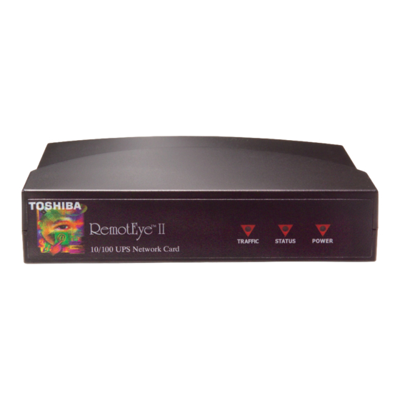
Page 135: Remoteye Ii/External Hardware Specification
Status (Amber) LAN 10 Link/Activity (Amber) LAN 100 Link/Activity (Green) Jumpers Clear Password Reset Button Reset System UPS Protocol Toshiba UPS Communication Protocol Network Protocol SNMP over UDP/IP HTTP over TCP/IP ARP,RARP,TFTP and ICMP Supported MIB MIB_II TOSHIBA V2.50 MIB... -
Page 136: Led Indicator
Figure 32: RemotEye II/External Front View 12VDC Reset NETWORK Figure 33: RemotEye II/External Back View DIP-Switch Description Function Mode Manufacture Diagnostic Mode Reserved Firmware Upgrade Operating Mode LED Indicator Status Traffic Function Mode Solid OFF Solid ON Normal operation Solid OFF Flashing Ethernet traffic Flashing... -
Page 137: Cables Definition
Cables Definition The UPS Cable of RemotEye II/External Item Description RJ45 DB9(Male) Ready to Send Transmitted Data Signal Ground Chassis Ground Case GND Received Data Clear to Send Note: The pin 2 and pin 7 of RJ45 connector are connected internally. The PC Cable of RemotEye II/External &...